📝 12 Apr 2022
Pine64 PineDio Stack BL604 RISC-V Board
PineDio Stack BL604 is Pine64’s newest microcontroller board, based on Bouffalo Lab’s BL604 RISC-V + WiFi + Bluetooth LE SoC.
(Available any day now!)
PineDio Stack is packed chock-full of features…
ST7789 Colour LCD Display
(240 x 240 pixels)
CST816S Touch Panel
(Connected on I2C)
Semtech SX1262 LoRa Transceiver
(Works with LoRaWAN wireless networks)
AT6558 GPS / GNSS Receiver
SGM40561 Power Management Unit
Heart Rate Sensor, Accelerometer, Compass, Vibrator
SPI Flash, JTAG Debugging Port, Push Button
2.4 GHz WiFi, Bluetooth LE
(Thanks to BL604)
Which makes it an awesome gadget for IoT Education!
(It looks like a “Chonky PineTime”… It has the same display and touch panel as PineTime)
Today we shall build, flash and run the open-source, community-supported Apache NuttX RTOS (Real-Time Operating System) on PineDio Stack…
And get started on creating our own IoT Apps!
Pine64 PineDio Stack BL604 RISC-V Board
Apache NuttX is a popular Real-Time Operating System (RTOS) for microcontrollers (8-bit to 64-bit). It runs on all kinds of hardware: Arm, ESP32, RISC-V, … Even flying drones!
NuttX feels like a lighter version of Linux because it uses familiar functions to access the microcontroller hardware: open(), read(), write(), ioctl(), …
(NuttX is POSIX Compliant)
We’ve done many fun experiments with NuttX on BL602 and BL604: ST7789 Display, BME280 Sensor, IKEA Air Quality Sensor, Internal Temperature Sensor, LoRa, LoRaWAN, Rust, BASIC, CBOR, … And now PineDio Stack.
The source code for NuttX on PineDio Stack is here…
Let’s go hands-on with NuttX!
NuttX builds fine on Linux (x64), macOS and Windows Subsystem for Linux (WSL).
Here are the steps to build NuttX for PineDio Stack…
Install the build prerequisites…
Enter these commands to download, configure and build NuttX…
## Download NuttX for PineDio Stack
mkdir nuttx
cd nuttx
git clone --recursive --branch pinedio https://github.com/lupyuen/nuttx nuttx
git clone --recursive --branch pinedio https://github.com/lupyuen/nuttx-apps apps
## Configure NuttX for PineDio Stack
cd nuttx
./tools/configure.sh bl602evb:pinedio
## Build NuttX for PineDio Stack
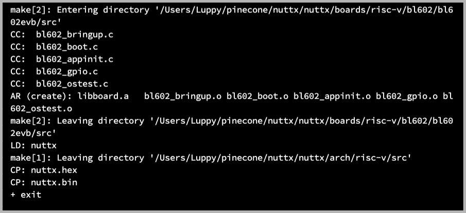
makeWe should see…
LD: nuttx
CP: nuttx.hex
CP: nuttx.bin
We have successfully built the NuttX Firmware for PineDio Stack!
For WSL: Copy the NuttX Firmware to the c:\blflash directory in the Windows File System…
##  /mnt/c/blflash refers to c:\blflash in Windows
mkdir /mnt/c/blflash
cp nuttx.bin /mnt/c/blflash
We’ll flash PineDio Stack with Windows Command Prompt (CMD) because we need the COM port.
What’s “bl602evb:pinedio”?
That’s the NuttX Build Configuration for PineDio Stack. It selects the Build Options, NuttX Drivers and NuttX Apps that will run on PineDio Stack.
Let’s get ready to flash the NuttX Firmware to PineDio Stack!
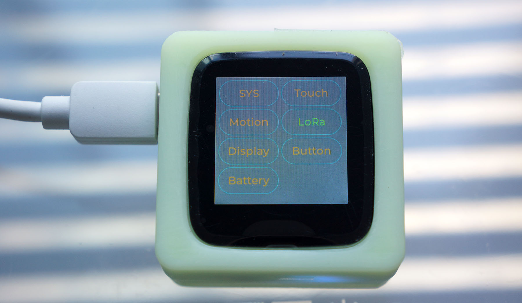
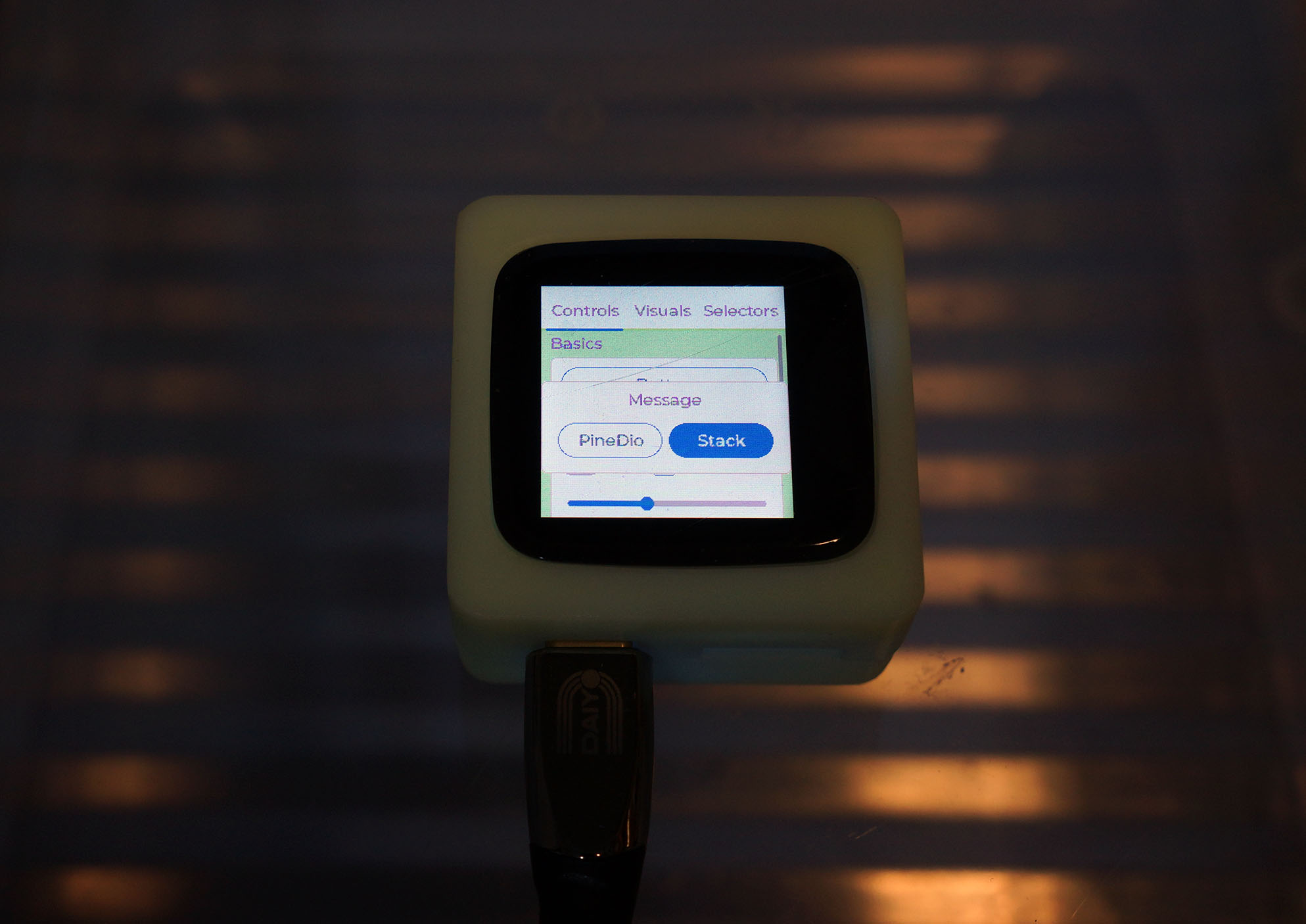
Connect PineDio Stack to our computer’s USB Port.
The Self Test screen appears. (Pic above)
Tap each button to verify that PineDio Stack is OK.
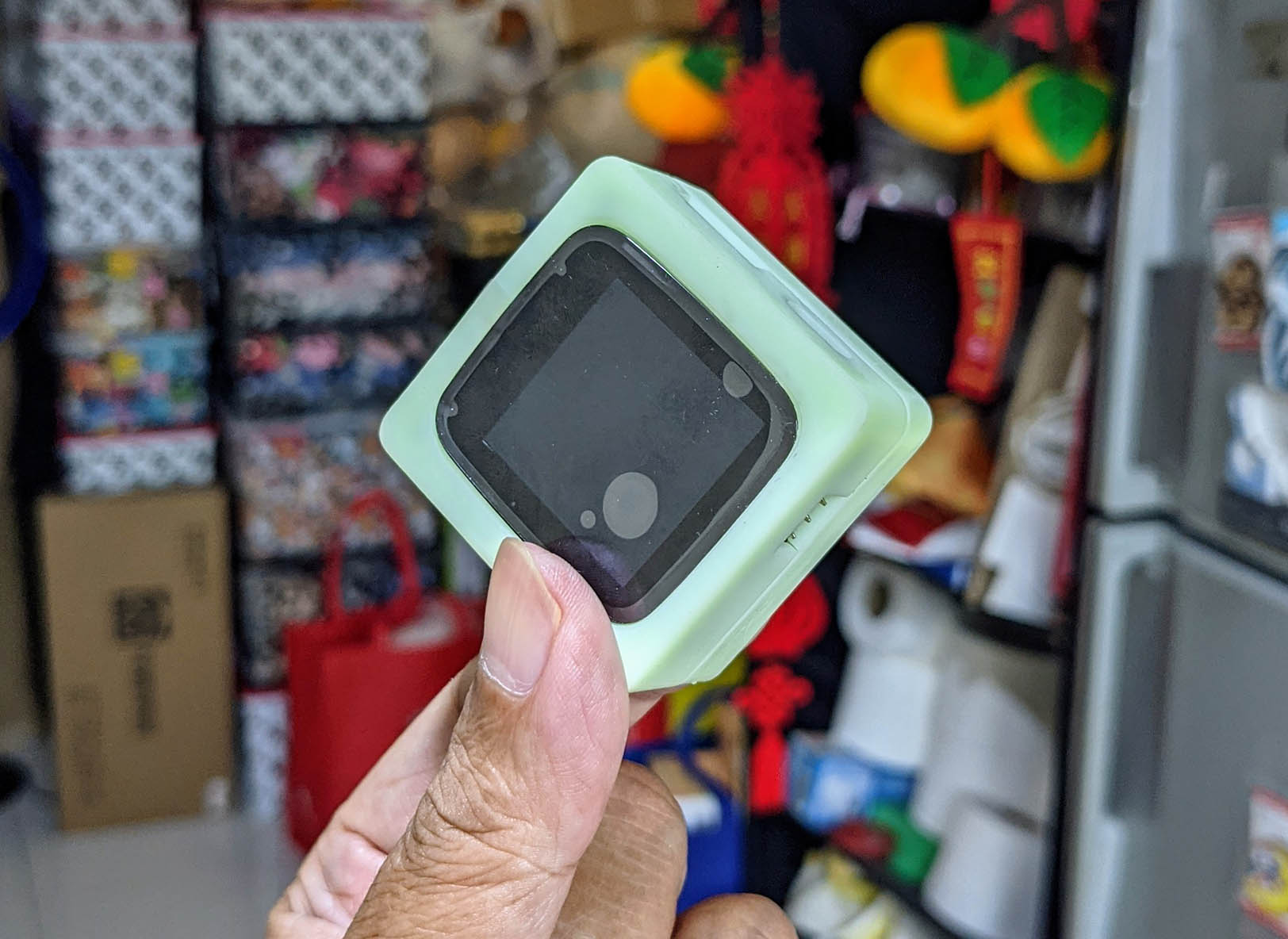
Disconnect PineDio Stack from the USB Port.
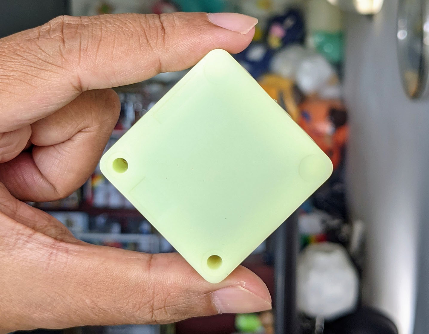
Carefully open the Back Cover of PineDio Stack. (Pic above)
(Don’t remove the display!)
We’ll see the PineDio Stack Baseboard…
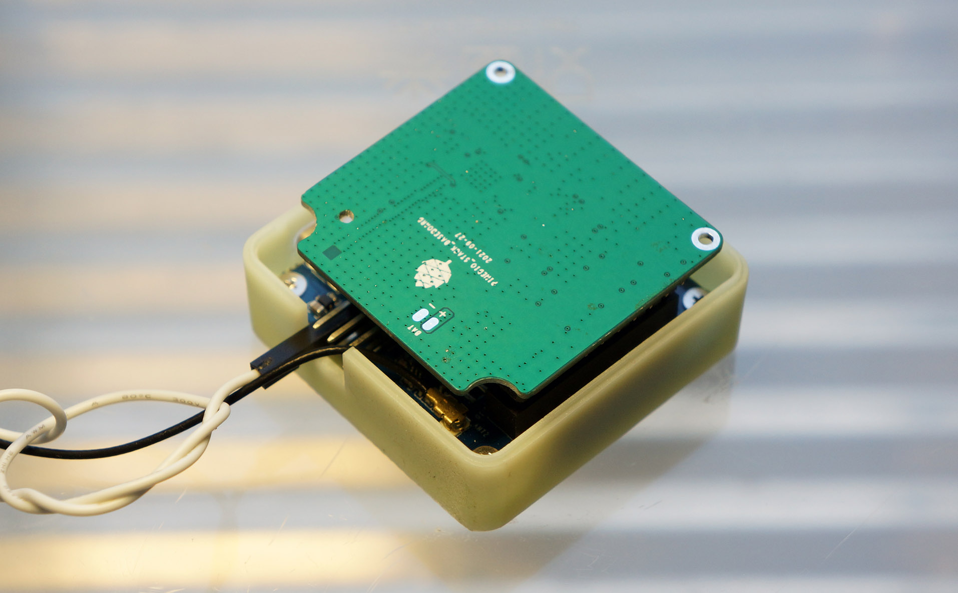
Carefully remove the PineDio Stack Baseboard.
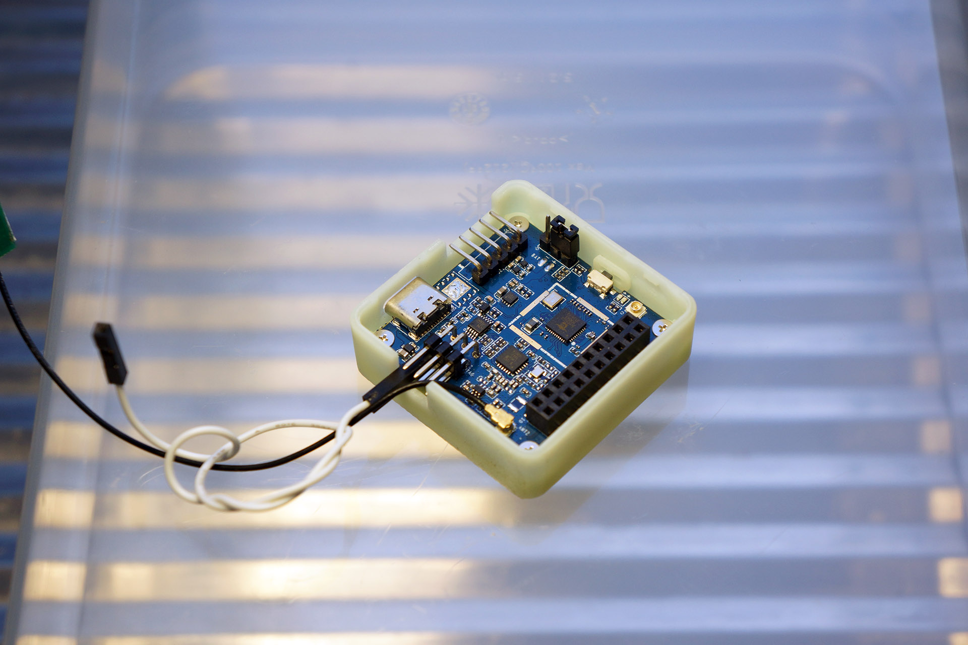
We’ll see the Main Board…
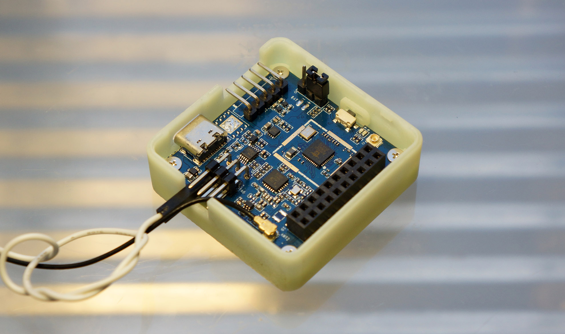
What’s on the Main Board?
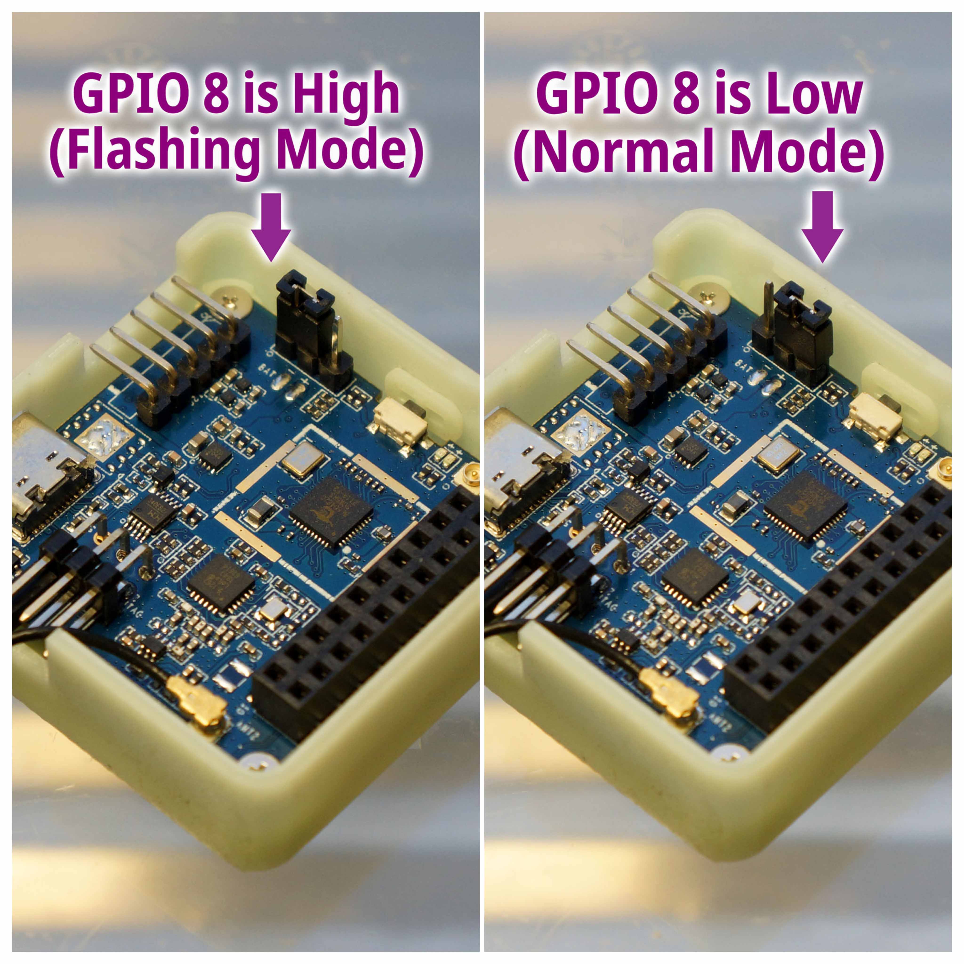
GPIO 8 Jumper (top right): Set PineDio Stack to Flashing Mode or Normal Mode
Improvised Reset Button (lower left): We connect a Jumper Cable (to the I2C Port) to restart PineDio Stack during flashing and testing
LoRa Antenna (bottom): Connect an antenna here if we’re testing LoRa
WiFi / Bluetooth LE Antenna (right): Connect an antenna here if we’re testing WiFi or Bluetooth LE
JTAG Port (top left): For debugging (but not flashing)
GPIO Port (lower right): Connects the baseboard
Push Button (just below the jumper): Works like a watch button
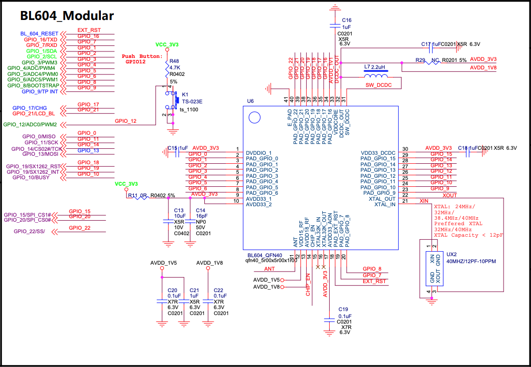
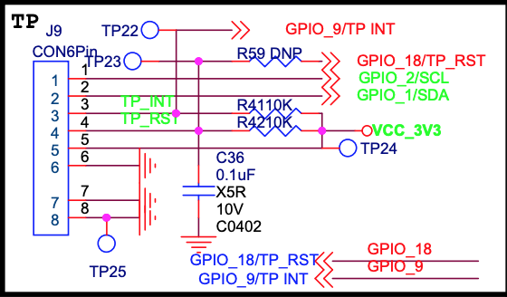
Check out the PineDio Stack Schematics…
We’re ready to flash PineDio Stack!
Let’s flash the NuttX Firmware to PineDio Stack. Follow these steps to install blflash…
Set PineDio Stack to Flashing Mode and restart the board…
Set the GPIO 8 Jumper to High (Like this)
Disconnect the USB cable and reconnect
Or use the Improvised Reset Button (Here’s how)
Enter these commands to flash nuttx.bin to PineDio Stack…
(For WSL: Do this in Windows Command Prompt CMD instead of WSL. blflash needs to access the COM port)
## For Linux: Change "/dev/ttyUSB0" to the PineDio Stack Serial Port
blflash flash nuttx.bin \
--port /dev/ttyUSB0
## For macOS: Change "/dev/tty.usbserial-1410" to the PineDio Stack Serial Port
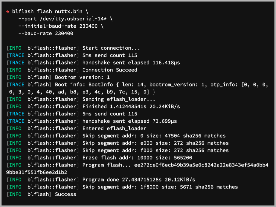
blflash flash nuttx.bin \
--port /dev/tty.usbserial-1410 \
--initial-baud-rate 230400 \
--baud-rate 230400
## For Windows: Change "COM5" to the PineDio Serial Port
blflash flash c:\blflash\nuttx.bin --port COM5We should see…
Sending eflash_loader...
Erase flash addr: 10000 size: 565200
Program flash...
Program done 27.434715128s 20.12KiB/s
SuccessNuttX has been flashed to PineDio Stack!
Will PineDio Stack get bricked if we flash bad firmware?
After using BL602 and BL604 for 1.5 years, I’ve never bricked a single BL602 or BL604 board.
So go ahead and create your own PineDio Stack firmware, it’s all OK!
(Flashing WiFi apps? See this)
Like Linux, NuttX provides a Command-Line Interface for controlling our gadget. This is how we access the NuttX Shell…
Set PineDio Stack to Normal Mode (Non-Flashing) and restart the board…
Set the GPIO 8 Jumper to Low (Like this)
Disconnect the USB cable and reconnect
Or use the Improvised Reset Button (Here’s how)
After restarting, connect a Serial Terminal to PineDio Stack at 2 Mbps…
For Linux: Use screen
screen /dev/ttyUSB0 2000000For macOS: Use CoolTerm (See this)
For Windows: Use putty (See this)
Alternatively: Use the Web Serial Terminal (See this)
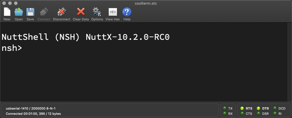
Press Enter to reveal the NuttX Shell…
NuttShell (NSH) NuttX-10.2.0-RC0
nsh>
Congratulations NuttX is now running on PineDio Stack!
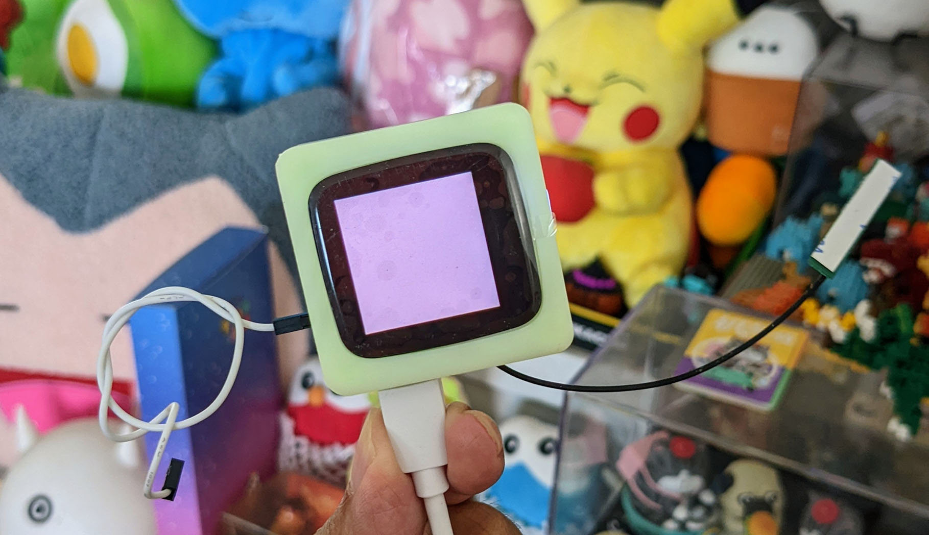
NuttX boots with a Pink Screen. (Pic above)
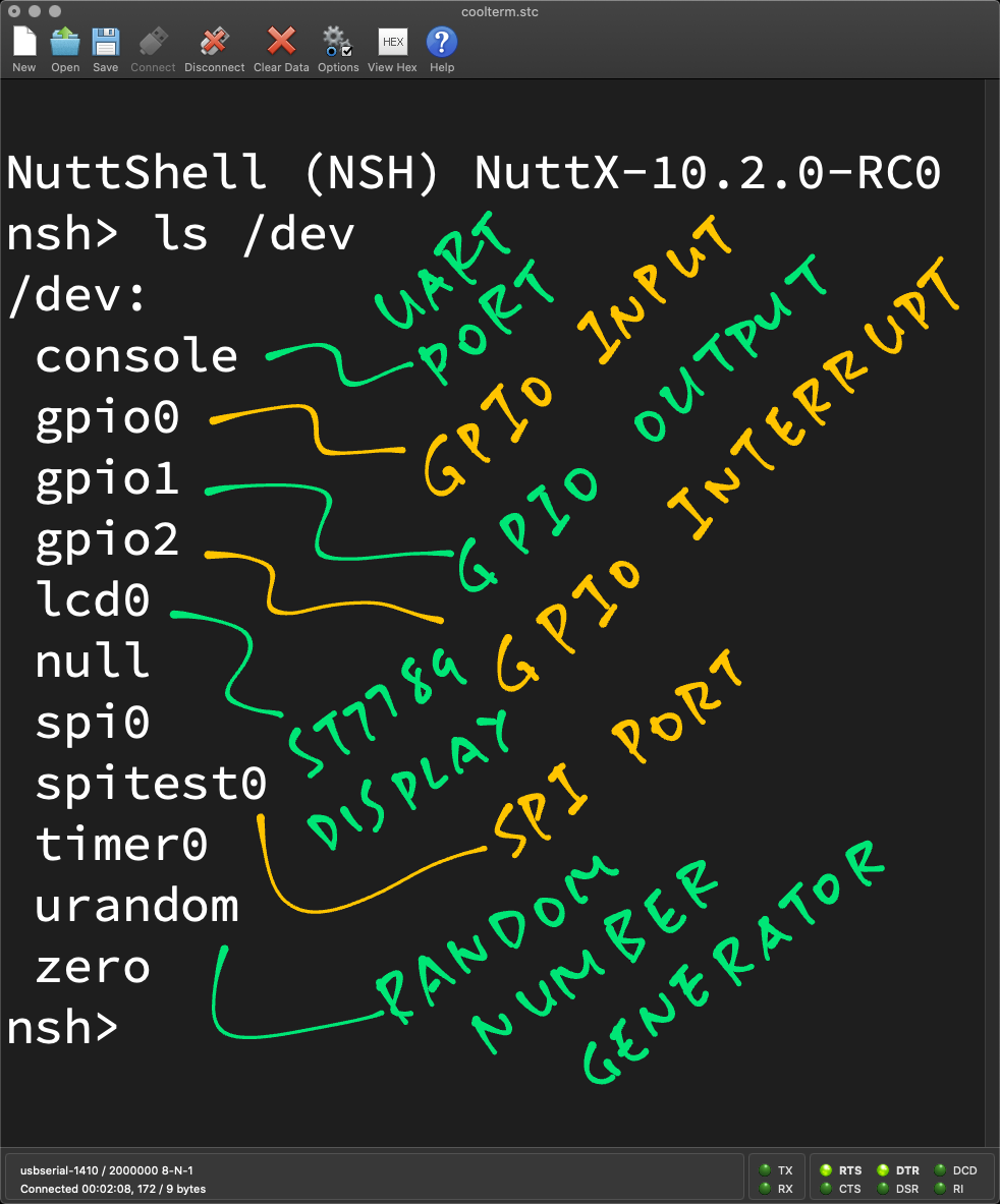
In the NuttX Shell, enter this command…
ls /devWe see a list of Device Drivers that were loaded by NuttX. (Pic below)
Now that NuttX is up, let’s run some NuttX Apps!
In the NuttX Shell, enter this command…
help(“?” works too)
We see a list of NuttX Apps that have been installed…
Builtin Apps:
bas lorawan_test spi_test2
bl602_adc_test lvgltest sx1262_test
getprime nsh timer
gpio sensortest tinycbor_test
hello spi
i2c spi_test
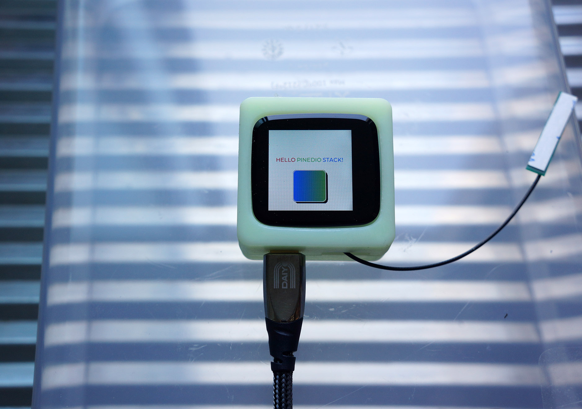
ikea_air_quality_sensorEnter this to run the LVGL Test App…
lvgltestFollow the prompts to tap the screen and calibrate the Touch Panel.
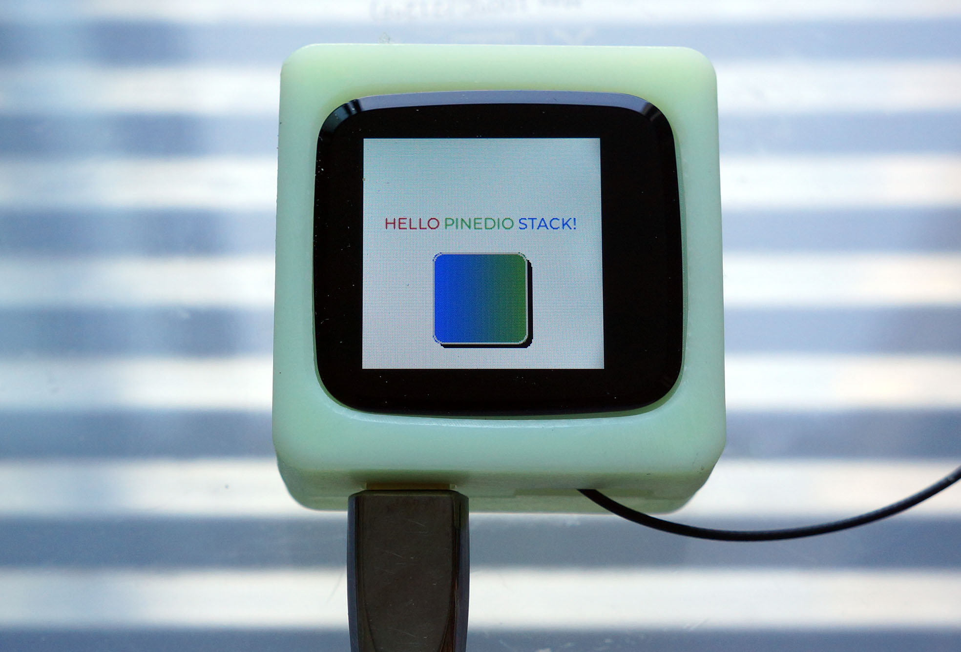
After calibrating, this appears on the screen: “Hello PineDio Stack!” with a funky blue-green box…
Can we render our own text and graphics?
Sure can! Below is the code that renders the screen, by calling the LVGL Graphics Library…
//  Create the LVGL Widgets that will be rendered on the display
static void create_widgets(void) {
  //  Get the Active Screen
  lv_obj_t *screen = lv_scr_act();

  //  Create a Label Widget
  lv_obj_t *label = lv_label_create(screen, NULL);

  //  Wrap long lines in the label text
  lv_label_set_long_mode(label, LV_LABEL_LONG_BREAK);

  //  Interpret color codes in the label text
  lv_label_set_recolor(label, true);

  //  Center align the label text
  lv_label_set_align(label, LV_LABEL_ALIGN_CENTER);

  //  Set the label text and colors
  lv_label_set_text(
    label,
    "#ff0000 HELLO# "    //  Red Text
    "#00ff00 PINEDIO# "  //  Green Text
    "#0000ff STACK!# "   //  Blue Text
  );

  //  Set the label width
  lv_obj_set_width(label, 200);

  //  Align the label to the center of the screen, shift 30 pixels up
  lv_obj_align(label, NULL, LV_ALIGN_CENTER, 0, -30);

// Omitted: Render a rounded rectangle with LVGL CanvasTo render our own text and graphics, edit this source file and change the code above…
apps/examples/lvgltest/lvgltest.cThen rebuild (“make”) and reflash (“blflash”) NuttX to PineDio Stack.
So touchscreen apps are supported on PineDio Stack?
Yep! See this for the details…
What other NuttX Apps can we try?
hello: Prints “Hello World”
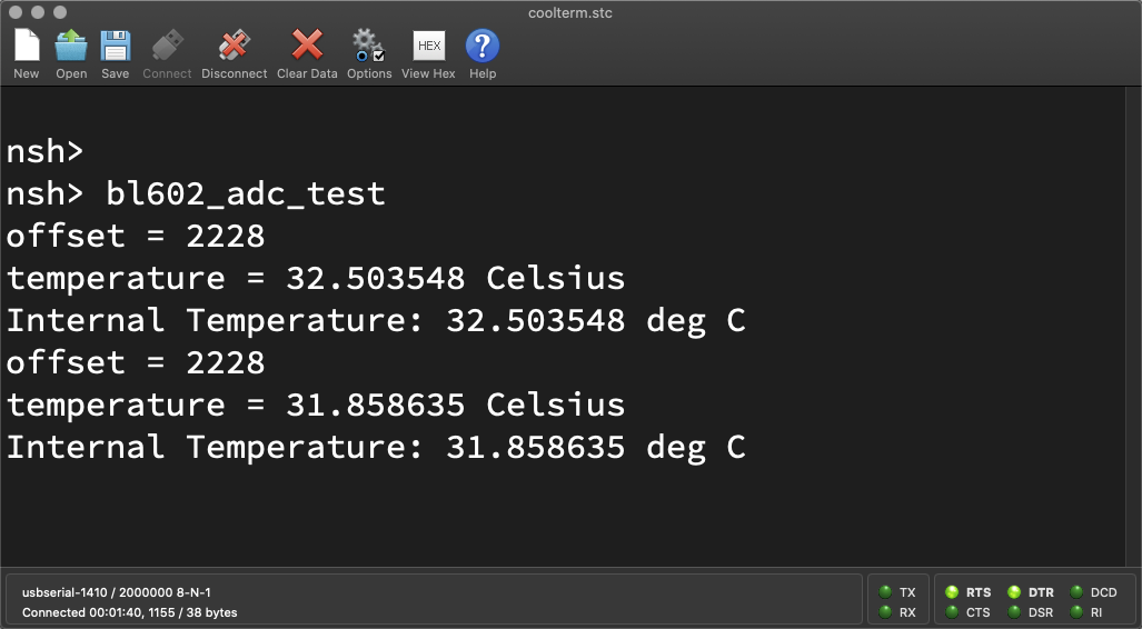
bl602_adc_test: Shows the Internal Temperature of BL604
bas: BASIC Interpreter (Ctrl-D to quit)
What about LoRa on PineDio Stack?
We have NuttX Apps for testing LoRa and LoRaWAN wireless networking.
See the Appendix for details…
If we wish to create our own NuttX Apps?
Refer to the docs for the steps to create our own NuttX Apps, Libraries and Drivers…
Here are some Troubleshooting Tips…
Also check out the NuttX Articles on all kinds of topics…
Shared SPI Bus on PineDio Stack
So PineDio Stack runs all hunky dory on NuttX?
Not completely. PineDio Stack’s Shared SPI Bus works great on NuttX after we modded the SPI Driver…
The ST7789 Display runs well with NuttX’s ST7789 Driver and LVGL Library right out of the box, with one tweak…
And the SX1262 LoRa Transceiver works fine with Semtech’s Reference Drivers for LoRa and LoRaWAN…
But there’s plenty more porting work to be done!
If you’re keen to help, please lemme know! 🙏
I hope this article has provided everything you need to get started on creating your own IoT App.
Lemme know what you’re building with PineDio Stack!
Many Thanks to my GitHub Sponsors for supporting my work! This article wouldn’t have been possible without your support.
Got a question, comment or suggestion? Create an Issue or submit a Pull Request here…
lupyuen.github.io/src/pinedio2.md
This article is the expanded version of this Twitter Thread
Got a question for Bouffalo Lab? Check out their Developer Forum…
Also check out the Nutcracker Channel on Matrix, Telegram, Discord or IRC…
Besides NuttX, there are two other ways to code firmware for PineDio Stack…
BL IoT SDL: Supports WiFi and is based on FreeRTOS
BL MCU SDK: Doesn’t support WiFi, also based on FreeRTOS)
The PineDio Stack Self-Test Firmware was created by JF with BL MCU SDK…
LVGL Canvas consumes a lot of RAM! Disable it if we don’t really need it, we’ll save 7 KB of RAM…
Configure NuttX with “make menuconfig”
Select “Application Configuration → Graphics Support → Light and Versatile Graphic Library (LVGL) → Object Type Usage Settings”
Uncheck “Canvas Usage”
Save and exit menuconfig, then rebuild NuttX (make)
The Baseboard Schematic includes a Secure Chip ATECC608A. We talk about it here…
What’s it like to test the First (Buggy) Prototype of PineDio Stack? Find out here…
Acording to the PineDio Stack Schematics…
These are the BL604 GPIOs used by PineDio Stack…
| GPIO | Port | Function | Other Functions |
|---|---|---|---|
0 | SPI | MISO | |
1 | Int I2C | SDA | |
2 | Int I2C | SCL | |
3 | Ext I2C | SDA | ST7789 Reset, Compass Interrupt |
4 | Ext I2C | SCL | GPS Reset |
5 | Ext I2C | Accelerometer Interrupt, GPS On/Off | |
6 | Power Mgmt | VBAT | |
7 | UART | RX | GPS RX |
8 | Flashing Mode | ||
9 | Touch Panel | Interrupt | |
10 | SX1262 | Busy | |
11 | SPI | SCK | JTAG TDO |
12 | Vibrator | JTAG TMS, Push Button | |
13 | SPI | MOSI | JTAG TDI |
14 | SPI Flash | CS | JTAG TCK |
15 | SX1262 | CS | |
16 | UART | TX | GPS TX |
17 | Power Mgmt | CHG | Red LED |
18 | SX1262 | Reset | Touch Panel Reset |
19 | SX1262 | Interrupt | |
20 | ST7789 | CS | |
21 | ST7789 | Backlight | |
22 | Heart Rate | Interrupt |
SPI Bus “/dev/spi0” is shared by ST7789 Display, SX1262 LoRa Transceiver and SPI Flash
Internal I2C Bus “/dev/i2c0” is shared by Accelerometer, Touch Panel, Heart Rate Sensor and Compass
UART Port “/dev/console” is shared by Serial Console and GPS
(This will be a problem, in spite of their different baud rates)
GPIO Ports “/dev/gpio0” to “/dev/gpio22” are mapped to GPIO Pins 0 to 22
(Except the pins reserved for the UART, I2C and SPI Ports)
The NuttX Pin Definitions for PineDio Stack are at…
boards/risc-v/bl602/bl602evb/include/board.h
Earlier we ran this command to configure the NuttX Build for PineDio Stack BL604…
./tools/configure.sh bl602evb:pinedioThe above command bundles the following NuttX Drivers, Libraries and Apps into NuttX for PineDio Stack…
The NuttX Configuration File for PineDio Stack is at…
boards/risc-v/bl602/bl602evb/configs/pinedio/defconfig
This section discusses the upcoming features that we’ll implement with NuttX on PineDio Stack BL604.
If you’re keen to help, please lemme know! 🙏
UPDATE: We have implemented the GPIO Expander, so we’re no longer stuck with 3 GPIOs
BL604 has 23 GPIOs. Can we use all of them in NuttX Apps?
Some of the GPIOs will be used for SPI, I2C and UART. But we still have a lot of remaining GPIOs to manage!
NuttX allows apps to access to a total of 3 GPIOs on BL604…
/dev/gpio0: GPIO Input
(Configured as GPIO 10)
/dev/gpio1: GPIO Output
(Configured as GPIO 15)
/dev/gpio2: GPIO Interrupt
(Configured as GPIO 19)
(All 3 GPIOs are already used by the SX1262 Library. See this)
Adding the remaining GPIOs to the BL604 GPIO Driver at compile-time will be cumbersome. (See this)
We need a flexible way to manage many GPIOs at runtime, as we build new apps and drivers for PineDio Stack.
Is there a way to aggregate the GPIOs without defining them at compile-time?
NuttX supports GPIO Expanders that will aggregate multiple GPIOs…
We shall implement a GPIO Expander for BL604 that will handle multiple GPIOs by calling bl602_configgpio, bl602_gpioread and bl602_gpiowrite.
The GPIO Expander will expose GPIOs 0 to 22 as “/dev/gpio0” to “/dev/gpio22”.
Won’t this break the existing GPIOs that are in use?
We’ll skip “/dev/gpio0” to “/dev/gpio2” because they are already used by the SX1262 Driver. (See this)
(On PineDio Stack: GPIO 0 is MISO, GPIO 1 is SDA, GPIO 2 is SCL. So we shouldn’t touch GPIOs 0, 1 and 2 anyway. See this)
Wow this sounds messy?
But it might be the most productive way (for now) to handle so many GPIOs while multiple devs are building apps and drivers for PineDio Stack.
Perhaps the GPIO Expander can enforce checks at runtime to be sure that NuttX Apps don’t tamper with the GPIOs used by SPI, I2C and UART.
(And eventually the SX1262 Library will simply access “/dev/gpio10”, “/dev/gpio15” and “/dev/gpio19”)
More details on the GPIO Expander…
The GPIO Expander shall also manage GPIO Interrupts for the Touch Panel, SX1262 Transceiver, Push Button, Compass, Accelerometer, Heart Rate Sensor, …
There’s a discussion about GPIOs on BL604…
NuttX Apps vs NuttX Drivers… Do they handle GPIOs differently?
NuttX Drivers run in Kernel Mode and can access the GPIO Hardware directly by calling bl602_configgpio, bl602_gpioread and bl602_gpiowrite.
(So no problems handling many GPIOs)
NuttX Apps run in User Mode and can only access GPIOs through “/dev/gpioN”
(Which becomes a problem when we have many GPIOs)
NuttX Apps are easier to code than NuttX Drivers.
(That’s our experience with LoRa)
Thus we expect most PineDio Stack devs to create NuttX Apps first before moving the code into NuttX Drivers.
That’s why we need to handle GPIOs the messy (but productive) way for now.
Robert Lipe has an excellent article on PineDio Stack’s Push Button…
To support the Push Button (GPIO 12) on PineDio Stack, we shall implement these Board Button Functions for PineDio Stack…
(Here’s the implementation for ESP32)
They will be called by the Button Lower Half Driver in NuttX…
Which is wrapped inside the Button Upper Half Driver and exposed to apps as “/dev/buttons”…
(Here’s how we access “/dev/buttons” in NuttX Apps)
Note that the Push Button shares GPIO 12 with the Vibrator.
(Which is missing from the current PineDio Stack)
JF has created a CST816S I2C Touch Panel Driver for PineDio Stack… (Thanks JF!)
We have ported this driver to NuttX and exposed it to apps as a NuttX Touchscreen Device “/dev/input0”…
(Here’s how we access “/dev/input0” in our LVGL Test App)
More about the NuttX Touch Panel Driver for PineDio Stack…
(PineDio Stack uses the same Touch Panel as PineTime)
(More about NuttX Touchscreen Drivers)
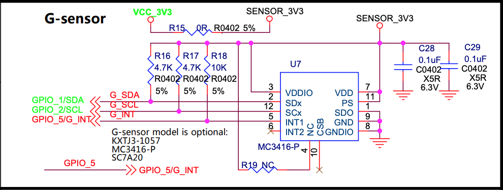
To create the I2C Accelerometer Sensor Driver “/dev/accel0” for PineDio Stack, we could port JF’s simple driver…
Or the Reference Driver for MC3416…
The NuttX Driver for WTGAHRS2 Accelerometer might be a good guide for porting the driver.
We have an article that explains the innards of NuttX Sensor Drivers…
NuttX’s I2C Tool might be helpful for troubleshooting I2C Drivers.
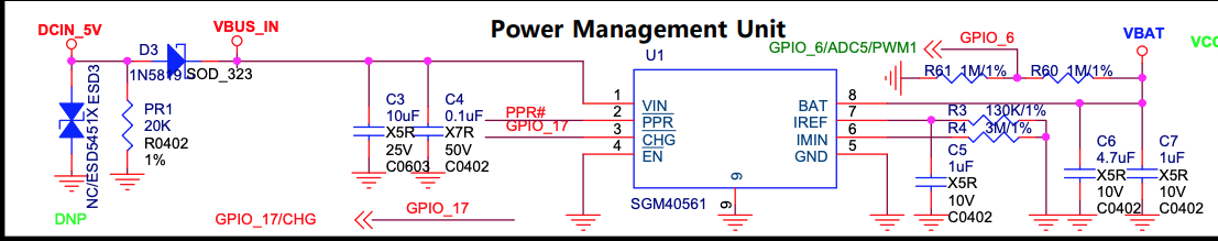
Check out JF’s driver for SGM40561 Power Management Unit…
(This is the same Power Management Unit used in PineTime)
To port this to NuttX, we’ll call the BL604 ADC Library…
(Because BL604 ADC is not supported yet on NuttX)
Refer to the Power Management Drivers for NuttX…
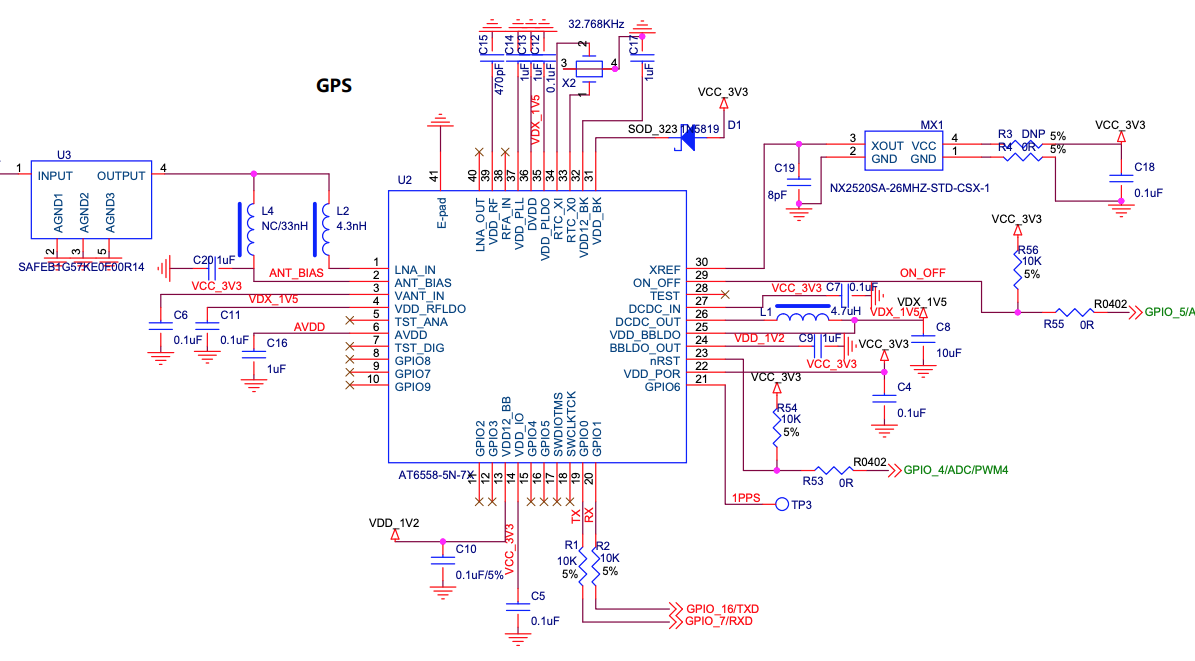
NuttX has a GPS Demo App…
And a GPS Parser Library…
These might be helpful for creating the GPS Driver (UART) for PineDio Stack.
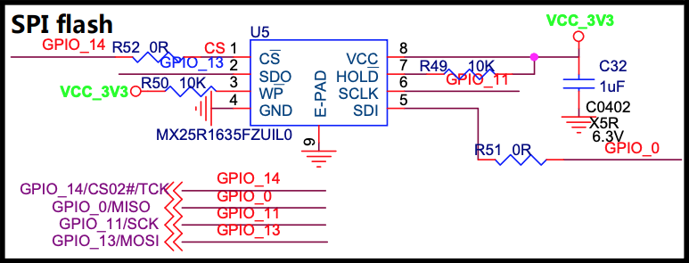
The PineDio Stack Schematics refer to 2 kinds of SPI Flash… (Why?)
MX25R1635FZUIL0 (Main Board)
W25Q128FV / W25Q256FV (Baseboard)
Both kinds of SPI Flash seem to be supported by NuttX…
We need to test the drivers.
NuttX’s SPI Tool might be helpful for troubleshooting SPI Drivers.
ST7789 Display receives plenty of data on the SPI Bus (for screen updates). Will there be contention with other SPI Devices? (Like SX1262 Transceiver)
Most definitely. That’s why we need to implement SPI Direct Memory Access (DMA) so that PineDio Stack can do other tasks while painting the ST7789 Display.
(Right now the SPI Driver polls the SPI Port when transferring SPI data)
We’ll port to NuttX this implementation of SPI DMA from BL MCU SDK…
More about SPI DMA on BL602 / BL604…
UPDATE: SPI DMA is now supported on BL602 / BL604 NuttX…
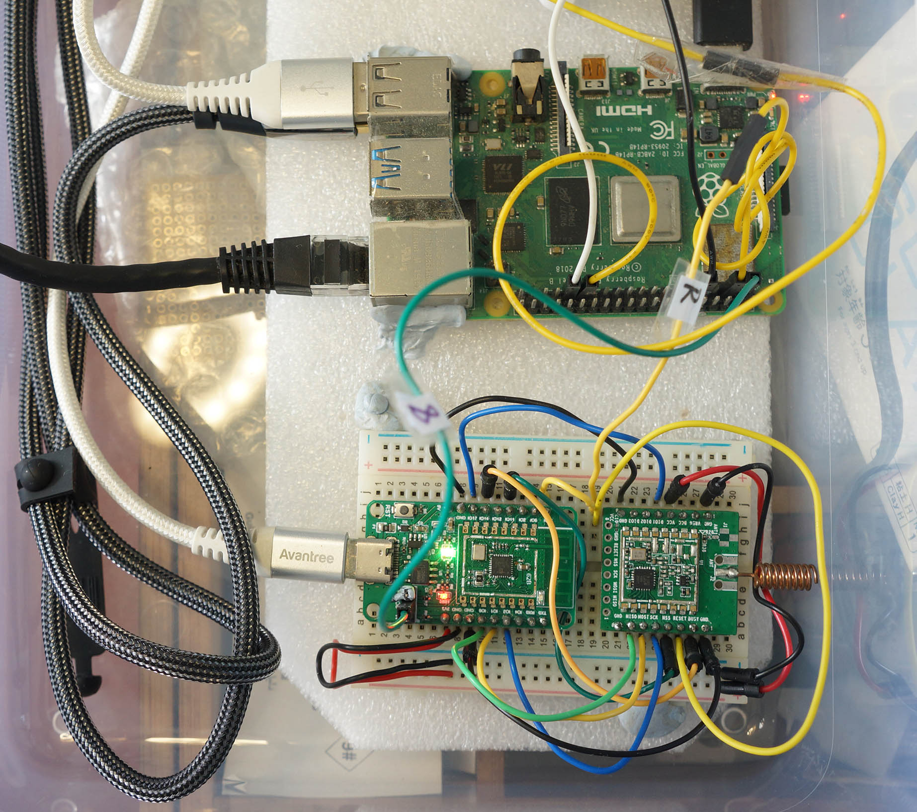
PineCone BL602 RISC-V Board (bottom) connected to Single-Board Computer (top) for Auto Flash and Test
UPDATE: Automated Testing for PineDio Stack is explained in this article…
When we have multiple devs creating NuttX Apps and Drivers for PineDio Stack, it might be good to run some Automated Testing (to be sure that nothing’s broken).
Today we run a Daily Automated Test on the NuttX Mainline Branch for PineCone BL602…
Now we need to connect an SBC to PineDio Stack and auto-run these tests…
SPI Test App (spi_test2): Verify that the SPI Driver can talk to SX1262
LoRaWAN Test App (lorawan_test): Verify that SX1262 can join a LoRaWAN Network (ChirpStack) and transmit Data Packets
LVGL Test App (lvgltest): Verify that ST7789 can render an LVGL Screen (over SPI) and read the CST816S Touch Panel (over I2C)
GPIO Command (gpio): Verify that the BL604 GPIO Expander correctly triggers an interrupt when the Push Button is pressed…
nsh> gpio -t 8 -w 1 /dev/gpio12
Driver: /dev/gpio12
  Interrupt pin: Value=1
Verify: Value=1Right now we run these tests manually on PineDio Stack when we update the pinedio branch.
We record the Manual Test Logs in the Pull Requests…
So we’ll run Automated Tests on PineCone BL602 AND PineDio Stack BL604?
Yep we shall test and maintain two Stable Branches of NuttX for public consumption…
master branch for PineCone BL602
pinedio branch for PineDio Stack BL604
(Same for NuttX Apps)
Are the branches any different?
The code should be identical, though…
PineCone BL602 won’t use the Shared SPI Bus that we have created for PineDio Stack BL604
PineCone BL602 won’t use the GPIO Expander either
We control the options through the NuttX Build Configuration…
## Configure build for PineDio Stack BL604
./tools/configure.sh bl602evb:pinedio

## Configure build for PineCone BL602
./tools/configure.sh bl602evb:pinecone
(See the PineDio Stack config)
This check for PineDio Stack should probably be improved: board.h
/* Identify as PineDio Stack if both ST7789 and CST816S are present */
#if defined(CONFIG_LCD_ST7789) && defined(CONFIG_INPUT_CST816S)
#define PINEDIO_STACK_BL604
#endif /* CONFIG_LCD_ST7789 && CONFIG_INPUT_CST816S */(PINEDIO_STACK_BL604 enables the SPI Device Table in the SPI Driver)
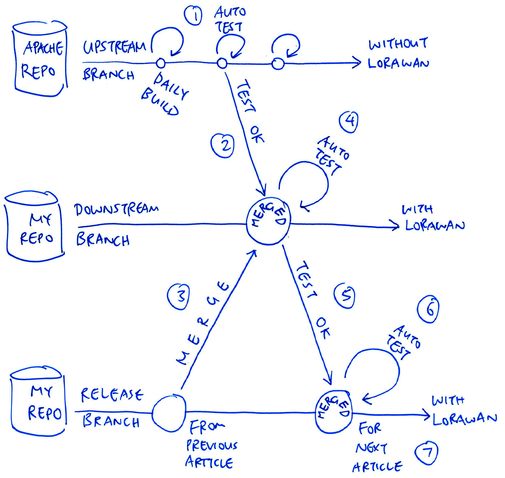
What about upstream updates from NuttX Mainline Branch?
Upstream updates from NuttX Mainline will first be merged and auto-tested in the downstream branch
(Every 2 weeks, depends on my writing mood)
Then merged and auto-tested in the master (release) branch
(For PineCone BL602)
Which gets merged and manually tested in the pinedio branch
(For PineDio Stack BL604)
Updates in the pinedio branch are merged back to the master and the downstream branches and auto-tested on PineCone BL602
Thus ultimately the pinedio, master and downstream branches will all have the exact same code, tested OK on PineCone BL602 and PineDio Stack BL604
(And lagging behind NuttX Mainline by 2 weeks)
This is an extension of our original grand plan…
But how will we auto-test the Touch Panel on PineDio Stack?
With a Robot Finger?
Or let our SBC actuate a Motor that’s wrapped in an Anti-Static Bag?
I’m open to ideas, please lemme know! 🙏
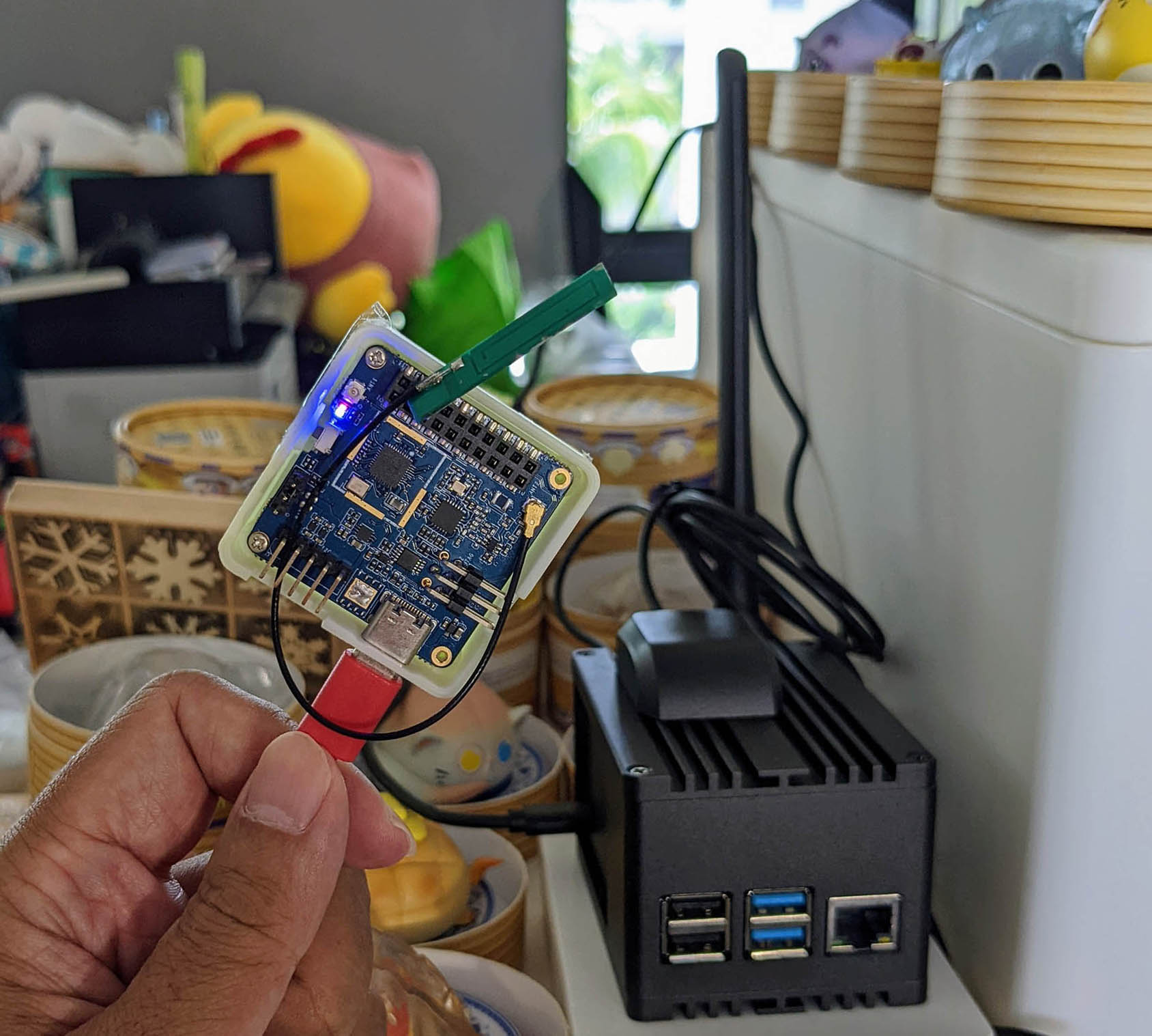
PineDio Stack BL604 RISC-V Board (left) talking LoRaWAN to RAKwireless WisGate LoRaWAN Gateway (right)
PineDio Stack BL604 includes a Semtech SX1262 LoRa Transceiver for wireless networking.
This section explains how we may test LoRa and LoRaWAN Wireless Networking on PineDio Stack.
Why LoRa?
LoRa is a Low-Power, Long-Range, Low-Bandwidth wireless network.
LoRa is perfect for IoT Sensor Devices that run on Battery Power. (Or Solar Power)
Will LoRa support all kinds of messages?
Not quite. LoRa only supports Short Messages of up to 242 Bytes.
And because LoRa is a Low Power (best effort) network, messages may get dropped. Which is probably OK for sensor devices that send data periodically.
(But not for texting your friends)
Is LoRa secure?
LoRa messages are delivered securely when we join a LoRaWAN Network.
Today we shall test both LoRa and LoRaWAN on PineDio Stack…
Transmit and receive raw LoRa Messages
Join a LoRaWAN Network and transmit a LoRaWAN Message to a LoRaWAN Gateway (like ChirpStack or The Things Network)
The LoRa Library for Semtech SX1262 is explained in this article…
To test LoRa on PineDio Stack, edit sx1262_test_main.c at…
apps/examples/sx1262_test/sx1262_test_main.cAnd update the LoRa Parameters…
/// TODO: We are using LoRa Frequency 923 MHz
/// for Singapore. Change this for your region.
#define USE_BAND_923
...

/// LoRa Parameters
#define LORAPING_TX_OUTPUT_POWER            14        /* dBm */

#define LORAPING_BANDWIDTH                  0         /* [0: 125 kHz, */
                                                      /*  1: 250 kHz, */
                                                      /*  2: 500 kHz, */
                                                      /*  3: Reserved] */
#define LORAPING_SPREADING_FACTOR           7         /* [SF7..SF12] */
#define LORAPING_CODINGRATE                 1         /* [1: 4/5, */
                                                      /*  2: 4/6, */
                                                      /*  3: 4/7, */
                                                      /*  4: 4/8] */
#define LORAPING_PREAMBLE_LENGTH            8         /* Same for Tx and Rx */
#define LORAPING_SYMBOL_TIMEOUT             5         /* Symbols */
#define LORAPING_FIX_LENGTH_PAYLOAD_ON      false
#define LORAPING_IQ_INVERSION_ON            false

#define LORAPING_TX_TIMEOUT_MS              3000    /* ms */
#define LORAPING_RX_TIMEOUT_MS              10000    /* ms */
#define LORAPING_BUFFER_SIZE 64 /* LoRa message size */The parameters are explained here…
Then uncomment SEND_MESSAGE or RECEIVE_MESSAGE to send or receive a LoRa Message…
int main(int argc, FAR char *argv[]) {
...
//  Uncomment to send a LoRa message
#define SEND_MESSAGE
...
//  Uncomment to receive a LoRa message
#define RECEIVE_MESSAGERebuild (“make”) and reflash (“blflash”) NuttX to PineDio Stack.
In the NuttX Shell, enter this to run the LoRa Test App…
sx1262_testIf we’re sending a LoRa Message on PineDio Stack, we’ll see the message received by the LoRa Receiver Device…
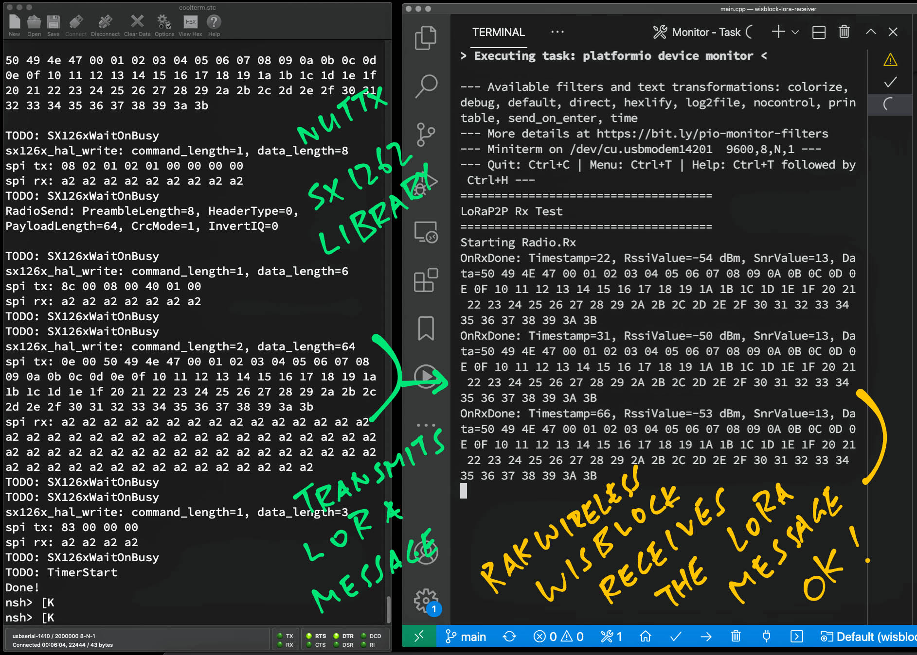
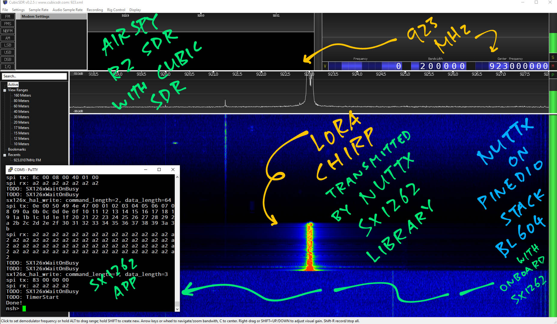
To troubleshoot LoRa, we could use a Spectrum Analyser (Software-Defined Radio)…
The LoRaWAN Library is explained in this article…
To test LoRaWAN on PineDio Stack, we edit se-identity.h at…
nuttx/libs/liblorawan/src/peripherals/soft-se/se-identity.hAnd update the LoRaWAN Parameters…
//  End-device IEEE EUI (big endian)
#define LORAWAN_DEVICE_EUI { 0x4b, 0xc1, 0x5e, 0xe7, 0x37, 0x7b, 0xb1, 0x5b }

//  App/Join server IEEE EUI (big endian)
#define LORAWAN_JOIN_EUI { 0x00, 0x00, 0x00, 0x00, 0x00, 0x00, 0x00, 0x00 }
...
#define SOFT_SE_KEY_LIST \
  { \
    { \
      /*! \
       * Application root key \
       * WARNING: FOR 1.0.x DEVICES IT IS THE \ref LORAWAN_GEN_APP_KEY \
       */ \
      .KeyID    = APP_KEY, \
      .KeyValue = { 0xaa, 0xff, 0xad, 0x5c, 0x7e, 0x87, 0xf6, 0x4d, 0xe3, 0xf0, 0x87, 0x32, 0xfc, 0x1d, 0xd2, 0x5d }, \
    }, \
    { \
      /*! \
       * Network root key \
       * WARNING: FOR 1.0.x DEVICES IT IS THE \ref LORAWAN_APP_KEY \
       */ \
      .KeyID    = NWK_KEY, \
      .KeyValue = { 0xaa, 0xff, 0xad, 0x5c, 0x7e, 0x87, 0xf6, 0x4d, 0xe3, 0xf0, 0x87, 0x32, 0xfc, 0x1d, 0xd2, 0x5d }, \
}, \The parameters are explained here…
Then edit lorawan_test_main.c at…
apps/examples/lorawan_test/lorawan_test_main.cAnd set the LoRaWAN Frequency…
#ifndef ACTIVE_REGION
  #warning "No active region defined, LORAMAC_REGION_AS923 will be used as default."
  #define ACTIVE_REGION LORAMAC_REGION_AS923
#endifWhich is explained here…
Remember to disable all Info Logging because it affects the LoRaWAN Timers.
Rebuild (“make”) and reflash (“blflash”) NuttX to PineDio Stack.
In the NuttX Shell, enter this to run the LoRaWAN Test App…
lorawan_testWe should see this…
init_entropy_pool
temperature = 31.600670 Celsius
The app begins by reading BL604’s Internal Temperature Sensor to seed the Entropy Pool for the Random Number Generator. (Here’s why)
Next it sends a Join Network Request to the LoRaWAN Gateway (like ChirpStack)…
=========== MLME-Request ============
              MLME_JOIN
=====================================
STATUS      : OK
Then the app receives the Join Accept Response from the LoRaWAN Gateway…
=========== MLME-Confirm ============
STATUS      : OK
===========   JOINED     ============
DevAddr     :  01097710
DATA RATE   : DR_2
After joining the network, the app sends a Data Packet (“Hi NuttX”) to the LoRaWAN Gateway…
=========== MCPS-Confirm ============
STATUS      : OK
=====   UPLINK FRAME        1   =====
CLASS       : A
TX PORT     : 1
TX DATA     : UNCONFIRMED
48 69 20 4E 75 74 74 58 00
DATA RATE   : DR_3
U/L FREQ    : 923200000
TX POWER    : 0
CHANNEL MASK: 0003We should see “Hi NuttX” at the LoRaWAN Gateway (like ChirpStack)…
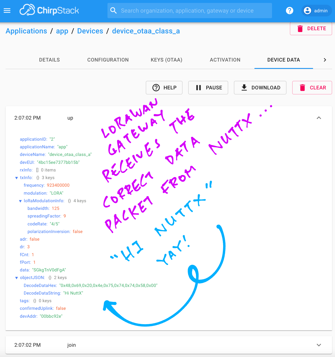
For troubleshooting tips, see this…
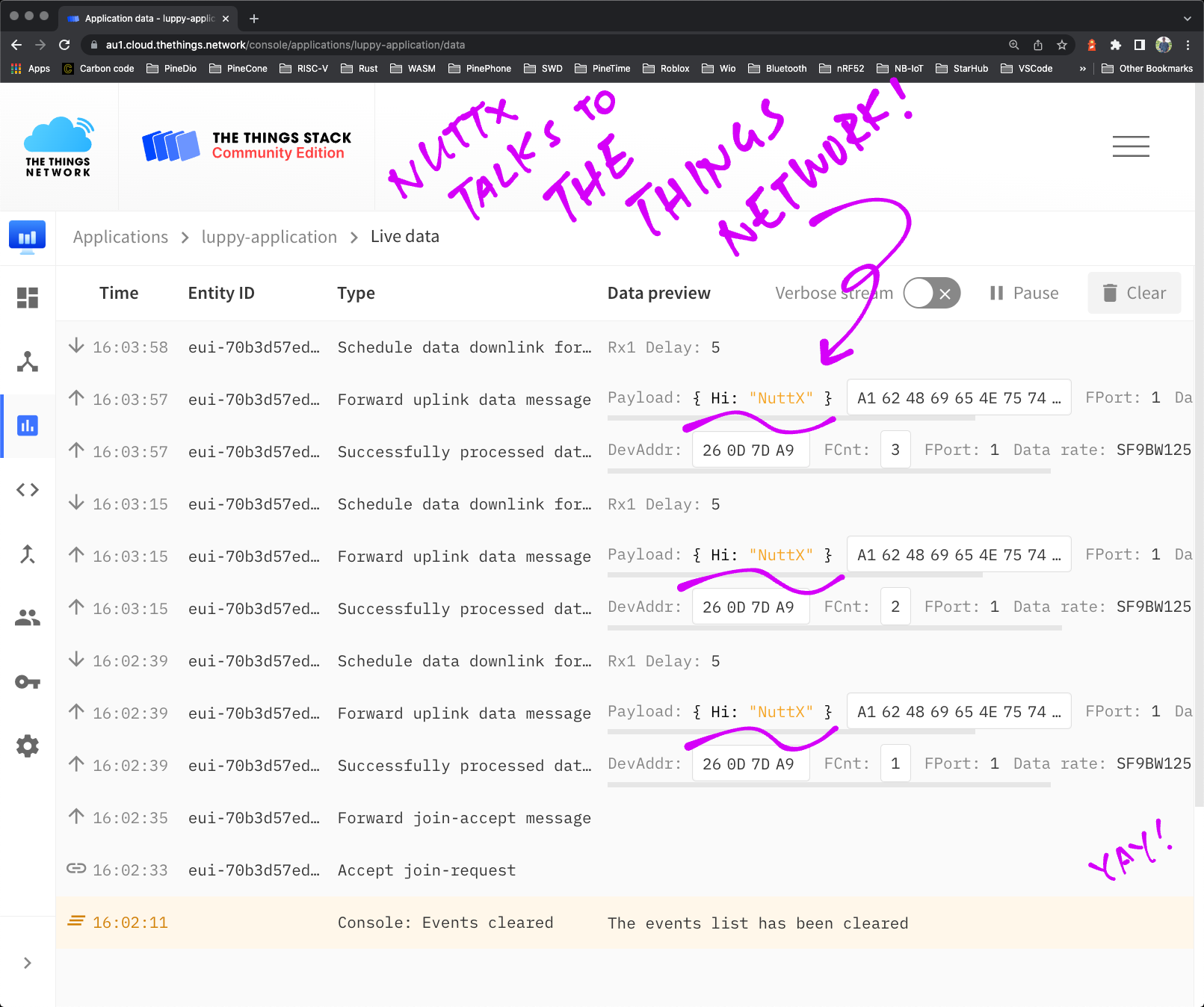
Will PineDio Stack connect to The Things Network?
Yes just set the LoRaWAN Parameters like so…
LORAWAN_DEVICE_EUI: Set this to the DevEUI from The Things Network
LORAWAN_JOIN_EUI: Set this to { 0x00, 0x00, 0x00, 0x00, 0x00, 0x00, 0x00, 0x00 }
APP_KEY, NWK_KEY: Set both to the AppKey from The Things Network
To get the DevEUI and AppKey from The Things Network…
(I don’t think NWK_KEY is used)
NuttX transmits a CBOR Payload to The Things Network Over LoRaWAN
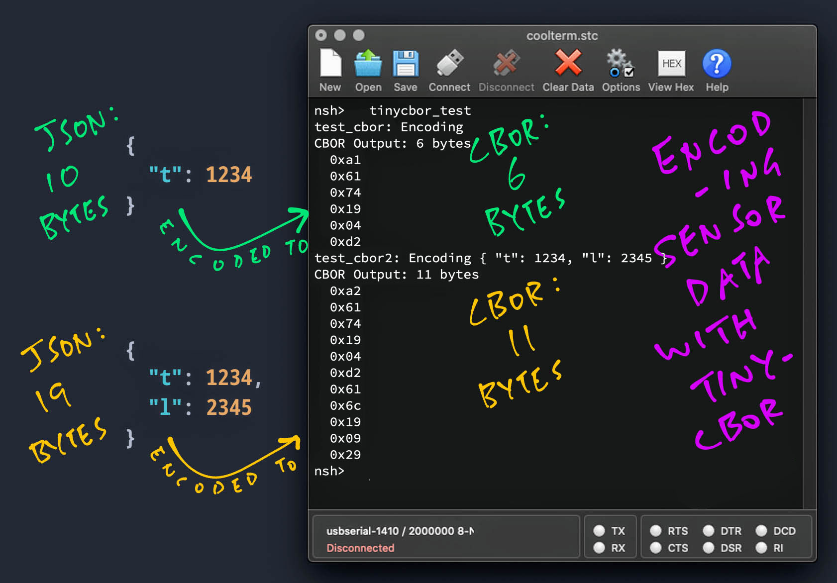
Suppose we’re creating an app that transmits Sensor Data over LoRa (or LoRaWAN) from two sensors: Temperature Sensor and Light Sensor…
{
  "t": 1234,
  "l": 2345
}
(Located in a Greenhouse perhaps)
We could transmit 19 bytes of JSON. But there’s a more compact way to do it….
Concise Binary Object Representation (CBOR), which works like a binary, compressed form of JSON.
And we need only 11 bytes of CBOR!
To watch CBOR in action, enter this in the NuttX Shell…
tinycbor_testWe’ll see the encoded CBOR data…
test_cbor2: Encoding { "t": 1234, "l": 2345 }
CBOR Output: 11 bytes
  0xa2
  0x61
  0x74
  0x19
  0x04
  0xd2
  0x61
  0x6c
  0x19
  0x09
0x29To encode CBOR data in our own apps, check out this article…
CBOR Decoding can be done automatically in The Things Network…
We can visualise the Sensor Data with open-source Grafana and Prometheus…
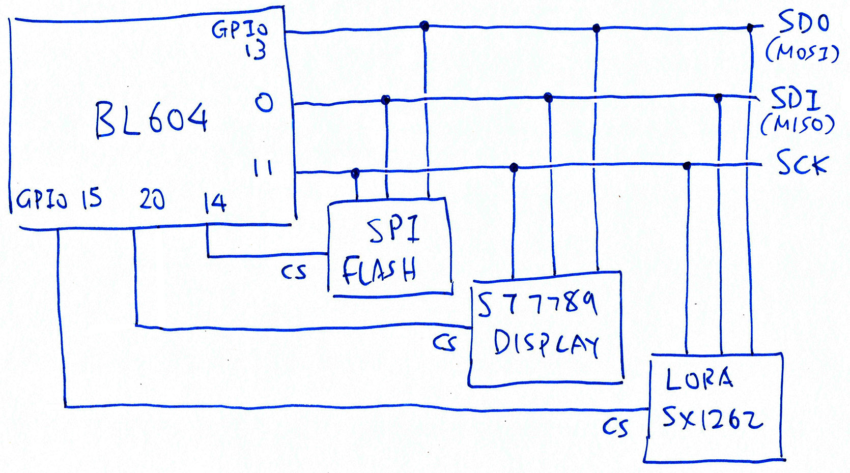
This section explains how we modified NuttX to handle the Shared SPI Bus on PineDio Stack BL604.
Acording to the PineDio Stack Schematics…
The SPI Bus is shared by…
ST7789 Display Controller
Semtech SX1262 LoRa Transceiver
SPI Flash
Here are the BL604 GPIO Numbers for the shared SPI Bus…
| Function | GPIO |
|---|---|
| SPI MOSI | 13 |
| SPI MISO | 0 |
| SPI SCK | 11 |
| SPI CS (Unused) | 8 |
To prevent crosstalk, we select each SPI Device by flipping its Chip Select Pin from High to Low…
| SPI Device | Device ID | Swap MISO/MOSI | Chip Select |
|---|---|---|---|
| ST7789 Display | 0x40000 | No | 20 |
| SX1262 Transceiver | 1 | Yes | 15 |
| SPI Flash | 2 | Yes | 14 |
| (Default Device) | -1 | Yes | 8 (Unused) |
How is Chip Select implemented in NuttX?
To select (or deselect) an SPI Device, NuttX calls these functions provided by the BL602 / BL604 SPI Driver…
bl602_spi_lock: Lock (or unlock) the SPI Bus with a Semaphore
bl602_spi_select: Flip the Chip Select Pin to Low (or High)
However the SPI Driver doesn’t support multiple Chip Select Pins. (See this)
Here’s how we modded the SPI Driver for PineDio Stack…
What’s the SPI Device ID in the table above?
We identify each SPI Device with a unique SPI Device ID.
NuttX passes the Device ID when it calls bl602_spi_select. We’ll use this to flip the right Chip Select Pin for the SPI Device.
How did we get the SPI Device IDs?
NuttX auto-assigns 0x40000 as the SPI Device ID for the ST7789 Display. (See this)
We assigned the other SPI Device IDs ourselves.
Device ID -1 is meant as a fallthrough to catch all SPI Devices that don’t match the Device IDs. This also works for simple SPI setups where the Device ID is not needed.
What’s the Swap MISO / MOSI column in the table above?
According to the BL602 / BL604 Reference Manual (Table 3.1 “Pin Description”, Page 26)…
GPIO 13 is designated as MOSI
GPIO 0 is designed as MISO
But due to a BL602 / BL604 SPI quirk we need to swap MISO and MOSI to get this behaviour. (See this)
That’s why the “Swap MISO / MOSI” column is marked “Yes” for SX1262 Transceiver and SPI Flash.
But ST7789 doesn’t swap MISO and MOSI?
The ST7789 Display Controller is wired differently on PineDio Stack…
ST7789 receives SPI Data on GPIO 0
ST7789 Data / Command Pin is connected on GPIO 13
(High for ST7789 Data, Low for ST7789 Commands)
The direction of SPI Data is flipped for ST7789.
That’s why the “Swap MISO / MOSI” column is marked “No” for the ST7789 Display Controller.
So we will swap and unswap MISO / MOSI on the fly?
Yep since we’ll run the ST7789, SX1262 and SPI Flash drivers concurrently, we’ll need to swap and unswap MISO / MOSI before every SPI operation.
We’ll do this in bl602_spi_select.
How do we store the SPI Device Table in NuttX?
We represent the above SPI Device Table in NuttX as a flat int array…
| SPI Device | Device ID | Swap MISO/MOSI | Chip Select |
|---|---|---|---|
| ST7789 Display | 0x40000 | 0 | 20 |
| SX1262 Transceiver | 1 | 1 | 15 |
| SPI Flash | 2 | 1 | 14 |
| (Default Device) | -1 | 1 | 8 |
Here’s the source code for the SPI Device Table…
#ifdef CONFIG_BL602_SPI0
/* SPI Device Table: SPI Device ID, Swap MISO/MOSI, Chip Select */

static const int32_t bl602_spi_device_table[] =
{
#ifdef BOARD_LCD_DEVID  /* ST7789 Display */
  BOARD_LCD_DEVID, BOARD_LCD_SWAP, BOARD_LCD_CS,
#endif  /* BOARD_LCD_DEVID */

#ifdef BOARD_SX1262_DEVID  /* LoRa SX1262 */
  BOARD_SX1262_DEVID, BOARD_SX1262_SWAP, BOARD_SX1262_CS,
#endif  /* BOARD_SX1262_DEVID */

#ifdef BOARD_FLASH_DEVID  /* SPI Flash */
  BOARD_FLASH_DEVID, BOARD_FLASH_SWAP, BOARD_FLASH_CS,
#endif  /* BOARD_FLASH_DEVID */

  /* Must end with Default SPI Device */

  -1, 1, BOARD_SPI_CS,  /* Swap MISO/MOSI */
};
#endif /* CONFIG_BL602_SPI0 */We’ll see the BOARD_* constants in the next section.
The columns of the SPI Device Table are defined like so…
/* Columns in the SPI Device Table */

#define DEVID_COL 0  /* SPI Device ID */
#define SWAP_COL  1  /* 1 if MISO/MOSI should be swapped, else 0 */
#define CS_COL    2  /* SPI Chip Select Pin */
#define NUM_COLS 3 /* Number of columns in SPI Device Table */We created these functions for accessing the SPI Device Table…
bl602_spi_get_device: Lookup a device in the SPI Device Table
(Called when selecting and deselecting devices)
bl602_spi_deselect_devices: Deselect all devices in the SPI Device Table
(Called during startup)
bl602_spi_validate_devices: Validate the devices in the SPI Device Table
(In case of coding errors)
Let’s look at the BOARD_* definitions.
Where are the SPI Pins defined?
The SPI Device Table above refers to the following Pin Definitions at boards/risc-v/bl602/bl602evb/include/board.h
/* SPI for PineDio Stack: Chip Select (unused), MOSI, MISO, SCK */

#define BOARD_SPI_CS   (GPIO_INPUT | GPIO_PULLUP | GPIO_FUNC_SPI | GPIO_PIN8)  /* Unused */
#define BOARD_SPI_MOSI (GPIO_INPUT | GPIO_PULLUP | GPIO_FUNC_SPI | GPIO_PIN13)
#define BOARD_SPI_MISO (GPIO_INPUT | GPIO_PULLUP | GPIO_FUNC_SPI | GPIO_PIN0)
#define BOARD_SPI_CLK  (GPIO_INPUT | GPIO_PULLUP | GPIO_FUNC_SPI | GPIO_PIN11)

#ifdef CONFIG_LCD_ST7789
/* ST7789 for PineDio Stack: Chip Select, Reset and Backlight */

#define BOARD_LCD_DEVID SPIDEV_DISPLAY(0)  /* SPI Device ID: 0x40000 */
#define BOARD_LCD_SWAP  0    /* Don't swap MISO/MOSI */
#define BOARD_LCD_BL_INVERT  /* Backlight is active when Low */
#define BOARD_LCD_CS  (GPIO_OUTPUT | GPIO_PULLUP | GPIO_FUNC_SWGPIO | GPIO_PIN20)
#define BOARD_LCD_RST (GPIO_OUTPUT | GPIO_PULLUP | GPIO_FUNC_SWGPIO | GPIO_PIN3)
#define BOARD_LCD_BL  (GPIO_OUTPUT | GPIO_PULLUP | GPIO_FUNC_SWGPIO | GPIO_PIN21)
#endif  /* CONFIG_LCD_ST7789 */

/* SX1262 for PineDio Stack: Chip Select */

#define BOARD_SX1262_DEVID 1  /* SPI Device ID */
#define BOARD_SX1262_SWAP  1  /* Swap MISO/MOSI */
#define BOARD_SX1262_CS (GPIO_OUTPUT | GPIO_PULLUP | GPIO_FUNC_SWGPIO | GPIO_PIN15)

/* SPI Flash for PineDio Stack: Chip Select */

#define BOARD_FLASH_DEVID 2  /* SPI Device ID */
#define BOARD_FLASH_SWAP  1  /* Swap MISO/MOSI */
#define BOARD_FLASH_CS (GPIO_OUTPUT | GPIO_PULLUP | GPIO_FUNC_SWGPIO | GPIO_PIN14)
(GPIO, UART and I2C Pins are also defined in the file)
Now that we have defined the SPI Device Table in NuttX, let’s use it.
Remember that NuttX calls bl602_spi_select to select (or deselect) an SPI Device.
For PineDio Stack, these are the changes we made to bl602_spi_select…
NuttX already passes the SPI Device ID when it calls bl602_spi_select
Based on the SPI Device ID, we look up the SPI Device Table
We swap MISO and MOSI as specified by the SPI Device Table
We flip the Chip Select Pin specified in the SPI Device Table
Here’s the implementation…
//  Enable/disable the SPI chip select
static void bl602_spi_select(struct spi_dev_s *dev, uint32_t devid,
                             bool selected)
{
  const int32_t *spidev;

  spiinfo("devid: %lu, CS: %s\n", devid, selected ? "select" : "free");

  /* get device from SPI Device Table */

  spidev = bl602_spi_get_device(devid);
  DEBUGASSERT(spidev != NULL);

  /* swap MISO and MOSI if needed */

  if (selected)
    {
      bl602_swap_spi_0_mosi_with_miso(spidev[SWAP_COL]);
    }

  /* set Chip Select */

  bl602_gpiowrite(spidev[CS_COL], !selected);

#ifdef CONFIG_SPI_CMDDATA
  /* revert MISO and MOSI from GPIO Pins to SPI Pins */

  if (!selected)
    {
      bl602_configgpio(BOARD_SPI_MISO);
      bl602_configgpio(BOARD_SPI_MOSI);
    }
#endif
}(bl602_gpiowrite is defined in the BL602 GPIO Driver)
(bl602_configgpio also comes from the BL602 GPIO Driver)
Let’s talk about CONFIG_SPI_CMDDATA…
NuttX RTOS uses MISO as the ST7789 Data / Command Pin. (See this)
(We flip the pin High for ST7789 Data, Low for ST7789 Commands)
But ST7789 is wired “backwards” on PineDio Stack BL604! We use MOSI as the ST7789 Data / Command Pin instead.
Here’s how we flip the ST7789 Data / Command pin depending on the “Swap MISO / MOSI” indicator in the SPI Device Table…
#ifdef CONFIG_SPI_CMDDATA
//  Called by NuttX to flip the ST7789 Data / Command Pin
static int bl602_spi_cmddata(struct spi_dev_s *dev,
                              uint32_t devid, bool cmd)
{
  spiinfo("devid: %" PRIu32 " CMD: %s\n", devid, cmd ? "command" :
          "data");

  if (devid == SPIDEV_DISPLAY(0))
    {
      const int32_t *spidev;
      gpio_pinset_t dc;
      gpio_pinset_t gpio;
      int ret;

      /* get device from SPI Device Table */

      spidev = bl602_spi_get_device(devid);
      DEBUGASSERT(spidev != NULL);

      /* if MISO/MOSI are swapped, DC is MISO, else MOSI */

      dc = spidev[SWAP_COL] ? BOARD_SPI_MISO : BOARD_SPI_MOSI;

      /* reconfigure DC from SPI Pin to GPIO Pin */

      gpio = (dc & GPIO_PIN_MASK)
             | GPIO_OUTPUT | GPIO_PULLUP | GPIO_FUNC_SWGPIO;
      ret = bl602_configgpio(gpio);
      if (ret < 0)
        {
          spierr("Failed to configure MISO as GPIO\n");
          DEBUGPANIC();

          return ret;
        }

      /* set DC to high (data) or low (command) */

      bl602_gpiowrite(gpio, !cmd);

      return OK;
    }

  spierr("SPI cmddata not supported\n");
  DEBUGPANIC();

  return -ENODEV;
}
#endif(bl602_configgpio is defined in the BL602 GPIO Driver)
(bl602_gpiowrite also comes from the BL602 GPIO Driver)
Note that we reconfigure MISO / MOSI from SPI Pins to GPIO Pins.
We revert MISO / MOSI back to SPI Pins when the SPI Device is deselected in bl602_spi_select.
At NuttX Startup, we deselect all SPI Devices by flipping their Chip Select Pins high (after validating the SPI Device Table)…
//  Called by NuttX to initialise the SPI Driver
static void bl602_spi_init(struct spi_dev_s *dev)
{
  /* Omitted: Init SPI port */
  ...
  /* spi fifo clear */

  modifyreg32(BL602_SPI_FIFO_CFG_0, SPI_FIFO_CFG_0_RX_CLR
              | SPI_FIFO_CFG_0_TX_CLR, 0);

  /* deselect all spi devices */

  bl602_spi_deselect_devices();
}(bl602_spi_deselect_devices is defined here)
But will this Shared SPI Bus work? Swapping MISO / MOSI on the fly while flipping multiple Chip Select Pins?
Yes the Shared SPI Bus works beautifully on PineDio Stack! This is how we tested with ST7789 Display and SX1262 Transceiver…
We boot PineDio Stack, which calls the ST7789 Driver to render a Pink Screen…
(Our SPI Driver unswaps MISO / MOSI, flips ST7789 Chip Select)
board_lcd_getdev: SPI port 0 bound to LCD 0
st7789_getplaneinfo: planeno: 0 bpp: 16Then we run the spi_test2 app to read a SX1262 Register over SPI…
(Our SPI Driver swaps MISO / MOSI, flips SX1262 Chip Select)
nsh> spi_test2
...
Read Register 8: received
a2 a2 a2 a2 80
SX1262 Register 8 is 0x80SX1262 returns Register Value 0x80, which is correct!
Finally we run the LVGL Demo App to access the ST7789 Display…
(Our SPI Driver unswaps MISO / MOSI, flips ST7789 Chip Select)
nsh> lvgldemo
st7789_getvideoinfo: fmt: 11 xres: 240 yres: 240 nplanes: 1
lcddev_init: VideoInfo:
  fmt: 11
  xres: 240
  yres: 240
  nplanes: 1
...
monitor_cb: 57600 px refreshed in 1110 msWhich renders the LVGL Demo Screen correctly!
BL602 / BL604 has another SPI Quirk that affects ST7789 on PineDio Stack…
BL602 / BL604 talks to ST7789 Display at SPI Mode 1 or Mode 3, depending on whether MISO / MOSI are swapped…
If MISO / MOSI are NOT Swapped:
Use SPI Mode 1
If MISO / MOSI are Swapped:
Use SPI Mode 3
Since MISO / MOSI are not swapped for ST7789 on PineDio Stack, we use SPI Mode 1. Here’s the implementation…
#ifdef CONFIG_BL602_SPI0
#include "../boards/risc-v/bl602/bl602evb/include/board.h"
#endif  /* CONFIG_BL602_SPI0 */

//  If ST7789 is enabled...
#ifdef CONFIG_LCD_ST7789

//  If this is BL602...
#ifdef CONFIG_BL602_SPI0

  //  If MISO/MOSI are not swapped...
  #if defined(BOARD_LCD_SWAP) && BOARD_LCD_SWAP == 0
    //  Use SPI Mode 1 as workaround for BL602
    #warning Using SPI Mode 1 for ST7789 on BL602 (MISO/MOSI not swapped)
    #define CONFIG_LCD_ST7789_SPIMODE SPIDEV_MODE1

  //  If MISO/MOSI are swapped...
  #else
    //  Use SPI Mode 3 as workaround for BL602
    #warning Using SPI Mode 3 for ST7789 on BL602 (MISO/MOSI swapped)
    #define CONFIG_LCD_ST7789_SPIMODE SPIDEV_MODE3
  #endif /* BOARD_LCD_SWAP */

//  If this is not BL602...
#else

  //  Use the SPI Mode specified in menuconfig
  #ifndef CONFIG_LCD_ST7789_SPIMODE
  #define CONFIG_LCD_ST7789_SPIMODE SPIDEV_MODE0
  #endif   /* CONFIG_LCD_ST7789_SPIMODE */

#endif /* CONFIG_BL602_SPI0 */Note that we have configured PineDio Stack to talk to SX1262 at SPI Mode 1 via the SPI Test Driver “/dev/spitest0”. (See this)
We have configured the SPI Frequency of the ST7789 Display to 40 MHz, the maximum supported by BL604…
CONFIG_LCD_ST7789_FREQUENCY=4000000We configured the SPI Frequency in menuconfig at…
In future we should implement SPI with Direct Memory Access (DMA) to avoid busy-polling the SPI Bus. (See this)
Hopefully this will improve the responsiveness of the touchscreen.
UPDATE: SPI DMA is now supported on BL602 / BL604 NuttX…
There’s a potential Race Condition if we use the SX1262 Driver concurrently with the ST7789 Driver…
During LoRa Transmission, SX1262 Driver calls ioctl() to flip SX1262 Chip Select to Low
SX1262 Driver calls SPI Test Driver “/dev/spitest0”, which locks (SPI_LOCK) and selects (SPI_SELECT) the SPI Bus (with SPI Device ID 0)
Note that the calls to ioctl() and SPI_LOCK / SPI_SELECT are NOT Atomic
If the ST7789 Driver is active between the calls to ioctl() and SPI_LOCK / SPI_SELECT, both SX1262 Chip Select and ST7789 Chip Select will be flipped to Low
This might transmit garbage to SX1262
To solve this problem, we will register a new SPI Test Driver “/dev/spitest1” with SPI Device ID 1. (With some tweaks to the driver code)
The LoRa Driver will be modified to access “/dev/spitest1”, which will call SPI_LOCK and SPI_SELECT with SPI Device ID 1.
Since the SPI Device ID is 1, SPI_SELECT will flip the SX1262 Chip Select to Low.