📝 2 Apr 2022
ST7789 SPI Display connected to Pine64 PineCone BL602 RISC-V Board
Sitronix ST7789 is an SPI Display Controller that’s found in many gadgets. (Like PineTime Smartwatch)
LVGL is a popular Open-Source Library that renders text and graphics on Embedded Devices.
Today we shall run ST7789 Display and LVGL Library on Apache NuttX RTOS (Real-Time Operating System).
NuttX supports ST7789 and LVGL right out of the box. (Batteries all included!) So this tutorial should be breezy squeezy peasy.
We’ll run this tutorial on the BL602 RISC-V SoC and fix some issues specific to BL602…
SPI Send didn’t work correctly on BL602
ST7789 Data / Command Pin wasn’t implemented on BL602
BL602 only talks SPI Mode 3 to ST7789
The same steps should work on ESP32 and other NuttX Platforms. (Without the BL602 quirks)
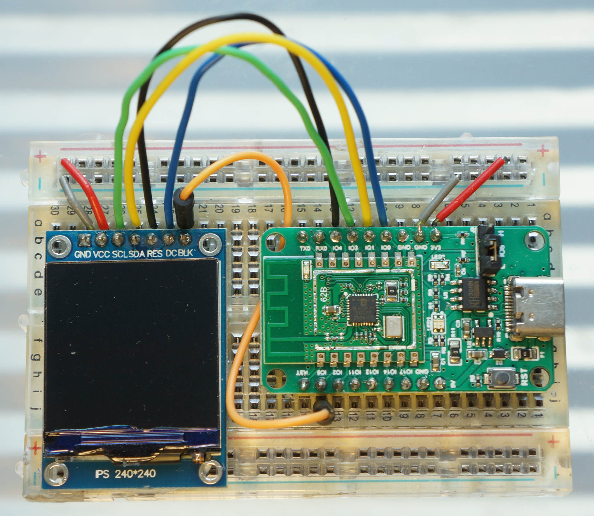
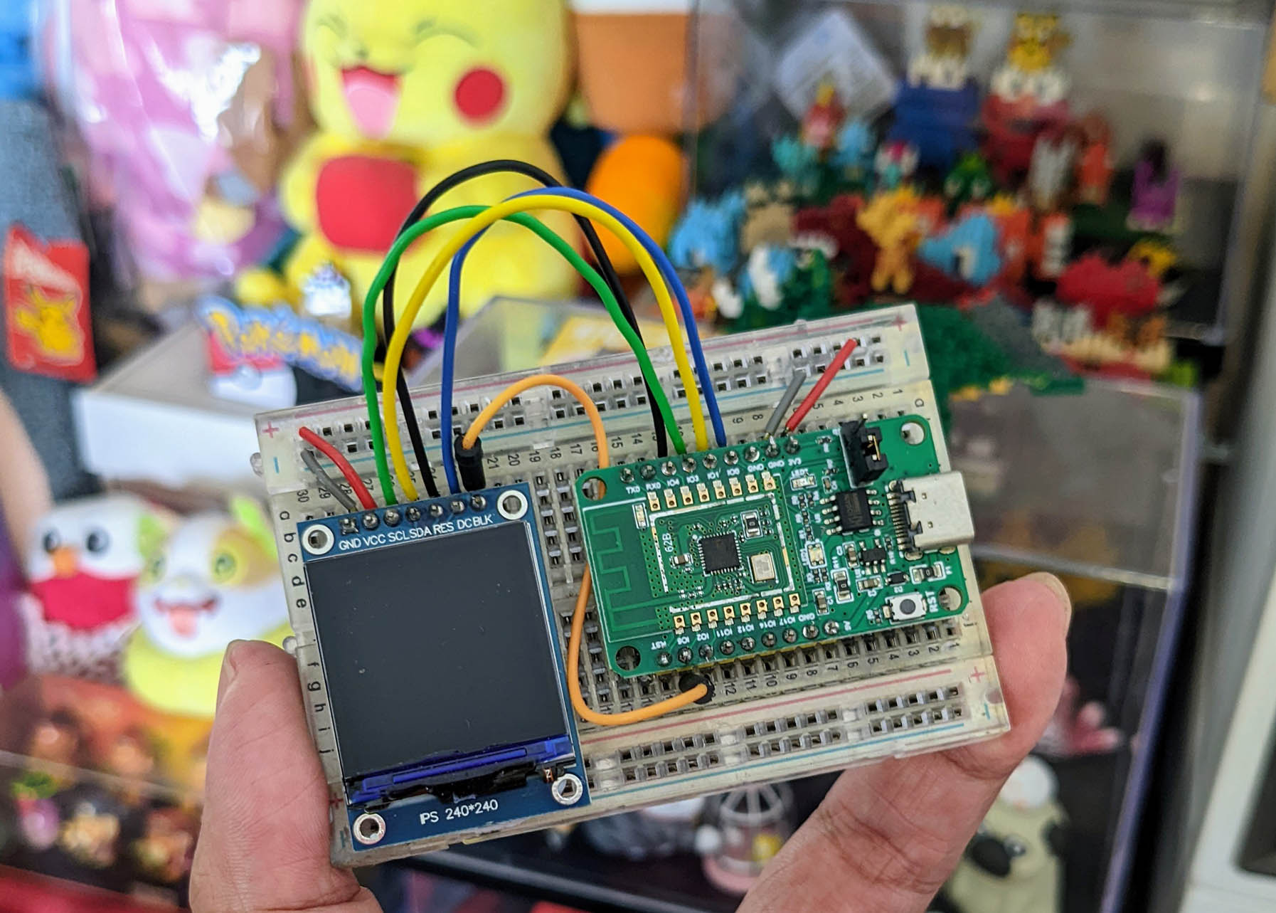
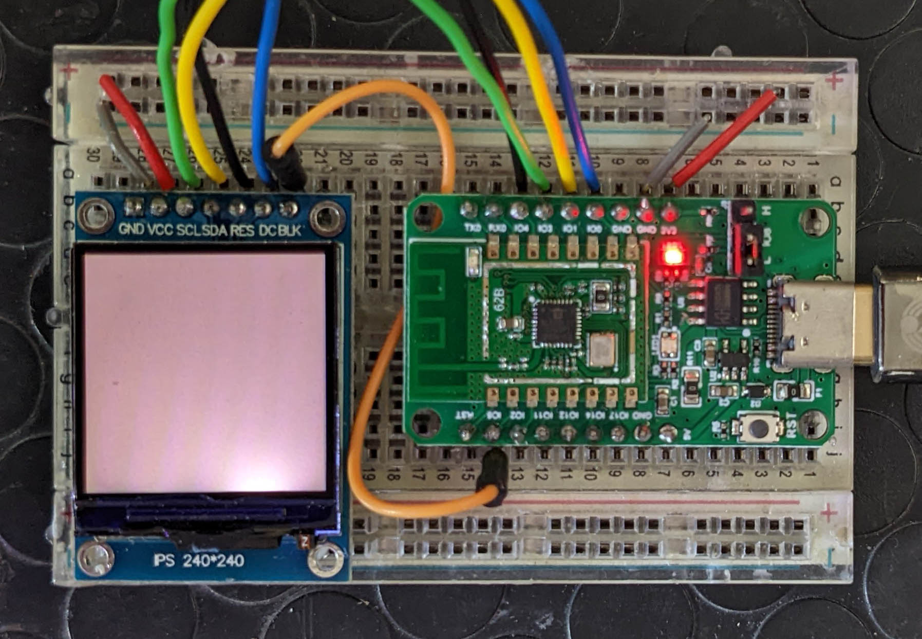
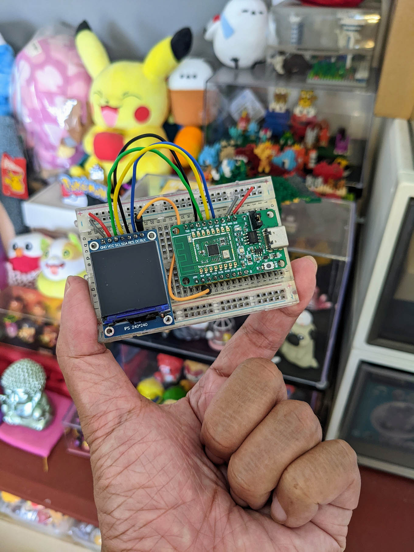
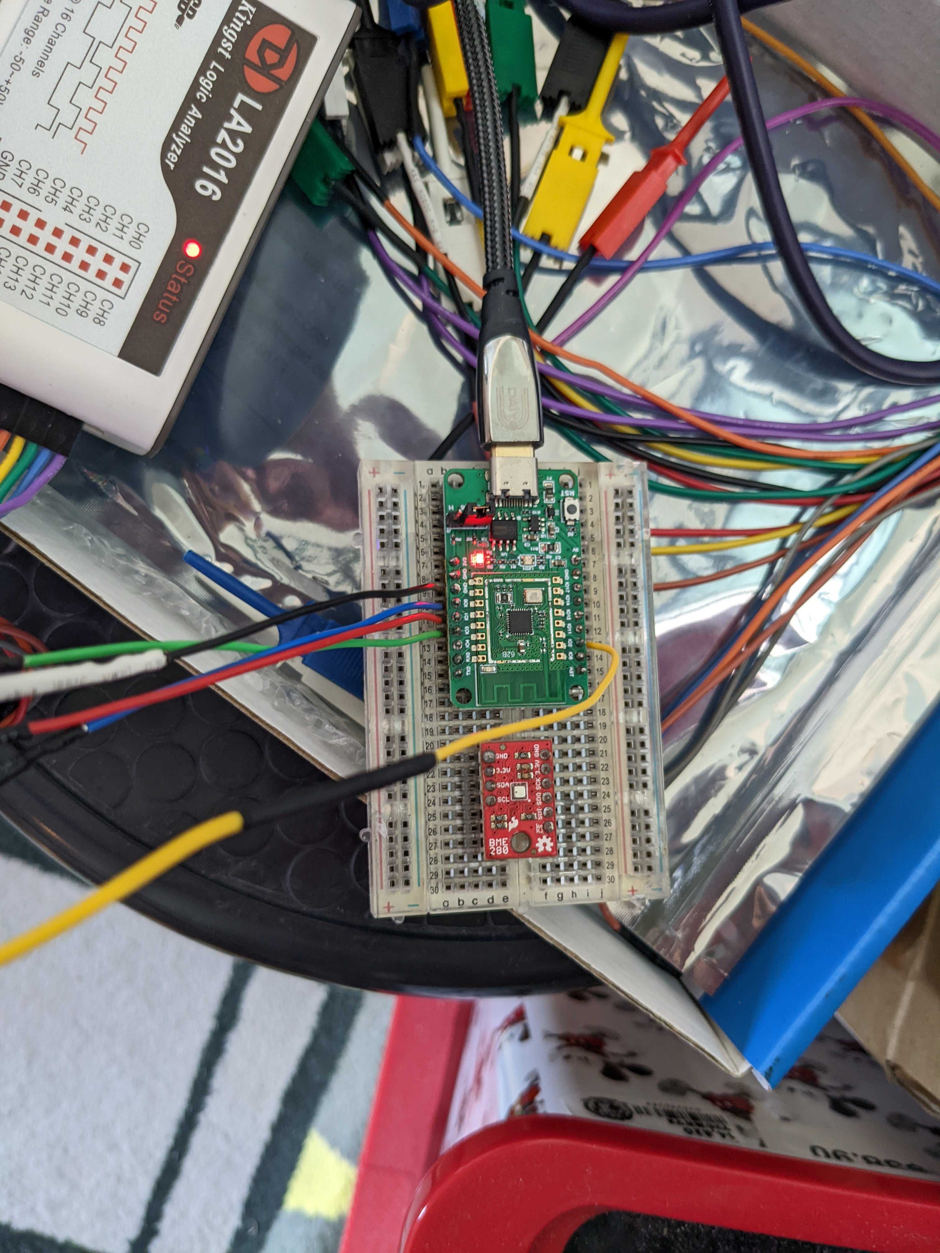
We connect the ST7789 SPI Display to BL602 as follows (pic above)…
| BL602 Pin | ST7789 SPI | Wire Colour |
|---|---|---|
GPIO 0 | DC (MISO) | Blue |
GPIO 2 | Unused (CS) | |
GPIO 1 | SDA (MOSI) | Yellow |
GPIO 3 | SCL (SCK) | Green |
GPIO 4 | RST (Reset) | Black |
GPIO 5 | BLK (Backlight) | Orange |
3V3 | 3.3V | Red |
GND | GND | Grey |
The BL602 pins for ST7789 are defined in board.h
/* SPI Configuration: For PineCone BL602 */

#define BOARD_SPI_CS   (GPIO_INPUT | GPIO_PULLUP | GPIO_FUNC_SPI | GPIO_PIN2)
#define BOARD_SPI_MOSI (GPIO_INPUT | GPIO_PULLUP | GPIO_FUNC_SPI | GPIO_PIN1)
#define BOARD_SPI_MISO (GPIO_INPUT | GPIO_PULLUP | GPIO_FUNC_SPI | GPIO_PIN0)
#define BOARD_SPI_CLK  (GPIO_INPUT | GPIO_PULLUP | GPIO_FUNC_SPI | GPIO_PIN3)

#ifdef CONFIG_LCD_ST7789
/* ST7789 Configuration: Reset and Backlight Pins */

#define BOARD_LCD_RST (GPIO_OUTPUT | GPIO_PULLUP | GPIO_FUNC_SWGPIO | GPIO_PIN4)
#define BOARD_LCD_BL  (GPIO_OUTPUT | GPIO_PULLUP | GPIO_FUNC_SWGPIO | GPIO_PIN5)
#endif  /* CONFIG_LCD_ST7789 */
(Which pins can be used? See this)
What if we’re connecting to ESP32-C3?
For ESP32-C3: The SPI Pins are defined in Kconfig and menuconfig…
config ESP32C3_SPI2_CSPIN
	default 10

config ESP32C3_SPI2_CLKPIN
	default 6

config ESP32C3_SPI2_MOSIPIN
	default 7

config ESP32C3_SPI2_MISOPIN
	default 2
The Reset and Backlight Pins are also defined in Kconfig and menuconfig…
config ESP32C3_LCD_RSTPIN
	int "LCD reset pin"
	default 9

config ESP32C3_LCD_BLPIN
	int "LCD backlight pin"
	default 18
(ESP32-C3 pins are referenced here)
To run ST7789 Display and LVGL Library on NuttX, download the modified source code for NuttX OS and NuttX Apps…
mkdir nuttx
cd nuttx
git clone --recursive --branch st7789 https://github.com/lupyuen/nuttx nuttx
git clone --recursive --branch st7789 https://github.com/lupyuen/nuttx-apps apps
(We’ll cover the modifications in the following sections)
Or if we have an existing NuttX Project, apply the following patches for ST7789 Display…
(For PineDio Stack BL604: The patches are already preinstalled)
Edit boards/risc-v/bl602/bl602evb/include/board.h and define the ST7789 pins…
Edit boards/risc-v/bl602/bl602evb/src/bl602_bringup.c and load the LCD Driver and the ST7789 Driver…
Edit drivers/lcd/st7789.c and configure ST7789 for SPI Mode 3…
(We’ll cover the patches in the following sections)
What’s the DC Pin on ST7789?
That’s the Data / Command Pin that tells ST7789 whether we’re sending data or commands to the display.
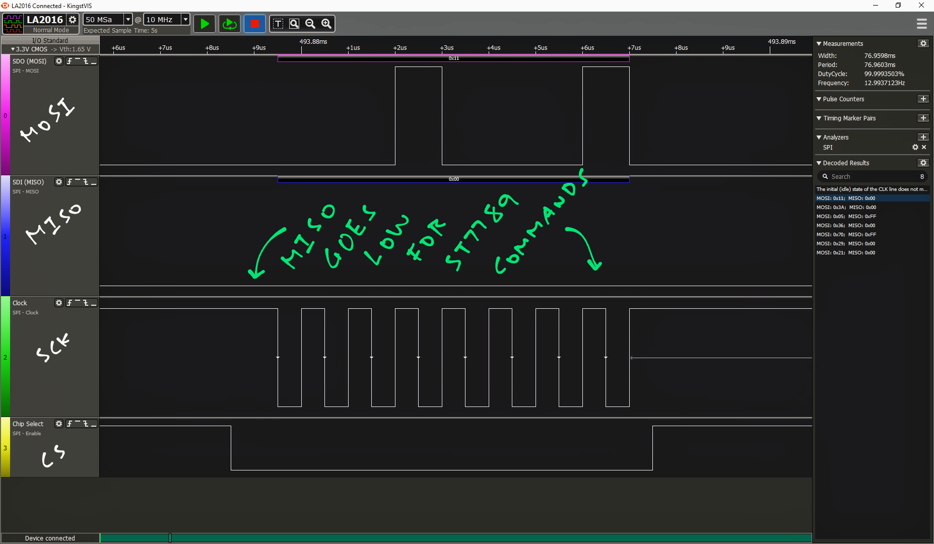
The Data / Command Pin goes Low when we’re sending ST7789 Commands…
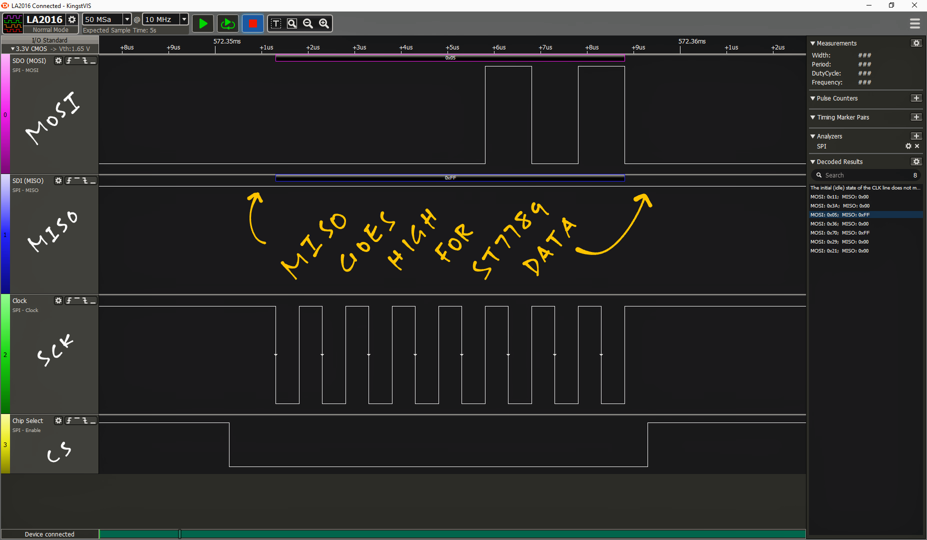
And goes High when we’re sending ST7789 Data…
So MISO talks to the Data / Command Pin?
Yep NuttX uses the SPI MISO Pin to control the ST7789 Data / Command Pin, as seen in the SPI Driver for ESP32-C3…
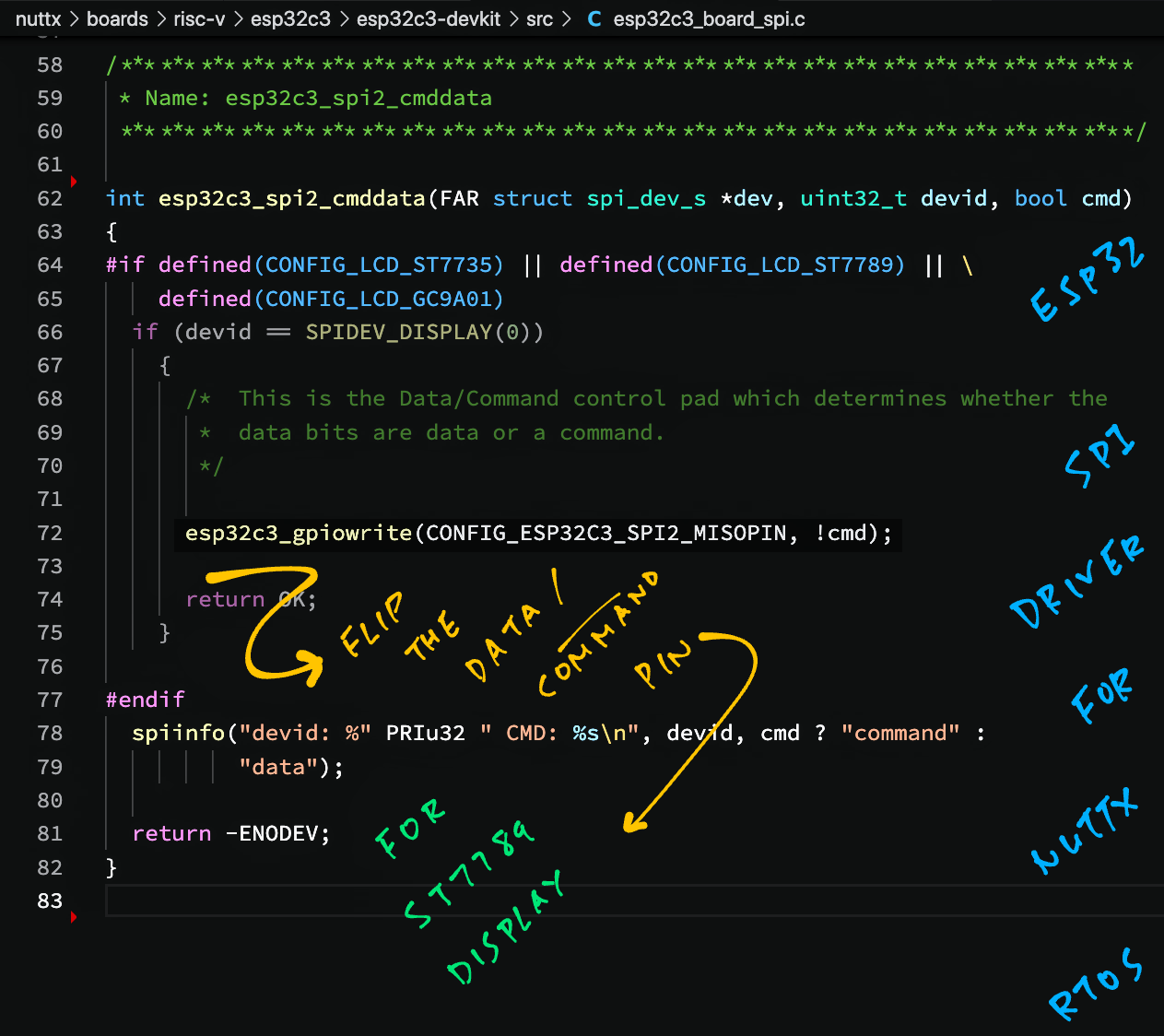
It flips the MISO Pin as though it was a GPIO Pin!
Can we do the same on BL602?
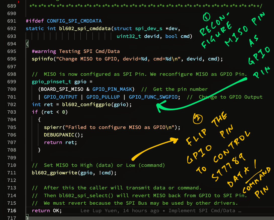
Yes but we need to reconfigure the SPI MISO Pin as a GPIO Pin, on the fly, before flipping it as a GPIO Pin…
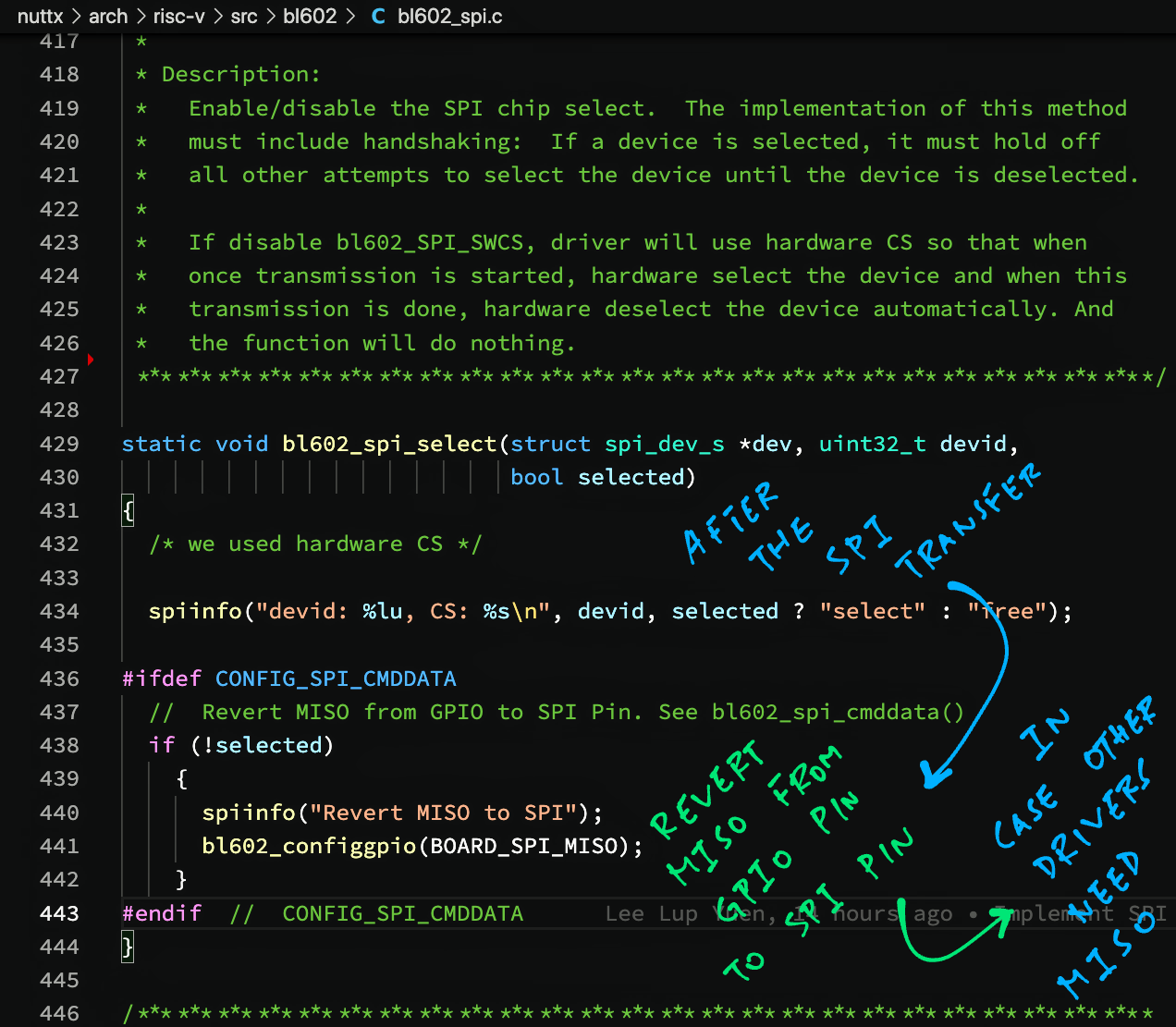
After sending ST7789 Command or Data, we revert the pin back from GPIO Pin to SPI MISO Pin…
Why must we revert the pin from GPIO back to SPI?
We must revert because the SPI Bus may be shared by other SPI Drivers that expect a functioning SPI MISO Pin.
(Like the Semtech SX1262 Driver on PineDio Stack BL604)
This nifty implementation of the Data / Command Pin has been merged into NuttX Mainline. (See this)
(For implementation details, see the Appendix)
While testing the ST7789 Driver, we hit a strange problem…
Our BL602 device would hang when sending anything over SPI to ST7789!
Can you spot the bug in bl602_spi_poll_send?
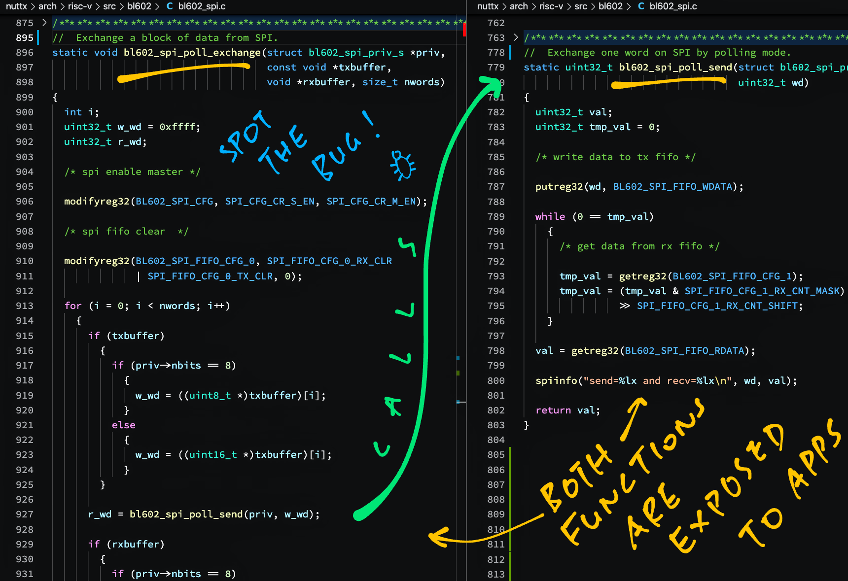
Answer: If we call SPI Poll Send (bl602_spi_poll_send) directly instead of SPI Poll Exchange (bl602_spi_poll_exchange)…
The SPI Port won’t get configured correctly!
(“SPI Enable Master” and “SPI FIFO Clear” are skipped)
And it hangs!
(Looping forever waiting for SPI FIFO)
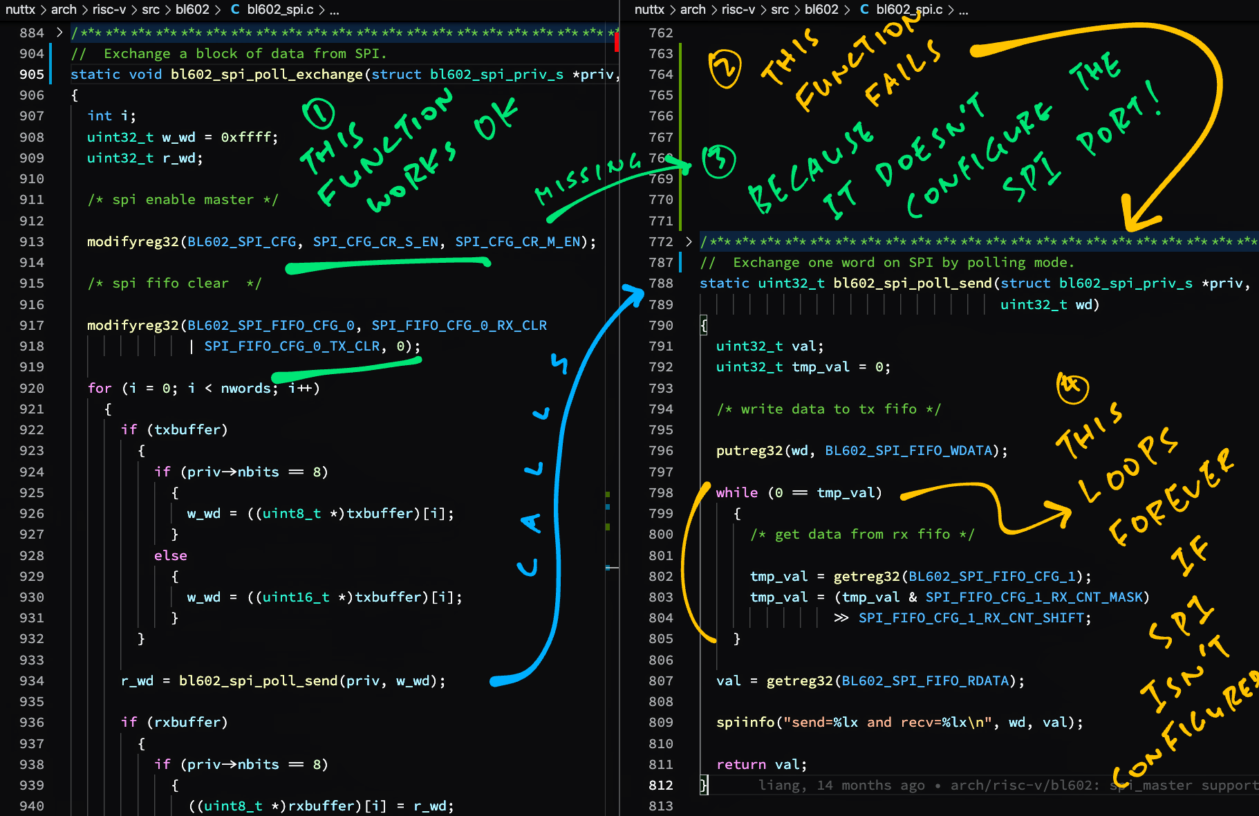
We fix this problem by moving the code that configures the SPI Port from SPI Poll Exchange to SPI Poll Send…
(Note that SPI Poll Exchange calls SPI Poll Send)
//  SPI Poll Send: Send the byte or word to the SPI Port
static uint32_t bl602_spi_poll_send(struct bl602_spi_priv_s *priv, uint32_t wd) {

  //  Enable SPI Master (moved from SPI Poll Exchange)
  modifyreg32(BL602_SPI_CFG, SPI_CFG_CR_S_EN, SPI_CFG_CR_M_EN);

  //  Clear SPI FIFO (moved from SPI Poll Exchange)
  modifyreg32(BL602_SPI_FIFO_CFG_0, SPI_FIFO_CFG_0_RX_CLR | SPI_FIFO_CFG_0_TX_CLR, 0);

  //  Rest of the function is the same...
  //  Write data to Transmit FIFO
  putreg32(wd, BL602_SPI_FIFO_WDATA);

  //  Wait for Receive FIFO and receive data
while (0 == tmp_val) { ... }After fixing, we verify with a Logic Analyser that SPI Poll Send transmits data correctly to ST7789…
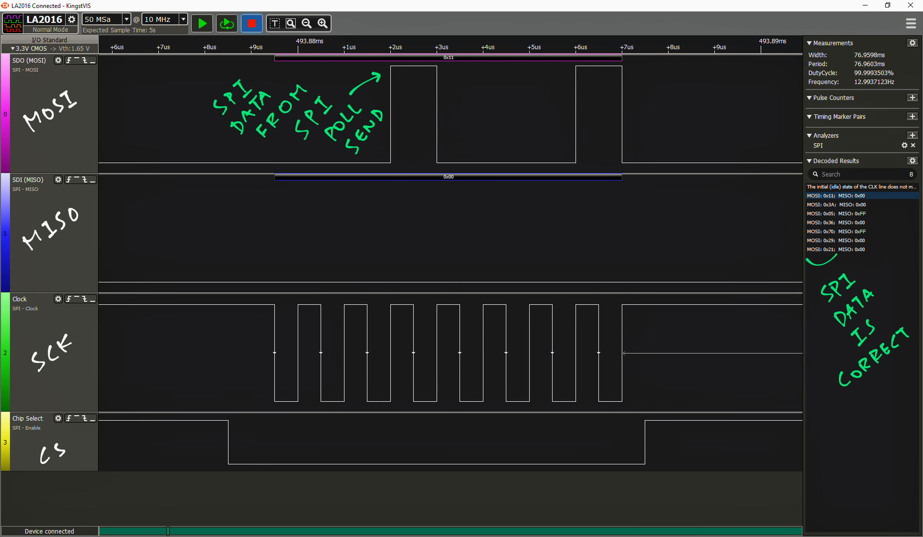
SPI Poll Send has been fixed in NuttX Mainline. (See this)
(For details of the fix, see the Appendix)
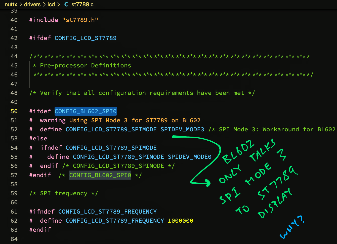
For some unknown reason, BL602 talks to ST7789 only in SPI Mode 3.
We hardcode SPI Mode 3 in the ST7789 Driver: st7789.c
//  If this is BL602...
#ifdef CONFIG_BL602_SPI0
  //  Use SPI Mode 3 as workaround for BL602
  #warning Using SPI Mode 3 for ST7789 on BL602
  #define CONFIG_LCD_ST7789_SPIMODE SPIDEV_MODE3

//  If not BL602...
#else
  //  Use SPI Mode 0 or from menuconfig
  #ifndef CONFIG_LCD_ST7789_SPIMODE
  #define CONFIG_LCD_ST7789_SPIMODE SPIDEV_MODE0
  #endif  //  CONFIG_LCD_ST7789_SPIMODE
#endif    //  CONFIG_BL602_SPI0
We’ve seen this behaviour with ST7789 and BL602 IoT SDK, so it’s probably a quirk in BL602’s SPI Port, not in the ST7789 Driver.
UPDATE: BL602 talks to ST7789 in SPI Mode 1 or Mode 3, depending on whether the MISO / MOSI Pins are swapped. (See this)
We fixed the SPI issues on BL602… Now we can load the ST7789 Driver at startup!
We do this in 2 steps…
We load the LCD Driver “/dev/lcd0”
Then we load the ST7789 Driver
(Which will be exposed to apps through the LCD Driver)
This is how we load the LCD Driver at startup: bl602_bringup.c
#ifdef CONFIG_LCD_DEV
#include <nuttx/board.h>
#include <nuttx/lcd/lcd_dev.h>
#endif  //  CONFIG_LCD_DEV

#ifdef CONFIG_LCD_ST7789
#include <nuttx/lcd/st7789.h>
#include "../boards/risc-v/bl602/bl602evb/include/board.h"
#include "riscv_internal.h"
#endif  //  CONFIG_LCD_ST7789
...
//  Called during NuttX startup to load drivers
int bl602_bringup(void) {
  ...
#ifdef CONFIG_LCD_DEV
  //  Initialize the LCD driver
  ret = board_lcd_initialize();
  if (ret < 0) {
    _err("ERROR: board_lcd_initialize() failed: %d\n", ret);
  }

  //  Register the LCD driver
  ret = lcddev_register(0);
  if (ret < 0) {
    _err("ERROR: lcddev_register() failed: %d\n", ret);
  }
#endif  //  CONFIG_LCD_DEV
  return ret;
}
bl602_bringup is called by NuttX during startup to load NuttX Drivers…
We call board_lcd_initialize to initialise the LCD Driver
(We’ll see this in a while)
Then we call lcddev_register to register the LCD Driver as “/dev/lcd0”
Which calls board_lcd_getdev to load the ST7789 Driver
Let’s study board_lcd_initialize and board_lcd_getdev
board_lcd_initialize initialises the LCD Driver at startup: bl602_bringup.c
#ifdef CONFIG_LCD_ST7789

//  SPI Port Number for LCD
#define LCD_SPI_PORTNO 0

//  SPI Bus for LCD
static struct spi_dev_s *st7789_spi_bus;

//  LCD Device
static struct lcd_dev_s *g_lcd = NULL;

//  Called by bl602_bringup during NuttX startup
//  to init the LCD Driver
int board_lcd_initialize(void) {
  //  Fetch the SPI Bus for the LCD Driver
  st7789_spi_bus = bl602_spibus_initialize(LCD_SPI_PORTNO);
  if (!st7789_spi_bus) {
    lcderr("ERROR: Failed to initialize SPI port %d for LCD\n", LCD_SPI_PORTNO);
    return -ENODEV;
  }

  //  Pull Reset Pin high to reset ST7789
  bl602_configgpio(BOARD_LCD_RST);        //  Configure Reset as GPIO Pin
  bl602_gpiowrite(BOARD_LCD_RST, false);  //  Set to Low
  up_mdelay(1);                           //  Wait 1 millisecond
  bl602_gpiowrite(BOARD_LCD_RST, true);   //  Set to High
  up_mdelay(10);                          //  Wait 10 milliseconds

  //  Set Backlight to full brightness
  bl602_configgpio(BOARD_LCD_BL);       //  Configure Backlight as GPIO Pin
  bl602_gpiowrite(BOARD_LCD_BL, true);  //  Set to High
  return OK;
}
Inside this function we…
Fetch the SPI Bus from NuttX
(Will be used by ST7789 Driver)
Flip the Reset Pin to Low then High
(To reset the ST7789 Display)
Switch on the Backlight
(So we can see things on the screen)
Finally we load the ST7789 Driver: bl602_bringup.c
//  Called by lcddev_register during NuttX startup
//  to load the ST7789 Driver
FAR struct lcd_dev_s *board_lcd_getdev(int devno) {
  //  Init the ST7789 driver
  g_lcd = st7789_lcdinitialize(st7789_spi_bus);

  //  Return the ST7789 driver
  if (!g_lcd) {
    lcderr("ERROR: Failed to bind SPI port %d to LCD %d\n", LCD_SPI_PORTNO,
      devno);
  } else {
    lcdinfo("SPI port %d bound to LCD %d\n", LCD_SPI_PORTNO, devno);
    return g_lcd;
  }
  return NULL;
}
#endif  //  CONFIG_LCD_ST7789
(We’ll see st7789_lcdinitialize later)
We initialise the ST7789 Driver and return it to lcddev_register…
Which will wrap the ST7789 Driver inside our LCD Driver “/dev/lcd0”.
That’s how we load the LCD Driver and ST7789 Driver on NuttX!
What about ESP32-C3?
For ESP32-C3: This is how we load the LCD Driver and ST7789 Driver at startup…
In a while we’ll boot NuttX to load the ST7789 Driver but…
How will we know if the ST7789 Driver is really working?
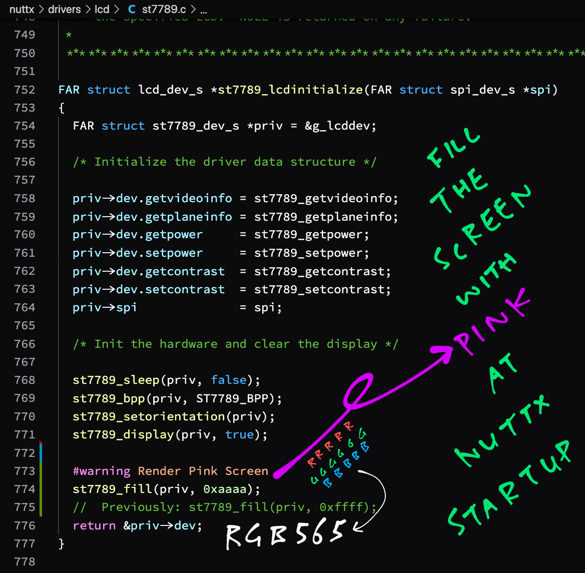
Here’s an idea… Let’s render a Pink Screen at startup!
This is how we do it: st7789.c
//  Called by board_lcd_getdev during NuttX startup
//  to init the ST7789 driver
FAR struct lcd_dev_s *st7789_lcdinitialize(FAR struct spi_dev_s *spi) {
  ...
  //  Disable sleep mode
  st7789_sleep(priv, false);

  //  Set to 16-bit colour
  st7789_bpp(priv, ST7789_BPP);

  //  Set display orientation
  st7789_setorientation(priv);

  //  Enable display
  st7789_display(priv, true);

  //  Fill the screen with pink
  st7789_fill(priv, 0xAAAA);

  //  Previously: Fill the screen with white
  //  st7789_fill(priv, 0xFFFF);
Recalls that st7789_lcdinitialize is called by board_lcd_getdev during NuttX startup.
This function initialises the ST7789 Display. We changed the last line so that it fills the screen with pink. (Colour value AAAA)
Let’s talk about AAAA…
Why is AAAA pink?
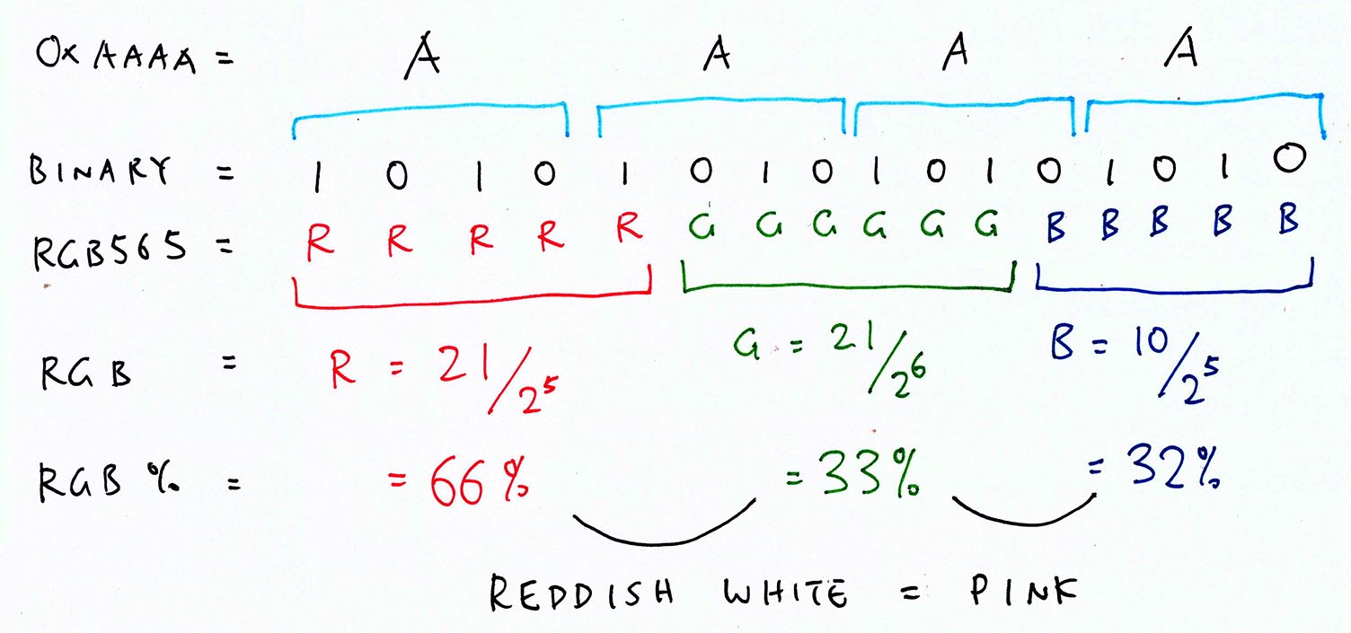
That’s because ST7789 encodes colours in 16 bits as RGB565…
5 bits for Red
6 bits for Green
5 bits for Blue
The pic above shows that AAAA broken down into RGB565 is…
66% Red
33% Green
32% Blue
Which is a reddish hue of white: pink!
We’re ready to boot NuttX and test the ST7789 Driver!
Follow these steps to build, flash and run NuttX (configured for ST7789 Driver)…
At the NuttX Shell, enter this command to list the NuttX Devices…
ls /devWe should see our LCD Device “/dev/lcd0”…
/dev:
 lcd0
...And our ST7789 Display should show a Pink Screen.
(Pic below)
Yep the ST7789 Driver works on NuttX!
The screen update looks laggy, hopefully we’ll fix this in 2 ways…
Increase the SPI Frequency from 1 MHz to 40 MHz, the maximum frequency supported by BL602
(In menuconfig: Device Drivers → LCD Driver Support → Graphic LCD Driver Support → LCD Driver Selection → Sitronix ST7789 → SPI Frequency)
Implement SPI Direct Memory Access (DMA) for faster transfers
UPDATE: SPI DMA is now supported on BL602 NuttX…
The ST7789 Driver works great on NuttX… Let’s render some graphics!
We’ll use the LVGL Graphics Library and LVGL Demo App bundled with NuttX.
Let’s look inside the LVGL Demo App: lvgldemo.c
// LVGL Demo App
int main(int argc, FAR char *argv[]) {
lv_disp_drv_t disp_drv;
lv_disp_buf_t disp_buf;
...
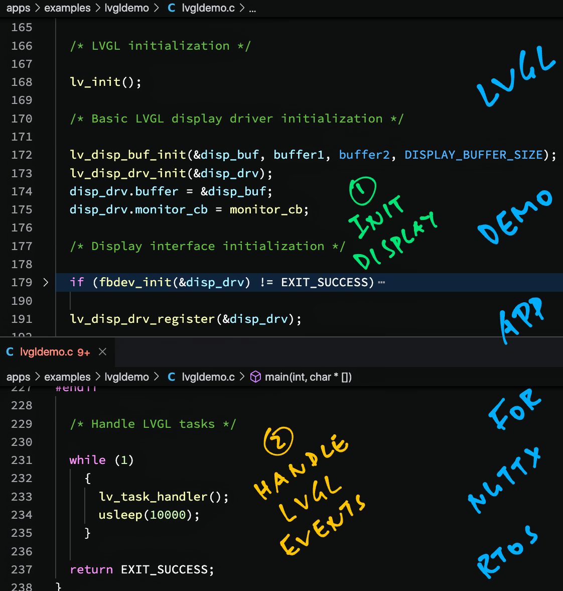
// LVGL initialization
lv_init();
// Basic LVGL display driver initialization
lv_disp_buf_init(&disp_buf, buffer1, buffer2, DISPLAY_BUFFER_SIZE);
lv_disp_drv_init(&disp_drv);
disp_drv.buffer = &disp_buf;
disp_drv.monitor_cb = monitor_cb;The app begins by initialising the LVGL Library.
NuttX supports 2 ways to access the display…
Frame Buffer Driver: “/dev/fb0”
LCD Driver: “/dev/lcd0”
  //  Display interface initialization
  if (fbdev_init(&disp_drv) != EXIT_SUCCESS) {
    //  Failed to use Frame Buffer, falling back to LCD Driver
    if (lcddev_init(&disp_drv) != EXIT_SUCCESS) {
      //  No possible drivers left, fail
      return EXIT_FAILURE;
    }
  }

  //  Register the display driver
  lv_disp_drv_register(&disp_drv);
For ST7789 we’ll use the LCD Driver.
Then we render some LVGL Widgets (UI controls)…
  //  Render the widgets
  lv_demo_widgets();
(We’ll see lv_demo_widgets later)
And we loop forever handling LVGL Events (like for display updates)…
  //  Loop forever handling LVGL tasks
  while (1) {
    lv_task_handler();  //  Handle LVGL tasks
    usleep(10000);      //  Sleep 10 milliseconds
  }
Let’s run this!
For our final demo today, we’ll run the LVGL Demo App that’s bundled with NuttX…
Follow these steps to build, flash and run NuttX (configured for LVGL Library and LVGL Demo)…
At the NuttX Shell, enter this command to run the LVGL Demo App…
lvgldemoWe see that the app initialises the ST7789 Display…
fbdev_init: Failed to open /dev/fb0: 2
st7789_getvideoinfo: fmt: 11 xres: 240 yres: 240 nplanes: 1
lcddev_init: VideoInfo:
  fmt: 11
  xres: 240
  yres: 240
  nplanes: 1
lcddev_init: PlaneInfo (plane 0):
  bpp: 16
The app says it can’t open the Frame Buffer Driver “/dev/fb0”. But that’s OK because it uses the LCD Driver “/dev/lcd0”.
Then the app paints the ST7789 Display in batches of 20 Pixel Rows (240 horizontal pixels each)…
st7789_putarea: row_start:  0 row_end: 19 col_start: 0 col_end: 239
st7789_putarea: row_start: 20 row_end: 39 col_start: 0 col_end: 239
...
st7789_putarea: row_start: 220 row_end: 239 col_start: 0 col_end: 239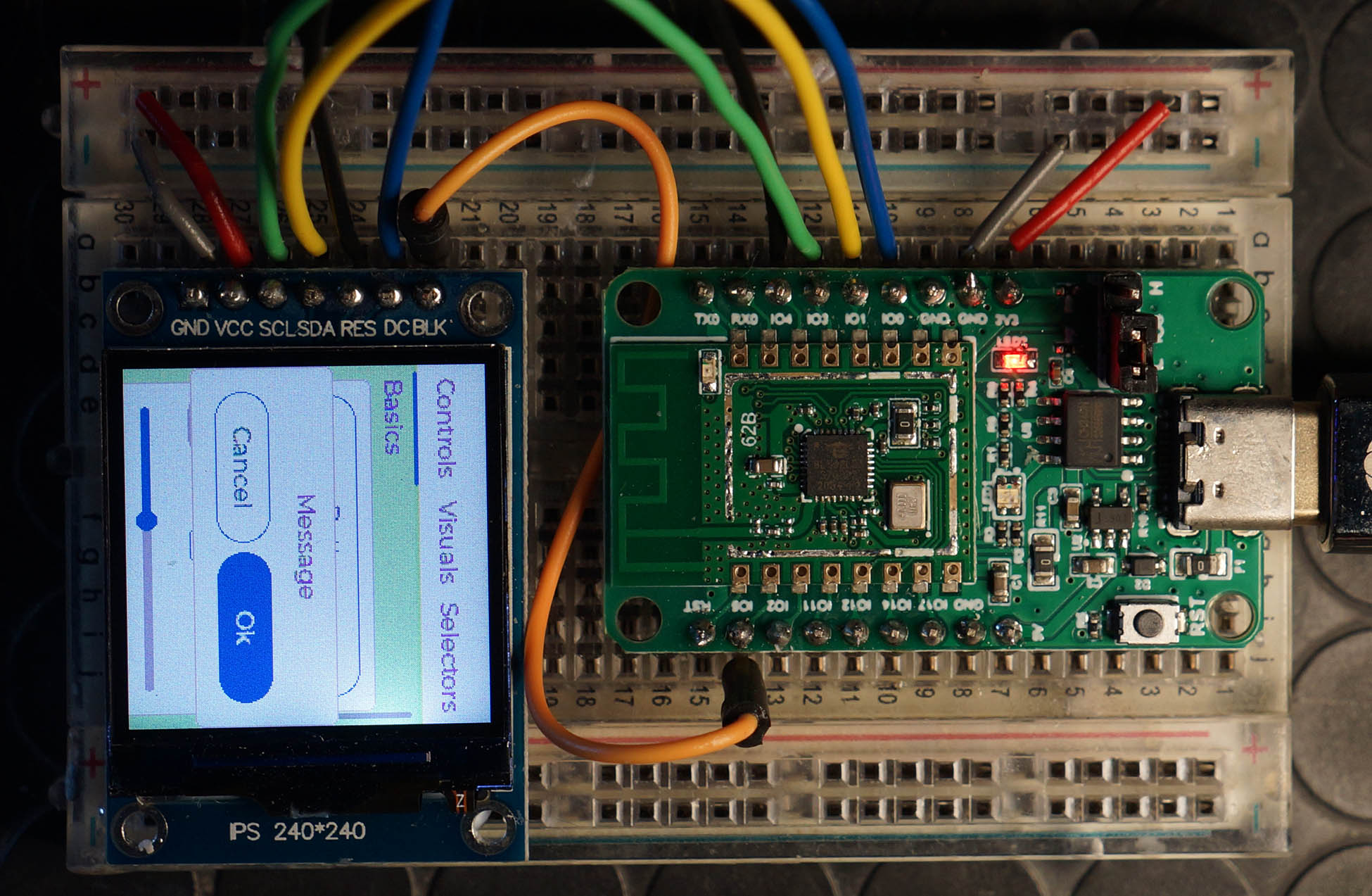
monitor_cb: 57600 px refreshed in 1100 msThe LVGL Demo Screen appears on ST7789 yay! (Colours in the display below are inverted, should be red instead of blue)
How do we render UI controls with the LVGL Library?
We render UI controls by creating LVGL Widgets.
Here’s how the LVGL Demo App renders the screen above: lv_demo_widgets.c
//  Create Demo Widgets
void lv_demo_widgets(void) {
  //  Create a Tab View Widget
  tv = lv_tabview_create(lv_scr_act(), NULL);
  ...
  //  Create 3 tabs: Controls, Visuals, Selectors
  t1 = lv_tabview_add_tab(tv, "Controls");
  t2 = lv_tabview_add_tab(tv, "Visuals");
  t3 = lv_tabview_add_tab(tv, "Selectors");
  ...
  //  Create the widgets for the Controls, Visuals and Selectors Tabs
  controls_create(t1);
  visuals_create(t2);
  selectors_create(t3);
}
The Demo Screen looks overcrowded for a tiny display, but we can make out 3 tabs: “Controls”, “Visuals” and “Selectors”.
The app renders the 3 tabs by creating a Tab View Widget.
controls_create populates the Controls Tab with a Message Box Widget (and other widgets) like so: lv_demo_widgets.c
//  Create widgets for the Controls Tab
static void controls_create(lv_obj_t * parent) {
  ...
  //  Create a Message Box Widget
  lv_obj_t * m = lv_msgbox_create(lv_scr_act(), NULL);

  //  Define the Message Box Buttons
  static const char * btns[] = {"Cancel", "Ok", ""};

  //  Add the buttons to the Message Box
  lv_msgbox_add_btns(m, btns);
Check out the LVGL Docs to get started on writing our own LVGL App…
LVGL gets updated frequently (every few months). Can we set the LVGL Version in NuttX?
Yes we can specify the LVGL Version in menuconfig…
After setting the LVGL Version, be sure to delete all downloaded versions of LVGL before building NuttX…
## TODO: Change this to the path of our "nuttx" folder
cd nuttx/nuttx

## Preserve the Build Config
cp .config ../config

## Erase the build files
make clean

## Erase the Build Config and Kconfig files
make distclean

## For BL602: Configure the build for BL602
./tools/configure.sh bl602evb:nsh

## For PineDio Stack BL604: Configure the build for BL604
./tools/configure.sh bl602evb:pinedio

## For ESP32: Configure the build for ESP32.
## TODO: Change "esp32-devkitc" to our ESP32 board.
./tools/configure.sh esp32-devkitc:nsh

## Restore the Build Config
cp ../config .config

## Erase all downloaded versions of LVGL
rm ../apps/graphics/lvgl/v7*.zip
rm ../apps/graphics/lvgl/v8*.zip

## Build NuttX
make
NuttX is currently bundled with LVGL Version 7.3.0.
But the latest version of LVGL is 8.2.0.
And LVGL 8 is not backward compatible with LVGL 7. These are the breaking changes…
What happens if we switch to LVGL 8.2.0?
NuttX Build fails when downloading the Demo Code for LVGL 8.2.0…
make[3]: Entering directory '/home/user/nuttx/apps/examples/lvgldemo'
Downloading: v8.2.0.zip
Unpacking: v8.2.0.zip -> lv_demos
Archive:  v8.2.0.zip
  End-of-central-directory signature not found.  Either this file is not
  a zipfile, or it constitutes one disk of a multi-part archive.  In the
  latter case the central directory and zipfile comment will be found on
  the last disk(s) of this archive.
unzip:  cannot find zipfile directory in one of v8.2.0.zip or
        v8.2.0.zip.zip, and cannot find v8.2.0.zip.ZIP, period.
It seems the NuttX Build needs to be fixed to support LVGL 8.
LVGL 7.11.0 is the last version of LVGL 7. What happens if we switch to LVGL 7.11.0?
NuttX Build fails when we switch to LVGL 7.11.0…
nuttx/apps/graphics/lvgl/lv_conf.h:86:50: error: incompatible types when initializing type 'short unsigned int' using type 'lv_color_t' {aka 'union <anonymous>'}
 #define LV_COLOR_TRANSP    ((lv_color_t){.full = (CONFIG_LV_COLOR_TRANSP)})
                                                  ^
nuttx/apps/graphics/lvgl/lvgl/src/lv_core/../lv_draw/lv_img_buf.h:351:25: note: in expansion of macro 'LV_COLOR_TRANSP'
         lv_color_t ct = LV_COLOR_TRANSP;
We might need to identify the latest version of LVGL 7 that works with NuttX.
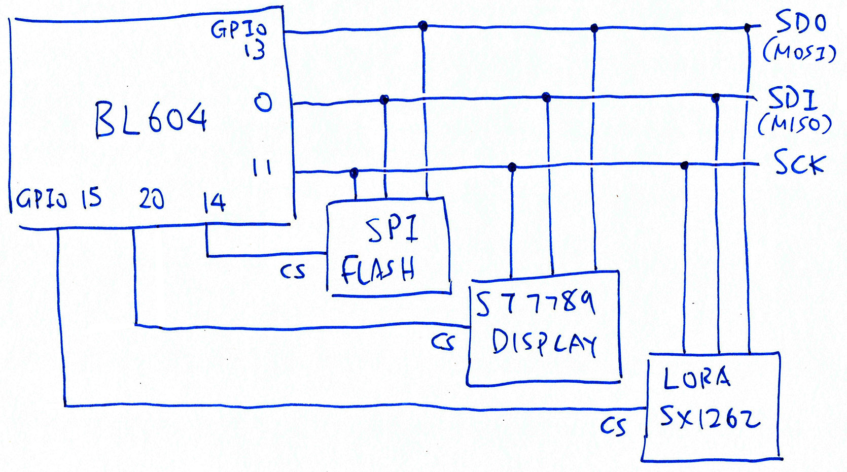
Do we expect any problems with ST7789 in complex IoT Gadgets?
Possibly. The pic above shows that PineDio Stack BL604 connects ST7789 to the same SPI Bus as SPI Flash and Semtech SX1262 LoRa Transceiver.
To prevent crosstalk on the SPI Bus, we need to flip the Chip Select Pin (CS) for each SPI Device.
Will the ST7789 Driver play nice with multiple SPI Devices sharing the same SPI Bus?
Not yet. The BL602 SPI Driver in NuttX assumes that the Chip Select Pin is controlled by BL602’s SPI Port (in hardware): bl602_spi.c
//  Select the SPI Device by flipping the
//  Chip Select Pin from High to Low
static void bl602_spi_select(struct spi_dev_s *dev, uint32_t devid, bool selected) {
  //  Nothing here, we use BL602's
  //  Hardware Chip Select
We might change this to flip the Chip Select Pin ourselves.
(devid will identify the SPI Device)
UPDATE: We have implemented the Shared SPI Bus for PineDio Stack. (See this)
Can’t we flip the Chip Select Pin inside the ST7789 Driver? (Instead of SPI Driver)
Nope we can’t flip the Chip Select Pin inside the ST7789 Driver. That’s because the ST7789 Driver / SPI Flash Driver / SX1262 Driver will call this to lock the SPI Bus: bl602_spi.c
//  Lock the BL602 SPI Bus
static int bl602_spi_lock(struct spi_dev_s *dev, bool lock) {
  ...
  //  Lock with a NuttX Semaphore
  if (lock) {
    ret = nxsem_wait_uninterruptible(&priv->exclsem);
  } else {
    ret = nxsem_post(&priv->exclsem);
  }
…Before calling bl602_spi_select to select the SPI Device.
So we need to flip the Chip Select Pin inside bl602_spi_select.
ST7789 receives plenty of data on the SPI Bus (for screen updates). Will there be contention?
Most definitely. That’s why we need to implement SPI DMA on BL602 so that our gadget can do other tasks while painting the ST7789 Display.
(Right now the BL602 SPI Driver polls the SPI Port when transferring SPI data)
UPDATE: SPI DMA is now supported on BL602 NuttX…
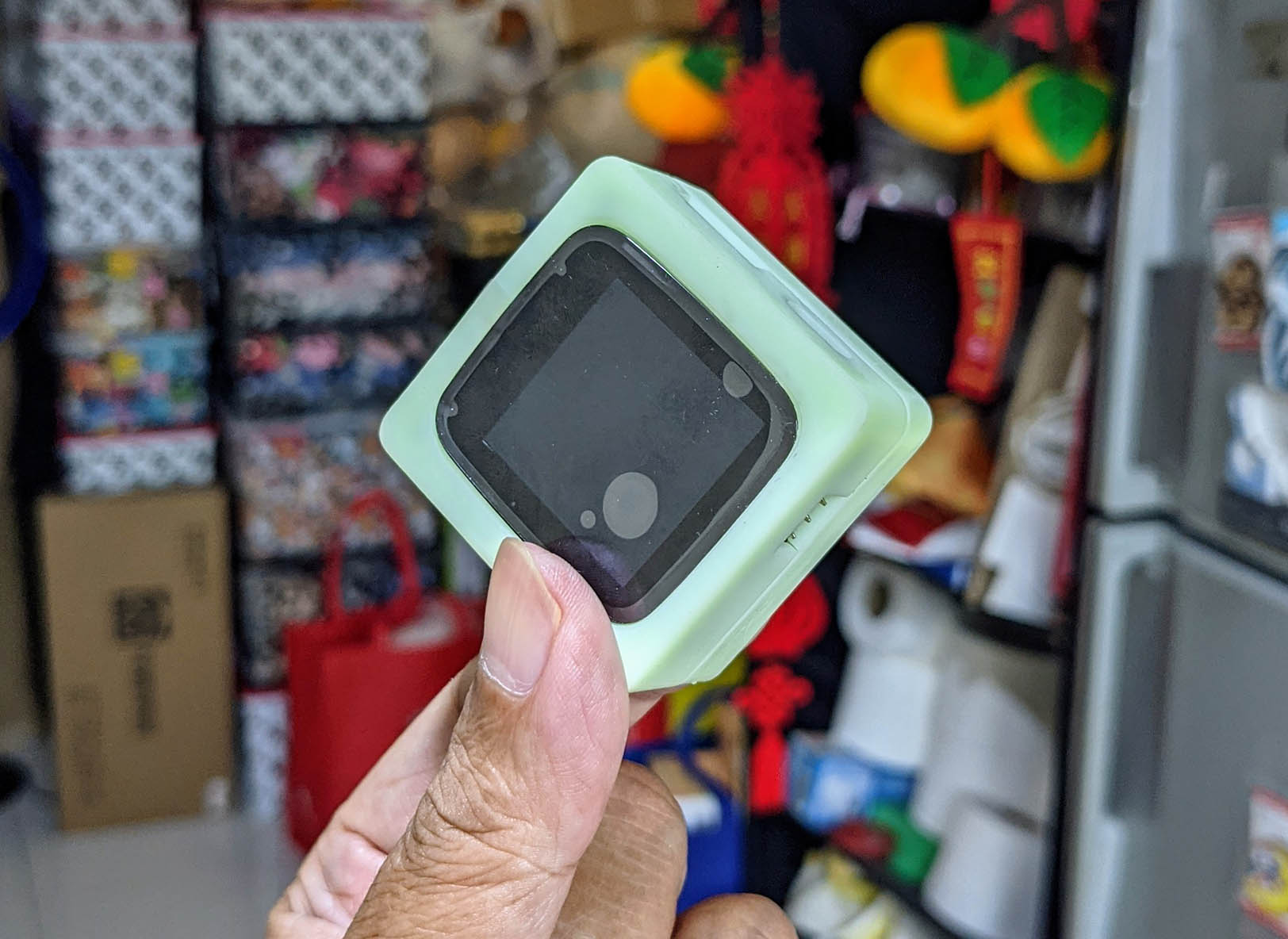
Pine64 PineDio Stack BL604
In the next article we’ll run NuttX with ST7789 Driver and LVGL Library on a real IoT gadget: Pine64’s PineDio Stack BL604!
Many Thanks to my GitHub Sponsors for supporting my work! This article wouldn’t have been possible without your support.
Got a question, comment or suggestion? Create an Issue or submit a Pull Request here…
lupyuen.github.io/src/st7789.md
This article is the expanded version of this Twitter Thread
There are recent changes to the ST7789 Driver that may affect SPI DMA performance…
This section explains how we implemented the ST7789 Data / Command Pin on BL602 NuttX…
To control the Data / Command Pin on ST7789 SPI Display, the SPI Driver flips the MISO Pin as though it was a GPIO. Here’s the existing implementation for ESP32-C3: esp32c3_board_spi.c
#if defined(CONFIG_ESP32C3_SPI2) && defined(CONFIG_SPI_CMDDATA)

int esp32c3_spi2_cmddata(FAR struct spi_dev_s *dev, uint32_t devid, bool cmd)
{
#if defined(CONFIG_LCD_ST7735) || defined(CONFIG_LCD_ST7789) || \
    defined(CONFIG_LCD_GC9A01)
  if (devid == SPIDEV_DISPLAY(0))
    {
      /*  This is the Data/Command control pad which determines whether the
       *  data bits are data or a command.
       */

      esp32c3_gpiowrite(CONFIG_ESP32C3_SPI2_MISOPIN, !cmd);

      return OK;
    }

#endif
  spiinfo("devid: %" PRIu32 " CMD: %s\n", devid, cmd ? "command" :
          "data");

  return -ENODEV;
}

#endif
To implement this on BL602, we reconfigure MISO from SPI Pin to GPIO Pin on the fly: bl602_spi.c
#ifdef CONFIG_SPI_CMDDATA
static int bl602_spi_cmddata(struct spi_dev_s *dev,
                              uint32_t devid, bool cmd)
{
  spiinfo("devid: %" PRIu32 " CMD: %s\n", devid, cmd ? "command" :
          "data");

#if defined(CONFIG_LCD_ST7735) || defined(CONFIG_LCD_ST7789) || \
    defined(CONFIG_LCD_GC9A01)
  if (devid == SPIDEV_DISPLAY(0))
    {
      gpio_pinset_t gpio;
      int ret;

      /* reconfigure MISO from SPI Pin to GPIO Pin */

      gpio = (BOARD_SPI_MISO & GPIO_PIN_MASK)
            | GPIO_OUTPUT | GPIO_PULLUP | GPIO_FUNC_SWGPIO;
      ret = bl602_configgpio(gpio);
      if (ret < 0)
        {
          spierr("Failed to configure MISO as GPIO\n");
          DEBUGPANIC();

          return ret;
        }

      /* set MISO to high (data) or low (command) */

      bl602_gpiowrite(gpio, !cmd);

      return OK;
    }
#endif

  spierr("SPI cmddata not supported\n");
  DEBUGPANIC();

  return -ENODEV;
}
#endif
Note that BOARD_SPI_MISO & GPIO_PIN_MASK preserves the MISO GPIO Number when reconfiguring from SPI Pin to GPIO Pin.
When the SPI Port is deselected (after the SPI operation), we revert MISO back from GPIO Pin to SPI Pin: bl602_spi.c
static void bl602_spi_select(struct spi_dev_s *dev, uint32_t devid, bool selected) {
  ...
#ifdef CONFIG_SPI_CMDDATA
  /* revert MISO from GPIO Pin to SPI Pin */

  if (!selected)
    {
      bl602_configgpio(BOARD_SPI_MISO);
    }
#endif
}
We must revert because the SPI Bus may be shared by other SPI Drivers. (Like the Semtech SX1262 Driver on PineDio Stack BL604)
We tested this implementation of SPI Cmd/Data with NuttX ST7789 Driver and a Logic Analyser on PineCone BL602. Logic Analyser shows that MISO goes Low when transmitting ST7789 Commands…
And MISO goes High when transmitting ST7789 Data…
We also tested LVGL with ST7789 on PineCone BL602:
As for regular SPI Devices that don’t require SPI Cmd/Data, we tested CONFIG_SPI_CMDDATA=y with Semtech SX1262 SPI Transceiver on PineCone BL602:
(Our implementation of SPI Cmd/Data has been merged into NuttX)
This section explains how we fixed SPI Send on BL602 NuttX…
On BL602, SPI Poll Send bl602_spi_poll_send() doesn’t send any data because it doesn’t enable SPI Master and it doesn’t clear the SPI FIFO.
SPI Poll Send also hangs because it loops forever waiting for the SPI FIFO: bl602_spi.c
static uint32_t bl602_spi_poll_send(struct bl602_spi_priv_s *priv, uint32_t wd)
{
  uint32_t val;
  uint32_t tmp_val = 0;

  /* write data to tx fifo */

  putreg32(wd, BL602_SPI_FIFO_WDATA);

  /* This loop hangs because SPI Master is not enabled and SPI FIFO is not cleared */

  while (0 == tmp_val)
    {
      /* get data from rx fifo */

      tmp_val = getreg32(BL602_SPI_FIFO_CFG_1);
      tmp_val = (tmp_val & SPI_FIFO_CFG_1_RX_CNT_MASK)
                >> SPI_FIFO_CFG_1_RX_CNT_SHIFT;
    }
This problem affects the NuttX ST7789 Driver because the ST7789 Driver calls SPI Poll Send via SPI_SEND() and bl602_spi_send().
We fix this problem by moving the code that enables SPI Master and clears the FIFO, from SPI Poll Exchange bl602_spi_poll_exchange() to SPI Poll Send. (Note that SPI Poll Exchange calls SPI Poll Send)
Before fixing, SPI Poll Send looks like this: bl602_spi.c
static uint32_t bl602_spi_poll_send(struct bl602_spi_priv_s *priv, uint32_t wd)
{
  uint32_t val;
  uint32_t tmp_val = 0;

  /* write data to tx fifo */

  putreg32(wd, BL602_SPI_FIFO_WDATA);

  while (0 == tmp_val)
    {
      /* get data from rx fifo */
      ...
After fixing, SPI Poll Send enables SPI Master and clears SPI FIFO: bl602_spi.c
static uint32_t bl602_spi_poll_send(struct bl602_spi_priv_s *priv, uint32_t wd)
{
  uint32_t val;
  uint32_t tmp_val = 0;

  /* spi enable master */

  modifyreg32(BL602_SPI_CFG, SPI_CFG_CR_S_EN, SPI_CFG_CR_M_EN);

  /* spi fifo clear  */

  modifyreg32(BL602_SPI_FIFO_CFG_0, SPI_FIFO_CFG_0_RX_CLR
              | SPI_FIFO_CFG_0_TX_CLR, 0);

  /* write data to tx fifo */

  putreg32(wd, BL602_SPI_FIFO_WDATA);

  while (0 == tmp_val)
    {
      /* get data from rx fifo */
      ...
Logic Analyser shows that SPI Poll Send now transmits SPI Data correctly:
Note that the MOSI Pin shows the correct data. Before fixing, the data was missing.
As for the modified SPI Poll Exchange, we tested it with Semtech SX1262 SPI Transceiver on PineCone BL602: release-2022-03-28
(Our fix for SPI Poll Send has been merged into NuttX)
(For BL602, BL604 and ESP32)
Below are the steps to build, flash and run NuttX on BL602, BL604 and ESP32.
The instructions below will work on Linux (Ubuntu), WSL (Ubuntu) and macOS.
(Instructions for other platforms)
Now we configure our NuttX project…
Install the build prerequisites…
Assume that we have downloaded the NuttX Source Code (or patched an existing NuttX Project)…
Configure the build…
cd nuttx

## For BL602: Configure the build for BL602
./tools/configure.sh bl602evb:nsh

## For PineDio Stack BL604: Configure the build for BL604
./tools/configure.sh bl602evb:pinedio

## For ESP32: Configure the build for ESP32.
## TODO: Change "esp32-devkitc" to our ESP32 board.
./tools/configure.sh esp32-devkitc:nsh

## Edit the Build Config
make menuconfig
Enable SPI Port…
In menuconfig, select “System Type”
For BL602: Check the box for “BL602 Peripheral Support” → “SPI0”
For ESP32: Check the box for “ESP32 Peripheral Select” → “SPI 2”
Hit “Exit” until the Top Menu appears. (“NuttX/x64_64 Configuration”)
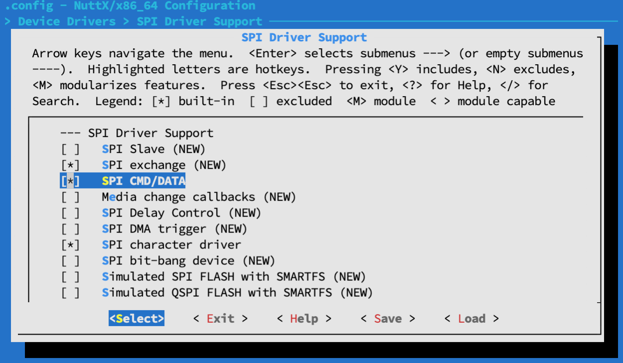
Enable SPI Cmd/Data…
Select “Device Drivers” → “SPI Driver”
Check the boxes for the following…
SPI Exchange
SPI CMD/DATA
SPI Character Driver
Hit “Exit” until the Top Menu appears. (“NuttX/x64_64 Configuration”)
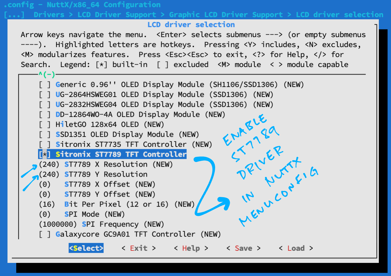
Enable ST7789 Driver…
Select “Device Drivers” → “LCD Driver Support” → “Graphic LCD Driver Support” → “LCD Driver Selection”
Check the box for “Sitronix ST7789 TFT Controller”
Assuming our ST7789 Display has 240 x 240 resolution…
For “X Resolution”: Set to 240
For “Y Resolution”: Set to 240
For “SPI Mode”: Check your ST7789 Display
(For BL602: We hardcode to SPI Mode 3)
Hit “Exit” until the Top Menu appears. (“NuttX/x64_64 Configuration”)
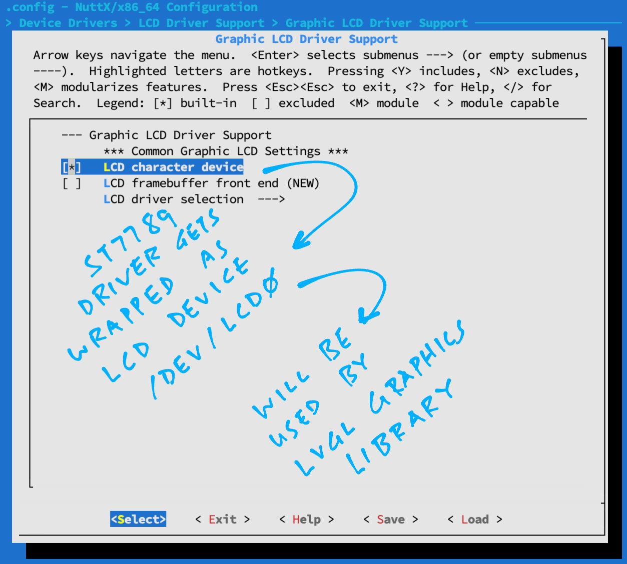
Enable LCD Character Device…
Select “Device Drivers” → “LCD Driver Support” → “Graphic LCD Driver Support LCD” → “Character Device”
Hit “Exit” until the Top Menu appears. (“NuttX/x64_64 Configuration”)
The ST7789 Display will be connected to NuttX at “/dev/lcd0”
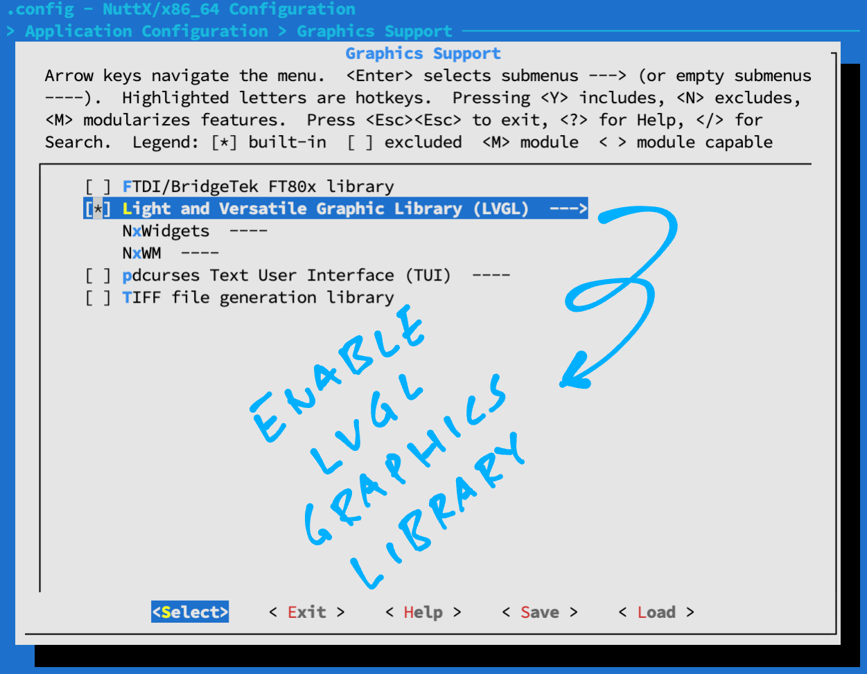
Enable LVGL Library…
Select “Application Configuration” → “Graphics Support”
Check the box for “Light and Versatile Graphic Library (LVGL)”
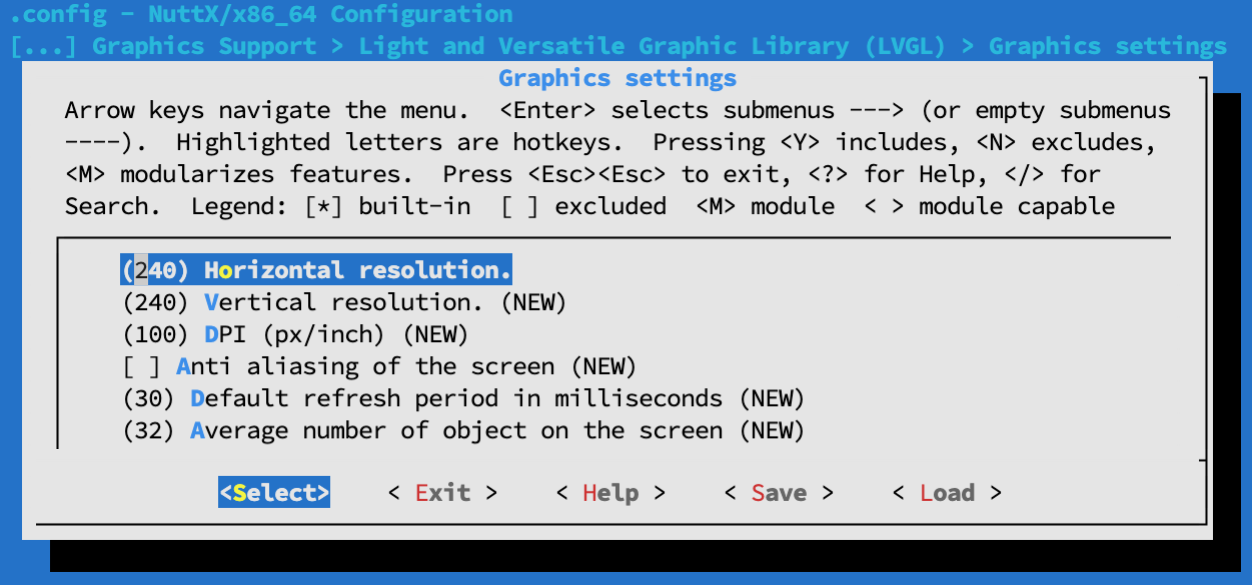
Select “Light and Versatile Graphic Library (LVGL)” → “Graphics Settings”
Assuming our ST7789 Display has 240 x 240 resolution…
For “Horizontal Resolution”: Set to 240
For “Vertical Resolution”: Set to 240
Hit “Exit”
Select “Color settings”
Check the box for “Swap the 2 bytes of RGB565 color”
Hit “Exit” until the Top Menu appears. (“NuttX/x64_64 Configuration”)
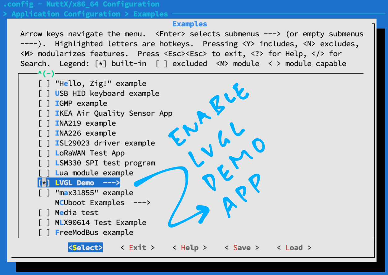
Enable LVGL Demo App…
Select “Application Configuration” → “Examples” → “LVGL Demo”
Hit “Exit” until the Top Menu appears. (“NuttX/x64_64 Configuration”)
Enable ls command…
Select “Application Configuration” → “NSH Library” → “Disable Individual commands”
Uncheck “Disable ls”
Hit “Exit” until the Top Menu appears. (“NuttX/x64_64 Configuration”)
Enable Logging and Assertion Checks…
Select “Build Setup” → “Debug Options”
Check the boxes for the following…
Enable Debug Features
Enable Error Output
Enable Warnings Output
Enable Informational Debug Output
Enable Debug Assertions
GPIO Debug Features
GPIO Error Output
GPIO Warnings Output
GPIO Informational Output
SPI Debug Features
SPI Error Output
SPI Warnings Output
Graphics Debug Features
Graphics Error Output
Graphics Warnings Output
Graphics Informational Output
Low-level LCD Debug Features
LCD Driver Error Output
LCD Driver Warnings Output
LCD Driver Informational Output
Hit “Exit” until the Top Menu appears. (“NuttX/x64_64 Configuration”)
Save the configuration and exit menuconfig
Follow these steps to build NuttX for BL602, BL604 or ESP32…
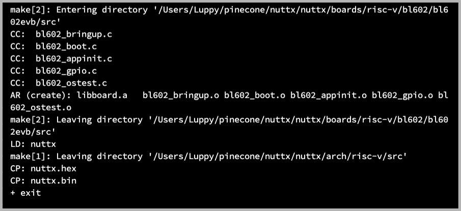
To build NuttX, enter this command…
makeWe should see…
LD: nuttx
CP: nuttx.hex
CP: nuttx.binFor WSL: Copy the NuttX Firmware to the c:\blflash directory in the Windows File System…
##  /mnt/c/blflash refers to c:\blflash in Windows
mkdir /mnt/c/blflash
cp nuttx.bin /mnt/c/blflash
For WSL we need to run blflash under plain old Windows CMD (not WSL) because it needs to access the COM port.
In case of problems, refer to the NuttX Docs…
For ESP32: See instructions here (Also check out this article)
For BL602 / BL604: Follow these steps to install blflash…
We assume that our Firmware Binary File nuttx.bin has been copied to the blflash folder.
Set BL602 / BL604 to Flashing Mode and restart the board…
For PineDio Stack BL604:
Set the GPIO 8 Jumper to High (Like this)
Disconnect the USB cable and reconnect
Or use the Improvised Reset Button (Here’s how)
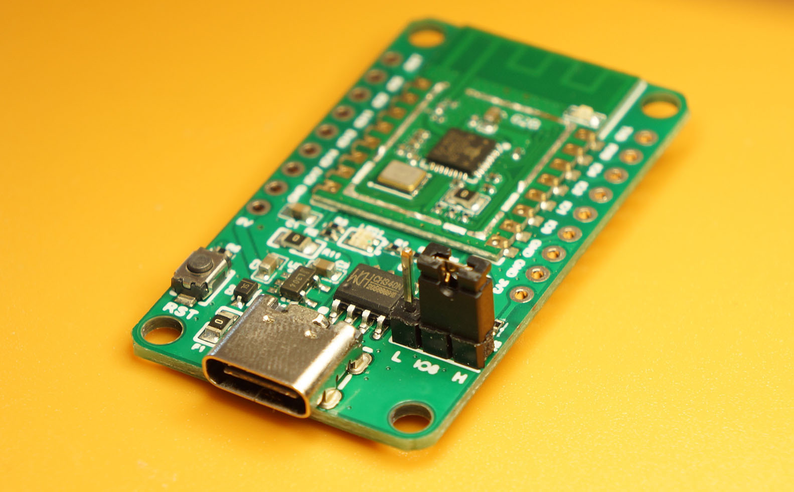
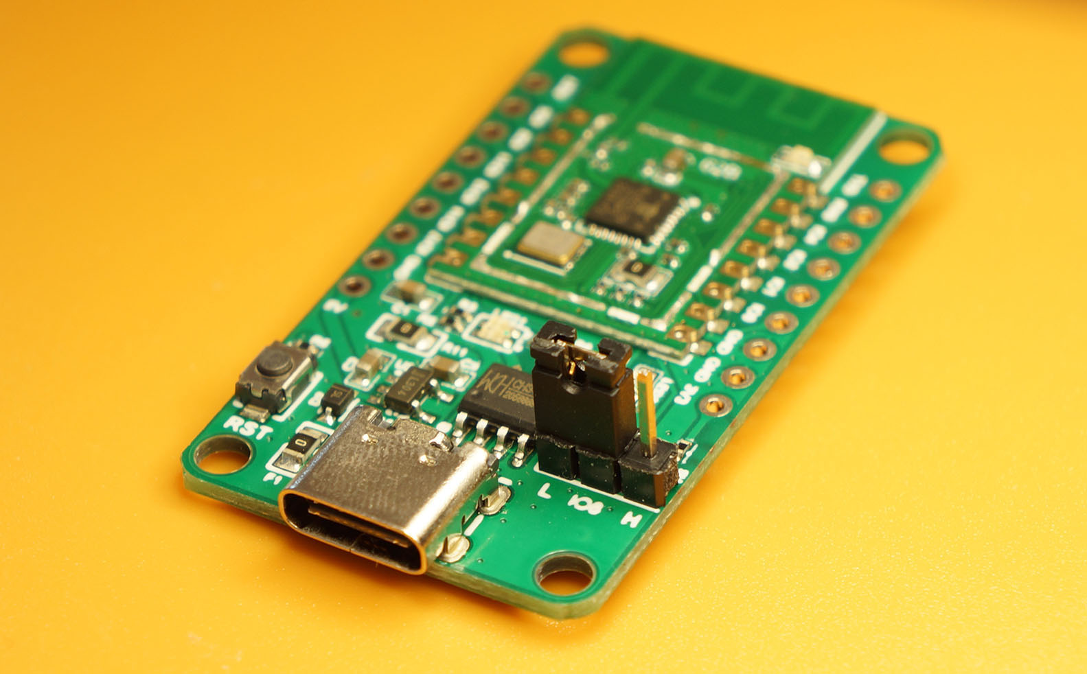
For PineCone BL602:
Set the PineCone Jumper (IO 8) to the H Position (Like this)
Press the Reset Button
For BL10:
Connect BL10 to the USB port
Press and hold the D8 Button (GPIO 8)
Press and release the EN Button (Reset)
Release the D8 Button
For Ai-Thinker Ai-WB2, Pinenut and MagicHome BL602:
Disconnect the board from the USB Port
Connect GPIO 8 to 3.3V
Reconnect the board to the USB port
Enter these commands to flash nuttx.bin to BL602 / BL604 over UART…
## For Linux: Change "/dev/ttyUSB0" to the BL602 / BL604 Serial Port
blflash flash nuttx.bin \
--port /dev/ttyUSB0
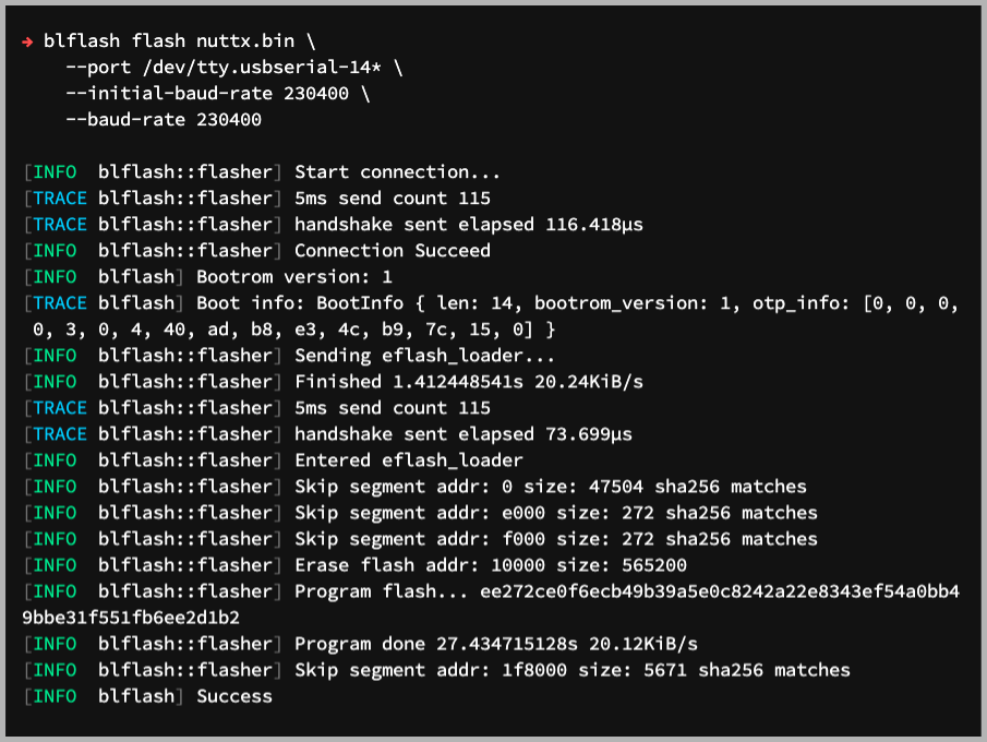
## For macOS: Change "/dev/tty.usbserial-1410" to the BL602 / BL604 Serial Port
blflash flash nuttx.bin \
--port /dev/tty.usbserial-1410 \
--initial-baud-rate 230400 \
--baud-rate 230400
## For Windows: Change "COM5" to the BL602 / BL604 Serial Port
blflash flash c:\blflash\nuttx.bin --port COM5For WSL: Do this under plain old Windows CMD (not WSL) because blflash needs to access the COM port.
(Flashing WiFi apps to BL602 / BL604? Remember to use bl_rfbin)
(More details on flashing firmware)
For ESP32: Use Picocom to connect to ESP32 over UART…
picocom -b 115200 /dev/ttyUSB0For BL602 / BL604: Set BL602 / BL604 to Normal Mode (Non-Flashing) and restart the board…
For PineDio Stack BL604:
Set the GPIO 8 Jumper to Low (Like this)
Disconnect the USB cable and reconnect
Or use the Improvised Reset Button (Here’s how)
For PineCone BL602:
Set the PineCone Jumper (IO 8) to the L Position (Like this)
Press the Reset Button
For BL10:
For Ai-Thinker Ai-WB2, Pinenut and MagicHome BL602:
Disconnect the board from the USB Port
Connect GPIO 8 to GND
Reconnect the board to the USB port
After restarting, connect to BL602 / BL604’s UART Port at 2 Mbps like so…
For Linux:
screen /dev/ttyUSB0 2000000For macOS: Use CoolTerm (See this)
For Windows: Use putty (See this)
Alternatively: Use the Web Serial Terminal (See this)
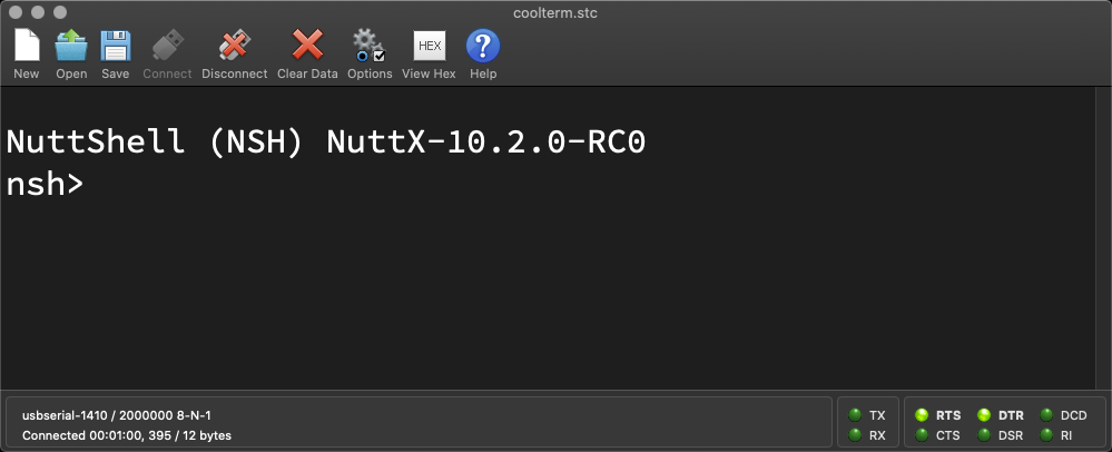
Press Enter to reveal the NuttX Shell…
NuttShell (NSH) NuttX-10.2.0-RC0
nsh>
Congratulations NuttX is now running on BL602 / BL604!
(More details on connecting to BL602 / BL604)
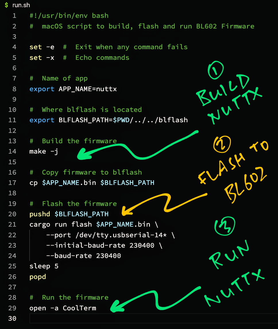
macOS Tip: Here’s the script I use to build, flash and run NuttX on macOS, all in a single step: run.sh
ST7789 SPI Display connected to Pine64 PineCone BL602 RISC-V Board