📝 24 Nov 2021
Tasty Nutty Treat on PineDio Stack BL604 RISC-V Board
Among all Embedded Operating Systems, Apache NuttX is truly unique because…
NuttX runs on 8-bit, 16-bit, 32-bit AND 64-bit microcontrollers…
Spanning popular platforms like RISC-V, Arm, ESP32, AVR, x86, …
NuttX is strictly compliant with POSIX.
Which means that NuttX Applications shall access the Microcontroller Hardware by calling open(), read(), write(), ioctl(), …
(Looks like Linux Lite!)
For BL602 and BL604: NuttX and FreeRTOS are the only operating systems supported on the RISC-V + WiFi + Bluetooth LE SoCs from Bouffalo Lab.
If you’re wondering: NuttX is named after its creator Gregory Nutt. And X because it’s POSIX Compliant.
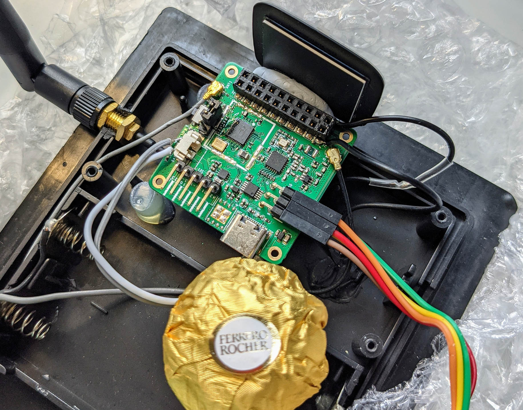
Today we shall build, flash and run NuttX on the PineCone BL602 and PineDio Stack BL604 RISC-V Boards. (Pic above)
(The steps in this NuttX tutorial / primer should work on any BL602 or BL604 Board: Ai-Thinker Ai-WB2, Pinenut, DT-BL10, MagicHome BL602, …)
We’ll briefly explore the internals of NuttX to understand how it works…
Coding a microcontroller with Linux-like (POSIX) functions might sound odd, but we’ll appreciate the benefits in a while.
(And we might have an interesting way to support Embedded Rust on NuttX!)
Follow the steps below to build, flash and run NuttX for BL602 and BL604…
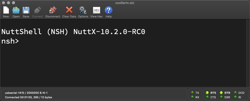
We should see the NuttX Shell on our Serial Terminal…
NuttShell (NSH) NuttX-10.2.0-RC0
nsh>
The default NuttX Firmware includes two Demo Apps…
Let’s test the Demo Apps.
In the NuttX Shell, enter…
helloWe should see…
Hello, World!!(Yep this is the plain and simple Hello World app!)
The Source Code looks very familiar: hello_main.c
#include <nuttx/config.h>
#include <stdio.h>

int main(int argc, FAR char *argv[])
{
  printf("Hello, World!!\n");
  return 0;
}
It looks exactly like on Linux! (Almost)
That’s because NuttX is POSIX Compliant. It supports Linux features like stdio, main() and printf().
Let’s run the Timer Demo App.
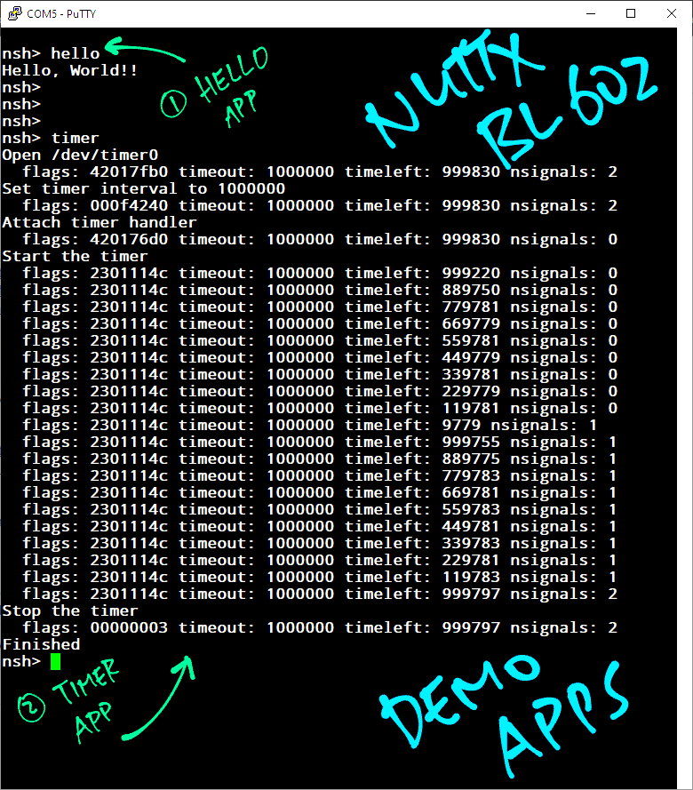
In the NuttX Shell, enter…
timerWe should see some Timeout Messages. (Pic above)
This Demo App accesses the System Timer in an interesting way: timer_main.c
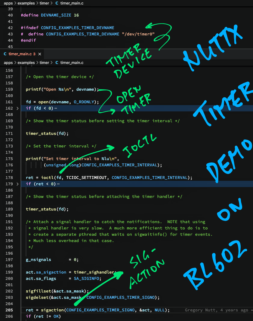
/dev/timer0 points to the System Timer
(Everything is a file… Just like Linux!)
We call open() to access the System Timer
ioctl() to set the Timeout
sigaction() to register the Timeout Handler
open(), ioctl() and sigaction() are common functions called by Linux Apps.
NuttX Apps really look like Linux Apps!
Let’s get adventurous and add NuttX Commands…
“help” to show the commands available
“ls” to list the devices in /dev
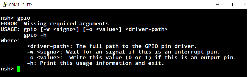
“gpio” to toggle the GPIO Output and flip an LED on/off
(See pic above)
Enter this command to configure the NuttX build on our computer…
make menuconfigLet’s explore the options.
(More about configuring NuttX)
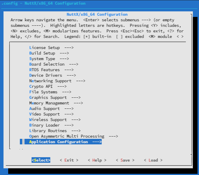
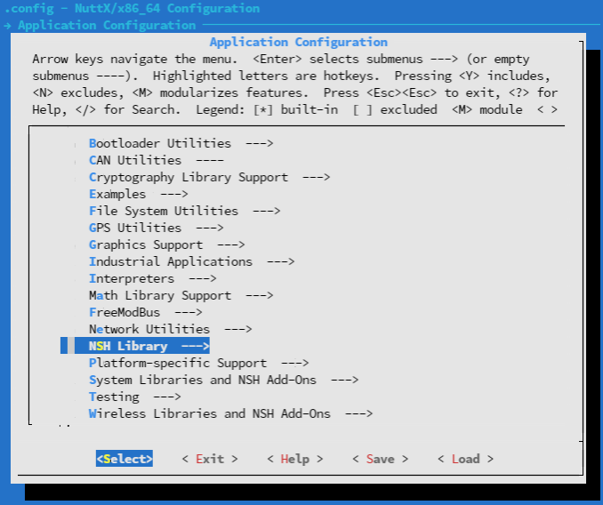
In menuconfig, select “Application Configuration”. (Pic above)
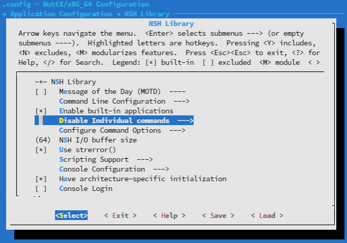
Select “NSH Library”…
Select “Disable Individual Commands”…
Uncheck the boxes for “help” and “ls”…
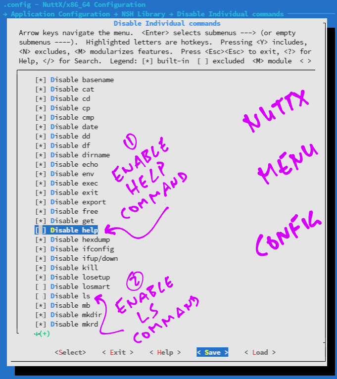
“help” and “ls” are now enabled in NuttX Shell!
Hit “Exit” until the Top Menu appears. (“NuttX/x64_64 Configuration”)
Select “Device Drivers”….
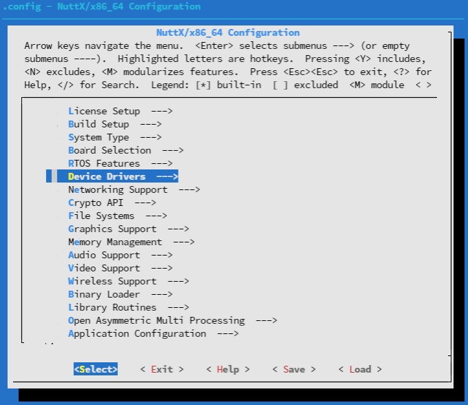
Select “IO Expander / GPIO Support”…
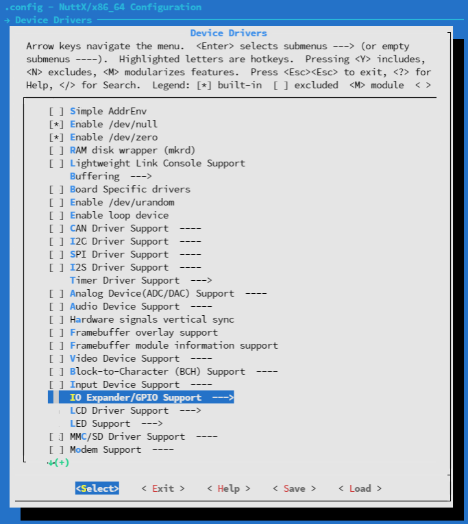
Check the box for “GPIO Driver”…
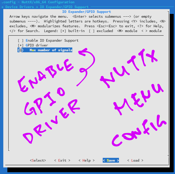
This enables the GPIO Driver for NuttX.
(If we don’t enable the GPIO Driver, NuttX won’t let us select the GPIO Demo App!)
Hit “Exit” until the Top Menu appears. (“NuttX/x64_64 Configuration”)
Select “Application Configuration”…
Select “Examples”…
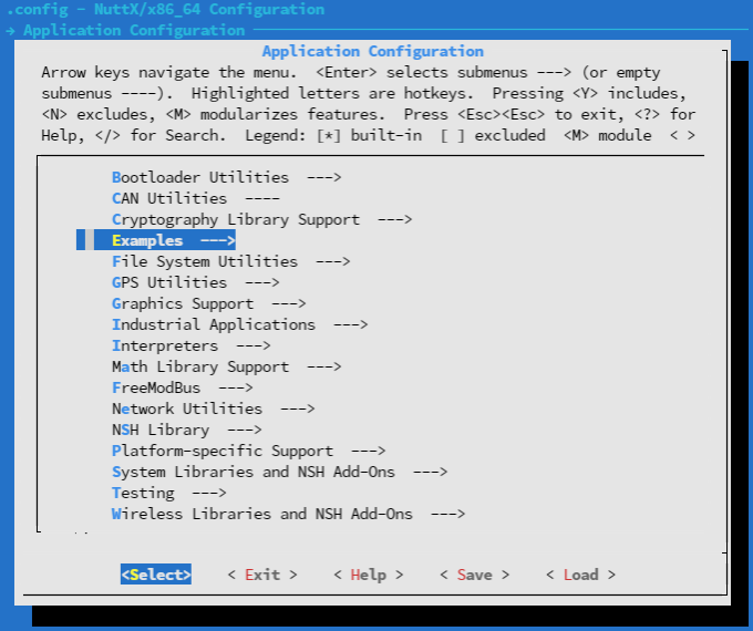
NuttX reveals the list of Demo Apps…
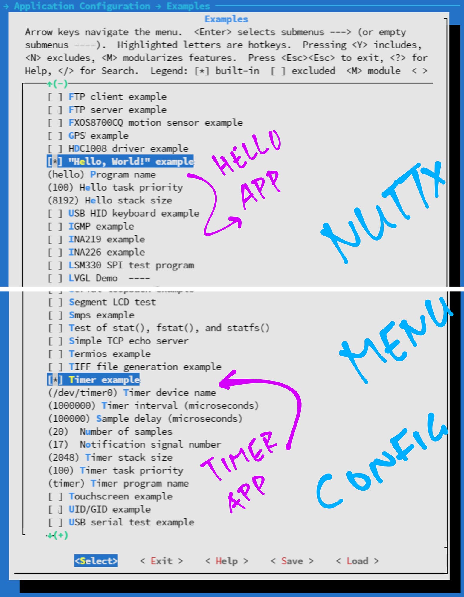
(Hello and Timer Demo Apps are already selected)
Check the box for “GPIO Driver Example”…

Hit “Save”…
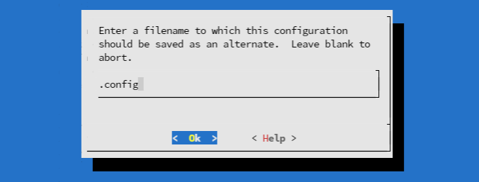
Then “OK” to save the NuttX Configuration to “.config”.
Hit “Exit” until menuconfig quits.
Whoa NuttX menuconfig looks amazing! But isn’t it a Linux thing?
NuttX happens to use the same menuconfig (Kconfig) tools as Linux.
Menuconfig generates a C Header File that contains the #define options. This header file is included for the NuttX Firmware Build.
(Zephyr is another RTOS that uses menuconfig and Kconfig)
Rebuild and copy the NuttX Firmware…
##  Rebuild NuttX
make

##  For WSL: Copy the firmware to /mnt/c/blflash, which refers to c:\blflash
mkdir /mnt/c/blflash
cp nuttx.bin /mnt/c/blflash
Flash and run the NuttX Firmware with these steps…
We’re ready to test the new commands!
Let’s run the new commands: “help”, “ls” and “gpio”.
In the NuttX Shell, enter…
help(“?” works too)
NuttX says that the “ls” and “gpio” commands are now available…
help usage: help [-v] [<cmd>]
  ?  help  ls  uname
Builtin Apps:
timer sh getprime hello nsh gpioRemember everything is a file in NuttX?
Let’s list the Hardware Devices in NuttX…
ls /devNuttX reveals the devices that we may control…
/dev:
 console
 gpio0
 gpio2
 gpio1
 null
 timer0
 zero
/dev/console is the Serial (UART) Console
/dev/gpio0 reads from GPIO Input
(Because we enabled the GPIO Driver)
/dev/gpio1 writes to GPIO Output
(But which GPIO Pin? We’ll learn in a while)
/dev/gpio2 captures the GPIO Interrupt
/dev/null is the Null Device
/dev/timer0 is the System Timer
(We’ve seen this earlier)
/dev/zero is the Null Source
Let’s write to the GPIO Output at /dev/gpio1.
Enter this to set the GPIO Output to High…
gpio -o 1 /dev/gpio1(As explained in the pic above)
The GPIO Output changes from Low to High…
Driver: /dev/gpio1
  Output pin:    Value=0
  Writing:       Value=1
  Verify:        Value=1
Can we do this to flip an LED on and off?
Not yet. We haven’t told NuttX which GPIO Pin our LED is connected to!
Let’s learn how.
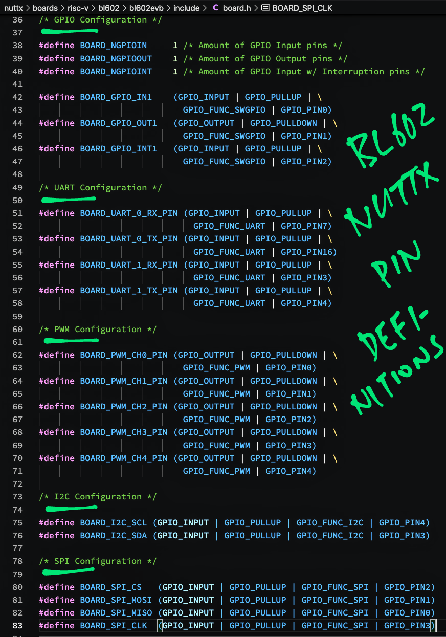
How do we define the Pin Numbers for GPIO, UART, PWM, I2C, SPI, …?
We define the Pin Numbers in board.h (Pic above)
Note: Some pins on BL602 and BL604 may only be assigned to specific functions.
More about pin selection…
How shall we define the GPIO Output Pin for our LED?
On PineCone BL602 the Blue LED is connected on GPIO 11.
We change the Pin Definition for BOARD_GPIO_OUT1 like so: board.h
//  GPIO Output Pin:
//  Changed GPIO_PIN1 to GPIO_PIN11 (Blue LED on PineCone BL602)
//  Changed GPIO_PULLDOWN to GPIO_FLOAT
#define BOARD_GPIO_OUT1 \
  (GPIO_OUTPUT | GPIO_FLOAT | \
    GPIO_FUNC_SWGPIO | GPIO_PIN11)

//  Previously:
//  #define BOARD_GPIO_OUT1 \
//    (GPIO_OUTPUT | GPIO_PULLDOWN | \
//      GPIO_FUNC_SWGPIO | GPIO_PIN1)
Make sure the Pin Number isn’t used by another port!
(FreeRTOS on BL602 uses a Device Tree to assign the pins)
Rebuild and copy the NuttX Firmware…
##  Rebuild NuttX
make

##  For WSL: Copy the firmware to /mnt/c/blflash, which refers to c:\blflash
mkdir /mnt/c/blflash
cp nuttx.bin /mnt/c/blflash
Flash and run the NuttX Firmware with these steps…
We’re ready to test the LED!
Let’s flip PineCone BL602’s LED on and off!
The Blue LED is wired to GPIO 11 like so…
Blue LED is On when GPIO 11 is Low
Blue LED is Off when GPIO 11 is High
At startup, the Blue LED is On (because the default GPIO Output is Low)…
In the NuttX Shell, enter this to flip GPIO 11 to High…
gpio -o 1 /dev/gpio1NuttX flips GPIO 11 from Low to High…
Driver: /dev/gpio1
  Output pin:    Value=0
  Writing:       Value=1
  Verify:        Value=1
Our Blue LED switches Off…
So far so good!
Enter this to flip GPIO 11 to Low…
gpio -o 0 /dev/gpio1As expected, NuttX flips GPIO 11 from High to Low…
Driver: /dev/gpio1
  Output pin:    Value=1
  Writing:       Value=0
  Verify:        Value=0
Our Blue LED switches On…
Congratulations we have successfully tested the BL602 LED with NuttX!
(Got problems with GPIO? See these troubleshooting tips)
(If we’re controlling LEDs, consider using NuttX’s LED Driver)
Let’s look inside NuttX to understand how the GPIO Driver works.
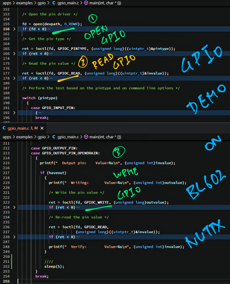
We start at the “gpio” command: gpio_main.c
From the pic above we see that the “gpio” command calls…
open(“/dev/gpio1”, …) to access the GPIO Pin
ioctl(…, GPIOC_READ, …) to read the GPIO Pin
ioctl(…, GPIOC_WRITE, …) to write to the GPIO Pin
What are GPIOC_READ and GPIOC_WRITE?
GPIOC_READ and GPIOC_WRITE are GPIO Driver Commands defined in the NuttX GPIO Interface…
The “gpio” command works across all NuttX Platforms because it calls the common GPIO Interface.
Below is the implementation of the platform-independent GPIO Interface (ioctl): gpio.c
//  Standard character driver ioctl method
static int gpio_ioctl(FAR struct file *filep, int cmd, unsigned long arg)
{
  ...
  //  Handle each GPIO Driver Command...
  switch (cmd)
    {
      //  If we're setting the value of an output GPIO...
      case GPIOC_WRITE:
        ...
        //  Call the Board-Specific GPIO Driver
        ret = dev->gp_ops->go_write(
          dev,       //  GPIO Device
          (bool)arg  //  1 (High) or 0 (Low)
        );
This is a Character Device Driver that handles each GPIO Driver Command (like GPIOC_WRITE).
The driver calls the Board-Specific GPIO Driver to execute the command.
What’s a Board-Specific Driver?
PineCone BL602 and PineDio Stack BL604 are two Dev Boards based on BL602 / BL604.
Each Dev Board has hardware features that are specific to the board. Like LEDs connected on different GPIO Pins.
NuttX isolates these board differences by calling a Board-Specific Driver.
(We’re actually calling the Board-Specific Driver for BL602 EVB)
Here is our Board-Specific GPIO Driver: bl602_gpio.c
//  Board-Specific GPIO Driver: Set the value of an output GPIO
static int gpout_write(FAR struct gpio_dev_s *dev, bool value)
{
  //  Alias the GPIO Device as bl602xgpio
  FAR struct bl602_gpio_dev_s *bl602xgpio =
    (FAR struct bl602_gpio_dev_s *)dev;
  ...
  //  Call the BL602-Specific GPIO Driver
  bl602_gpiowrite(                  //  Set GPIO Output...
    g_gpiooutputs[bl602xgpio->id],  //  GPIO Pin Set
    value                           //  1 (High) or 0 (Low)
  );
g_gpiooutputs maps the GPIO Device (like “/dev/gpio1”) to a GPIO Pin Set, which contains the GPIO Pin Number.
(Which makes sense, because each board may map the Hardware Devices to different GPIO Pins)
The Board-Specific Driver calls the BL602-Specific GPIO Driver to set the GPIO Output, passing the GPIO Pin Set.
The BL602-Specific GPIO Driver manipulates the BL602 Hardware Registers to perform GPIO Functions.
(The driver is called by the Board-Specific Drivers for all BL602 boards)
Here’s how the BL602-Specific GPIO Driver sets the GPIO Output: bl602_gpio.c
//  BL602-Specific GPIO Driver: Set the value of an output GPIO
void bl602_gpiowrite(gpio_pinset_t pinset, bool value)
{
  //  Extract the GPIO Pin Number from Pin Set
  uint8_t pin = (pinset & GPIO_PIN_MASK) >> GPIO_PIN_SHIFT;

  //  If we're setting the GPIO to High...
  if (value)
    {
      //  Set the pin's bit in the GPIO Output Register
      modifyreg32(BL602_GPIO_CFGCTL32, 0, (1 << pin));
    }
  else
    {
      //  Clear the pin's bit in the GPIO Output Register
      modifyreg32(BL602_GPIO_CFGCTL32, (1 << pin), 0);
    }
}BL602_GPIO_CFGCTL32 is the Address of the GPIO Output Register: 0x40000188
This code looks similar to GLB_GPIO_Write from BL602 IoT SDK’s Standard Driver.
That’s because NuttX implements its own Hardware Abstraction Layer (HAL) for BL602.
(Which might have quirks different from the BL602 IoT SDK)
(Got problems with the GPIO Driver? See these troubleshooting tips)
Let’s try out a fun freebie for NuttX… BASIC Interpreter!
One of the best things about NuttX: It comes with many freebies… Like the BASIC Interpreter!
Let’s do some BASIC on BL602 NuttX…
Configure our NuttX Build…
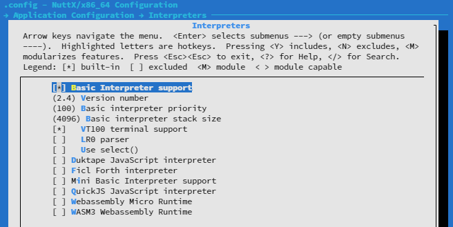
make menuconfigSelect “Application Configuration → Interpreters”
Check the box for “Basic Interpreter Support”
(Pic above)
Save the configuration and exit menuconfig
BL602 doesn’t support environment variables and folders, so we need to patch the source files…
“Disable environment variables and folders”
(See the modified files: bas_global.c and bas_statement.c)
We’ll use “peek” and “poke” in a while. Patch the source file to enable the commands…
Rebuild, reflash and rerun NuttX
In the NuttX Shell, enter…
basThe BASIC Interpreter comes to life!
bas 2.4
Copyright 1999-2014 Michael Haardt.
This is free software with ABSOLUTELY NO WARRANTY.
Go ahead and run a BASIC Program!
10 print "hello"
20 sleep 5
30 goto 10
list
run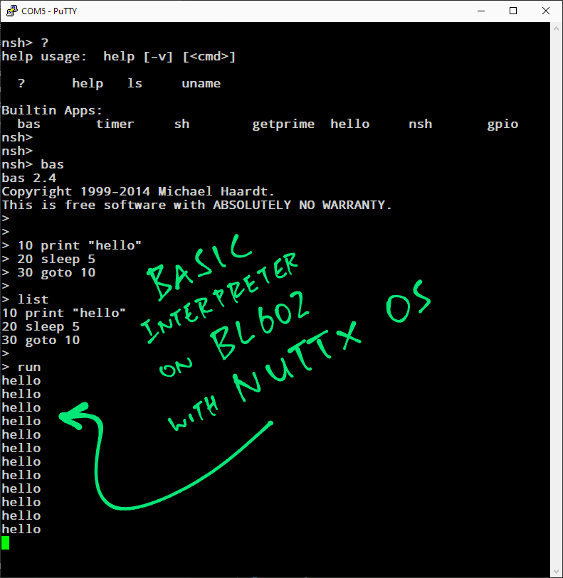
(Childhood Memories 🥲)
In the olden days we would “peek” and “poke” to light up pixels on our Apple ][… Let’s do the same for our BL602 LED!
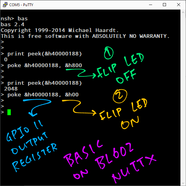
In the BASIC Interpreter, enter this…
print peek(&h40000188)
poke &h40000188, &h800
Remember that 0x40000188 is the Address of the GPIO Output Register.
Setting (or “poking”) this register to 0x800 will set GPIO 11 to High.
(Because 0x800 equals 1 << 11)
Which switches off the Blue LED on PineCone BL602.
Now do this…
print peek(&h40000188)
poke &h40000188, &h00
Setting the GPIO Output Register to 0x00 will set GPIO 11 to Low.
Which switches on the Blue LED.
For PineDio Stack BL604: Enter this to switch off the backlight…
print peek(&h40000188)
poke &h40000188, &h200000
And this to switch on the backlight…
print peek(&h40000188)
poke &h40000188, &h00
Yep it’s indeed possible to blink the LED in BASIC!
(OK this code isn’t so legit… We ought to preserve the existing bits in the register, not overwrite them)
Now that we understand NuttX inside out, let’s have a chat…
I’m familiar with Embedded Coding on Arduino / STM32 / nRF52 / BL602. NuttX’s POSIX Interface looks very strange to me: open(), read(), ioctl(), …
Well NuttX’s POSIX Interface might be a good thing for folks who are familiar with Linux and Single-Board Computers.
The NuttX Team has done an incredible job enforcing API Consistency across all kinds of platforms. “Write once run anywhere” might be true on NuttX!
In any case it’s hard to find an Open Source Embedded OS that supports so many platforms.
For BL602 and BL604, shall I use NuttX or FreeRTOS (BL602 IoT SDK)?
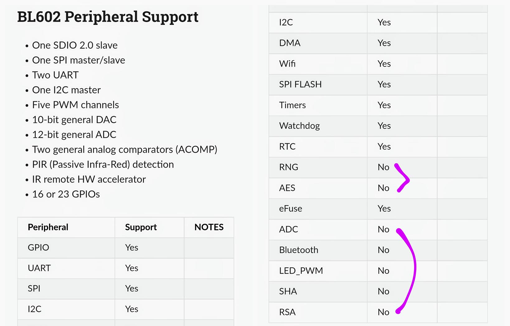
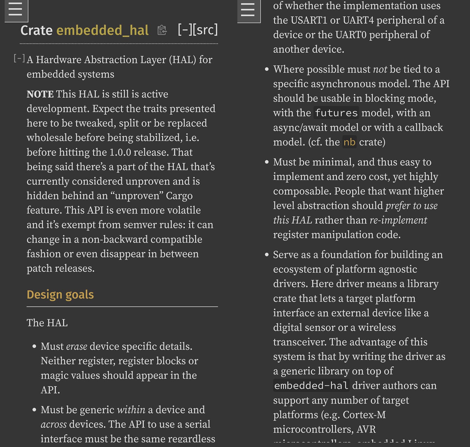
Remember that the NuttX Team (with Bouffalo Lab) has created their own Hardware Abstraction Layer (HAL) for BL602 / BL604. (See this)
Some features on BL602 / BL604 are not yet supported by NuttX. (Pic above)
But NuttX on BL602 is getting better every day!
(Though SPI with DMA is not yet supported on BL602 NuttX)
POSIX still looks kinda odd to me. Is there something we could do with Rust?
Thanks for asking! Yes we could wrap the POSIX Interface into a Rust Embedded HAL that’s familiar to many Rust coders.
And the Rust Embedded HAL might be portable across all NuttX platforms. Thanks to POSIX Compatibility!
More about this in the next section.
Does Rust provide a standard way to access the Hardware Functions on Microcontrollers?
Yes! The Embedded Rust Community has created a Hardware Abstraction Layer (HAL) that supports all kinds of Microcontrollers…
Take a look at these Hardware Interfaces in Rust Embedded HAL for…
How popular is the Rust Embedded HAL?
According to the official list…
37 Microcontrollers are supported by Rust Embedded HAL
64 Device Drivers have been built with Rust Embedded HAL
(Would be awesome if we could run all these Device Drivers on NuttX!)
So the Rust Embedded HAL is kinda like NuttX’s POSIX Interface?
Conceptually yes! Rust Embedded HAL was created to allow Rust Drivers and Apps to be portable across all Microcontroller Platforms.
Can we port Rust Embedded HAL to NuttX?
We could wrap the NuttX POSIX Interface into a Rust Embedded HAL.
This means that we build a layer of code that translates the Rust Embedded HAL Interface into the NuttX POSIX Interface.
And the Rust Embedded HAL for NuttX might be portable across all NuttX platforms. Thanks to POSIX Compatibility!
(Rust Embedded HAL might also become a friendlier API for NuttX)
Here’s how we ported Rust Embedded HAL to NuttX…
UPDATE: According to Brennan Ashton, Sony has worked on Rust for NuttX.
I’m new to NuttX but I had lots of fun experimenting with it. I hope you’ll enjoy NuttX too!
Here are some topics that I’ll explore in future articles…
PineDio Stack BL604: PineDio Stack is Pine64’s newest RISC-V board that comes with a Touchscreen and a LoRa SX1262 Transceiver…
SPI Driver: PineDio Stack BL604 has an onboard LoRa SX1262 Transceiver wired via SPI. Great way to test the NuttX SPI Driver for BL602 / BL604!
LoRaWAN Driver: Once we get SX1262 talking OK on SPI, we can port the LoRa and LoRaWAN Drivers to NuttX!
I2C: We’ll explore I2C on NuttX because it’s super useful for IoT Sensors and Touch Panels…
“Apache NuttX Driver for BME280 Sensor: Ported from Zephyr OS”
Graphics: NuttX works great with the ST7789 SPI Display and LVGL Graphics Libary, right out of the box…
Rust: I’m excited about porting the Rust Embedded HAL to NuttX. Here’s how we integrated NuttX GPIO, SPI and I2C with Rust…
Zig: Works on NuttX too…
IoT Sensors: NuttX is great for IoT devices! Here’s how we connect an Air Quality Sensor and encode Sensor Data efficiently with CBOR…
Automated Testing: This is how we do daily automated testing of NuttX on BL602 and BL604…
“(Mostly) Automated Testing of Apache NuttX RTOS on PineDio Stack BL604 RISC-V Board”
(BL602 IoT SDK / FreeRTOS is revamping right now to the new “hosal” HAL. Terrific time to explore NuttX now!)
Many Thanks to my GitHub Sponsors for supporting my work! This article wouldn’t have been possible without your support.
Got a question, comment or suggestion? Create an Issue or submit a Pull Request here…
lupyuen.github.io/src/nuttx.md
This article is the expanded version of this Twitter Thread
How do we use multiple Input / Output / Interrupt GPIOs on BL602? See this…
Having problems with NuttX? Check out the NuttX Mail Archive…
History of NuttX on BL602, how it all started…
More about NuttX on BL602…
For NuttX on RISC-V ESP32-C3…
“Installing Apache NuttX on Arch Linux for RISC-V and use it with RISC-V based ESP32-C3”
Xiaomi is actively contributing to NuttX…
“Xiaomi launches a new IoT Software Platform “Xiaomi Vela” based on NuttX OS”
The built-in “timer” Demo App we’ve seen uses Timer Handlers that are not deterministic and may have longer latency.
Check out the improved “timer_gpout” Demo App, which catches the Timer Signal in real time…
(Thanks to Sara Monteiro for the tip!)
Below are the steps to build, flash and run NuttX on BL602 and BL604.
The instructions below will work on Linux (Ubuntu), WSL (Ubuntu) and macOS.
(Instructions for other platforms)
First we install the build prerequisites…
Install the Build Tools…
##  For Linux and WSL:
sudo apt install \
  bison flex gettext texinfo libncurses5-dev libncursesw5-dev \
  gperf automake libtool pkg-config build-essential gperf genromfs \
  libgmp-dev libmpc-dev libmpfr-dev libisl-dev binutils-dev libelf-dev \
  libexpat-dev gcc-multilib g++-multilib picocom u-boot-tools util-linux \
  kconfig-frontends

##  For macOS:
brew install automake genromfs
##  Build "kconfig-frontends" because the "brew install" version doesn't work
pushd /tmp
git clone https://bitbucket.org/nuttx/tools.git
cd tools/kconfig-frontends
patch < ../kconfig-macos.diff -p 1
./configure --enable-mconf --disable-shared --enable-static --disable-gconf --disable-qconf --disable-nconf
##  Needed because "make" requires "aclocal-1.15" and "automake-1.15"
sudo ln -s /usr/local/bin/aclocal /usr/local/bin/aclocal-1.15
sudo ln -s /usr/local/bin/automake /usr/local/bin/automake-1.15
make
##  Install "kconfig-frontends"
make install
popd
(Instructions for Alpine Linux)
For PinePhone and 64-bit RISC-V: Skip this step
For BL602: Download the RISC-V GCC Toolchain from BL602 IoT SDK…
git clone https://github.com/lupyuen/bl_iot_sdkEdit ~/.bashrc (or equivalent) and add the BL602 toolchain to the PATH…
##  TODO: Change $HOME/bl_iot_sdk to the full path of bl_iot_sdk

##  For Linux and WSL:
PATH="$HOME/bl_iot_sdk/toolchain/riscv/Linux/bin:$PATH"

##  For macOS:
PATH="$HOME/bl_iot_sdk/toolchain/riscv/Darwin/bin:$PATH"
Update the PATH to enable the toolchain…
. ~/.bashrcFor ESP32: Instructions here
Next we download and build NuttX…
Download NuttX…
mkdir nuttx
cd nuttx
git clone --recursive https://github.com/lupyuen/nuttx nuttx
git clone --recursive https://github.com/lupyuen/nuttx-apps appsConfigure NuttX…
cd nuttx

## For BL602: Configure the build for BL602
./tools/configure.sh bl602evb:nsh

## For PineDio Stack BL604: Configure the build for BL604
./tools/configure.sh bl602evb:pinedio
We should see…
configuration written to .configIf we see this instead…
kconfig-tweak: command not foundCheck whether the kconfig-frontends package has been installed correctly. (See above)
Then delete the Build Configuration so that configure.sh can proceed…
make distclean

## For BL602: Configure the build for BL602
./tools/configure.sh bl602evb:nsh

## For PineDio Stack BL604: Configure the build for BL604
./tools/configure.sh bl602evb:pinedio
Build NuttX…
makeWe should see…
LD: nuttx
CP: nuttx.hex
CP: nuttx.binFor WSL: Copy the NuttX Firmware to the c:\blflash directory in the Windows File System…
##  /mnt/c/blflash refers to c:\blflash in Windows
mkdir /mnt/c/blflash
cp nuttx.bin /mnt/c/blflash
For WSL we need to run blflash under plain old Windows CMD (not WSL) because it needs to access the COM port.
In case of problems, refer to the NuttX Docs…
Follow these steps to install blflash…
We assume that our Firmware Binary File nuttx.bin has been copied to the blflash folder.
Set BL602 / BL604 to Flashing Mode and restart the board…
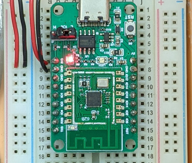
For PineDio Stack BL604:
Set the GPIO 8 Jumper to High (Like this)
Disconnect the USB cable and reconnect
Or use the Improvised Reset Button (Here’s how)
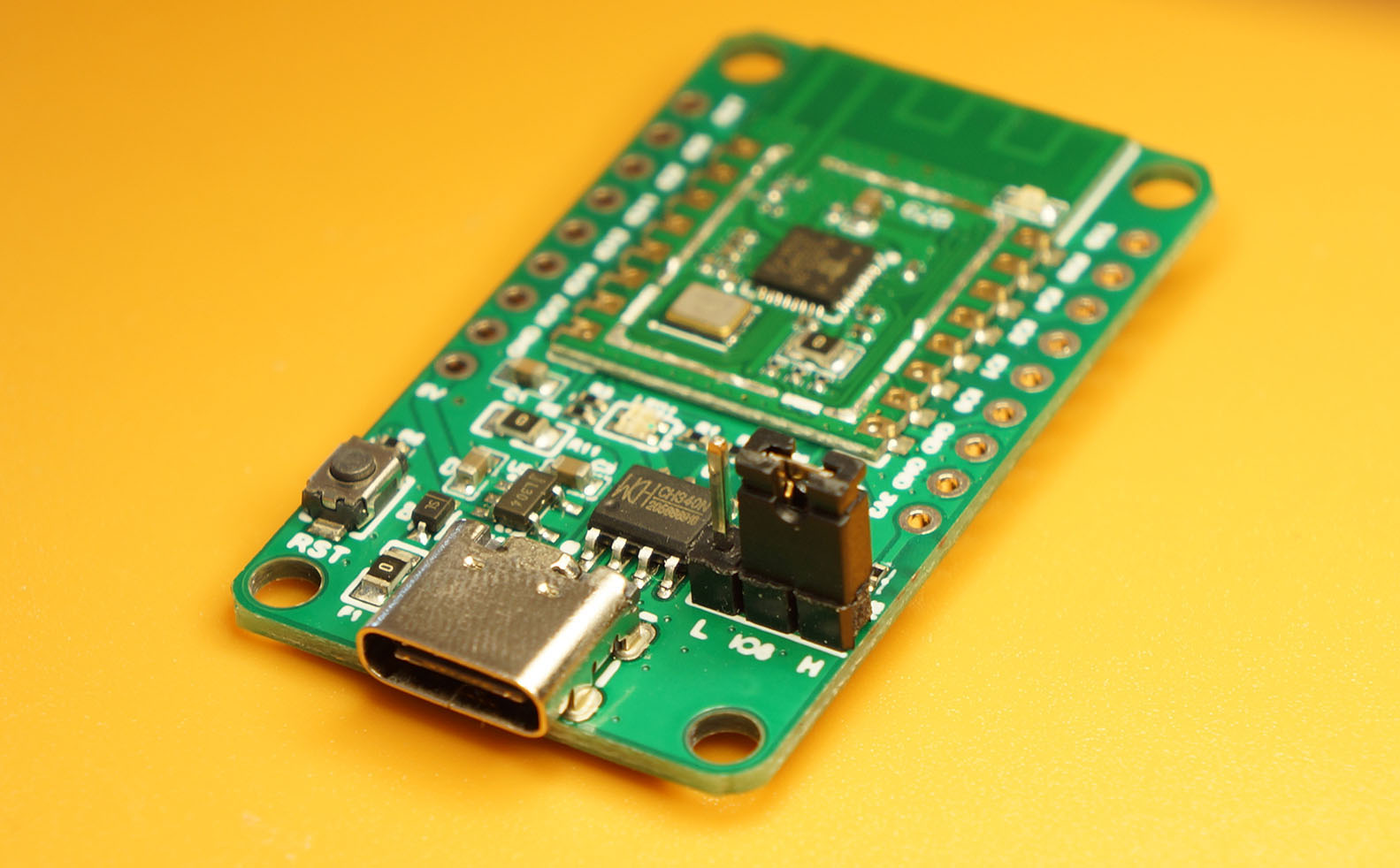
For PineCone BL602:
Set the PineCone Jumper (IO 8) to the H Position (Like this)
Press the Reset Button
For BL10:
Connect BL10 to the USB port
Press and hold the D8 Button (GPIO 8)
Press and release the EN Button (Reset)
Release the D8 Button
For Ai-Thinker Ai-WB2, Pinenut and MagicHome BL602:
Disconnect the board from the USB Port
Connect GPIO 8 to 3.3V
Reconnect the board to the USB port
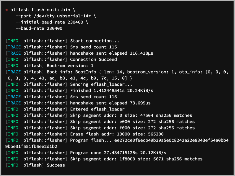
Enter these commands to flash nuttx.bin to BL602 / BL604 over UART…
## For Linux: Change "/dev/ttyUSB0" to the BL602 / BL604 Serial Port
blflash flash nuttx.bin \
  --port /dev/ttyUSB0

## For macOS: Change "/dev/tty.usbserial-1410" to the BL602 / BL604 Serial Port
blflash flash nuttx.bin \
  --port /dev/tty.usbserial-1410 \
  --initial-baud-rate 230400 \
  --baud-rate 230400

## For Windows: Change "COM5" to the BL602 / BL604 Serial Port
blflash flash c:\blflash\nuttx.bin --port COM5For WSL: Do this under plain old Windows CMD (not WSL) because blflash needs to access the COM port.
(Flashing WiFi apps to BL602 / BL604? Remember to use bl_rfbin)
(More details on flashing firmware)
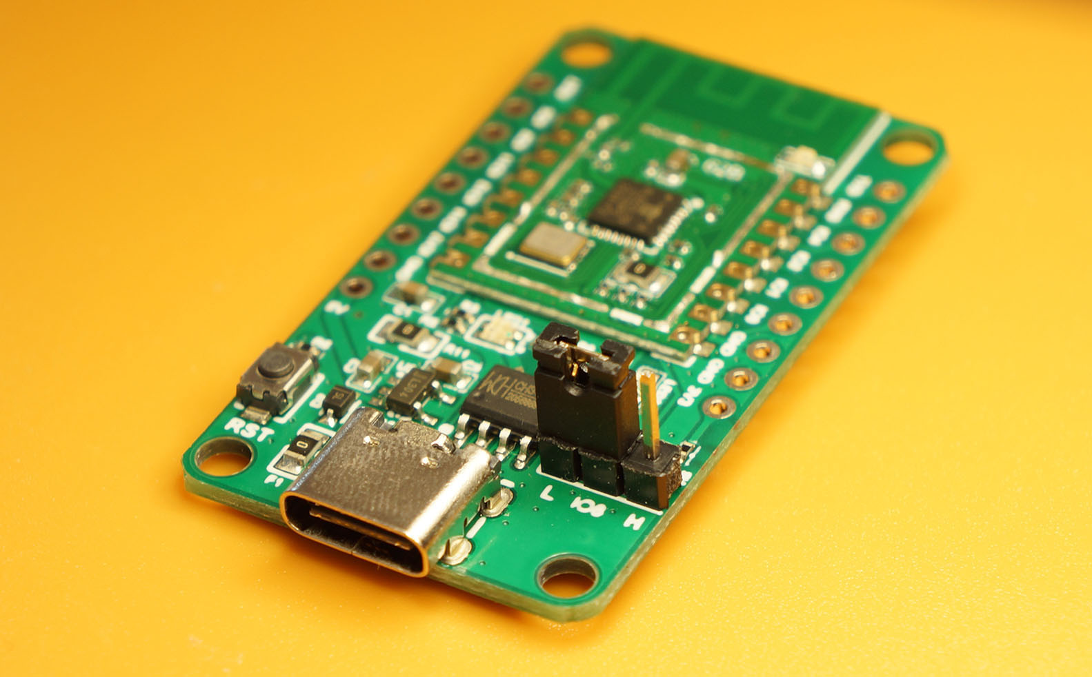
Set BL602 / BL604 to Normal Mode (Non-Flashing) and restart the board…
For PineDio Stack BL604:
Set the GPIO 8 Jumper to Low (Like this)
Disconnect the USB cable and reconnect
Or use the Improvised Reset Button (Here’s how)
For PineCone BL602:
Set the PineCone Jumper (IO 8) to the L Position (Like this)
Press the Reset Button
For BL10:
For Ai-Thinker Ai-WB2, Pinenut and MagicHome BL602:
Disconnect the board from the USB Port
Connect GPIO 8 to GND
Reconnect the board to the USB port
After restarting, connect to BL602 / BL604’s UART Port at 2 Mbps like so…
For Linux:
screen /dev/ttyUSB0 2000000For macOS: Use CoolTerm (See this)
For Windows: Use putty (See this)
Alternatively: Use the Web Serial Terminal (See this)
Press Enter to reveal the NuttX Shell…
NuttShell (NSH) NuttX-10.2.0-RC0
nsh>
Congratulations NuttX is now running on BL602 / BL604!
(More details on connecting to BL602 / BL604)
Here are the steps to enable NuttX Logging for easier troubleshooting…
Enter menuconfig…
make menuconfigSelect “Build Setup” → “Debug Options”
(Mandatory) Check the boxes for the following…
Enable Debug Features
Enable Error Output
Enable Warnings Output
Enable Debug Assertions

Graphics Debug Features
Graphics Error Output
Graphics Warnings Output

Low-level LCD Debug Features
LCD Driver Error Output
LCD Driver Warnings Output

Input Device Debug Features
Input Device Error Output
Input Device Warnings Output

GPIO Debug Features
GPIO Error Output
GPIO Warnings Output

I2C Debug Features
I2C Warnings Output
I2C Error Output

Sensor Debug Features
Sensor Warnings Output
Sensor Error Output

SPI Debug Features
SPI Error Output
SPI Warnings Output(Optional) To enable logging for the CST816S Touch Panel Driver, check the boxes for…
Enable Informational Debug Output
Input Device Informational Output
(Optional) To enable logging for ST7789 Display and LVGL Library, check the boxes for…
Enable Informational Debug Output
Graphics Informational Output
LCD Driver Informational Output
(Optional) To enable Logging for SX1262 LoRa Transceiver, check the box for…
Enable Informational Debug OutputAnd enable debugging for the SX1262 Library…
Library Routines → Semtech SX1262 Library → Logging → Debugging(Optional) To enable logging for I2C and Sensors, check the boxes for…
Enable Informational Debug Output
I2C Informational Output
Sensor Informational Output
(Optional) To enable logging for GPIO and SPI, check the boxes for…
Enable Informational Debug Output
GPIO Informational Output
SPI Informational Output
Note that “Enable Informational Debug Output” must be unchecked for the LoRaWAN Test App lorawan_test to work.
(Because LoRaWAN Timers are time-critical)
Save the configuration to .config and exit menuconfig
Rebuild NuttX…
makeFor WSL: Copy the NuttX Firmware to the c:\blflash directory in the Windows File System…
##  /mnt/c/blflash refers to c:\blflash in Windows
mkdir /mnt/c/blflash
cp nuttx.bin /mnt/c/blflashThis section describes the GPIO Output glitch that we observed in the BL602 GPIO Driver, and explains how we fixed it.
The fix has been merged into NuttX. (Thank you NuttX Maintainers! 🙏)
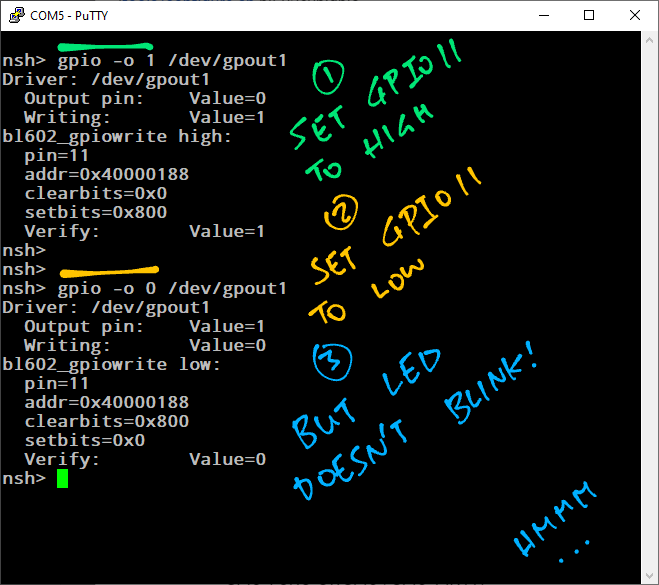
Summary of the GPIO Output glitch on BL602…
We have an LED connected to a GPIO Output Pin
Setting the GPIO Output to High and Low doesn’t blink the LED
We discover that the BL602 GPIO Driver doesn’t set the GPIO Output Enable Register
After patching the BL602 GPIO Driver to set the GPIO Output Enable Register, the LED blinks OK
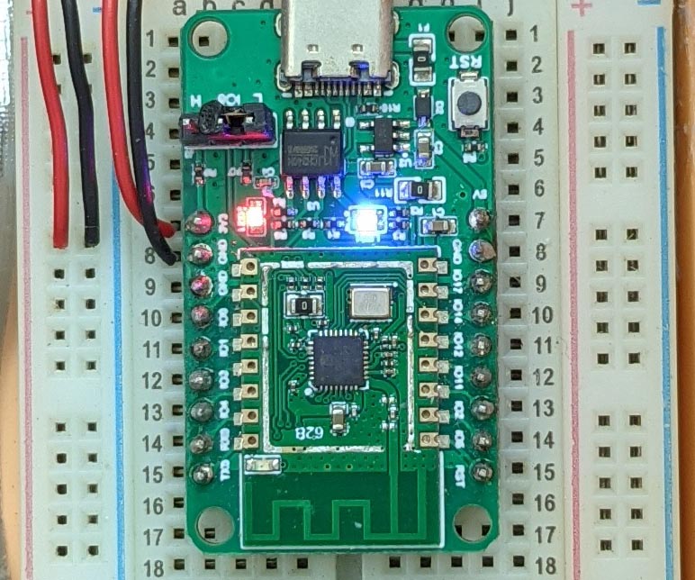
We observe the GPIO Output Glitch on Pine64 PineCone BL602 Board. (Pic above)
PineCone BL602 has a Blue LED connected on GPIO 11…
Blue LED is On when GPIO 11 is Low
Blue LED is Off when GPIO 11 is High
We configure GPIO 11 as the GPIO Output Pin BOARD_GPIO_OUT1 in board.h
//  GPIO Output Pin:
//  Changed GPIO_PIN1 to GPIO_PIN11 (Blue LED on PineCone BL602)
//  Changed GPIO_PULLDOWN to GPIO_FLOAT
#define BOARD_GPIO_OUT1 \
  (GPIO_OUTPUT | GPIO_FLOAT | \
    GPIO_FUNC_SWGPIO | GPIO_PIN11)

//  Previously:
//  #define BOARD_GPIO_OUT1 \
//    (GPIO_OUTPUT | GPIO_PULLDOWN | \
//      GPIO_FUNC_SWGPIO | GPIO_PIN1)
After building and flashing NuttX to BL602, we run the NuttX GPIO Command to toggle GPIO 11…
nsh> gpio -o 1 /dev/gpio1
Driver: /dev/gpio1
  Output pin:    Value=0
  Writing:       Value=1
  Verify:        Value=1

nsh> gpio -o 0 /dev/gpio1
Driver: /dev/gpio1
  Output pin:    Value=1
  Writing:       Value=0
  Verify:        Value=0
NuttX changes GPIO 11 from Low to High and back to Low.
But the BL602 LED doesn’t blink. Let’s track down the glitch.
To track down the glitch, we add debug logging to the BL602 GPIO Driver functions bl602_configgpio and bl602_gpiowrite…
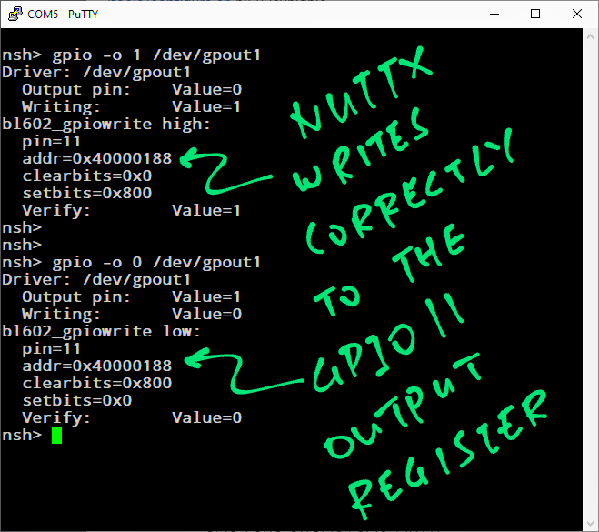
From the log we see that bl602_gpiowrite writes correctly to the GPIO Output Register at 0x40000188 (BL602_GPIO_CFGCTL32)…
bl602_gpiowrite high:
pin=11
addr=0x40000188
clearbits=0x0
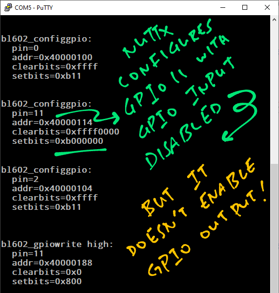
setbits=0x800At startup, bl602_configgpio configures GPIO 11 (0x40000114) with GPIO Input Disabled..
bl602_configgpio:
  pin=11
  addr=0x40000114
  clearbits=0xffff0000
  setbits=0xb000000
But bl602_configgpio doesn’t enable GPIO Output on GPIO 11.
According to the BL602 Reference Manual (Section 3.2.9 “GPIO Output”, Page 27), we should update the GPIO Output Enable Register to enable GPIO Output…
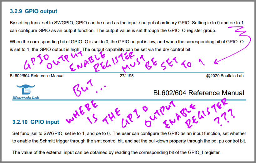
But the GPIO Output Enable Register is missing from the manual.
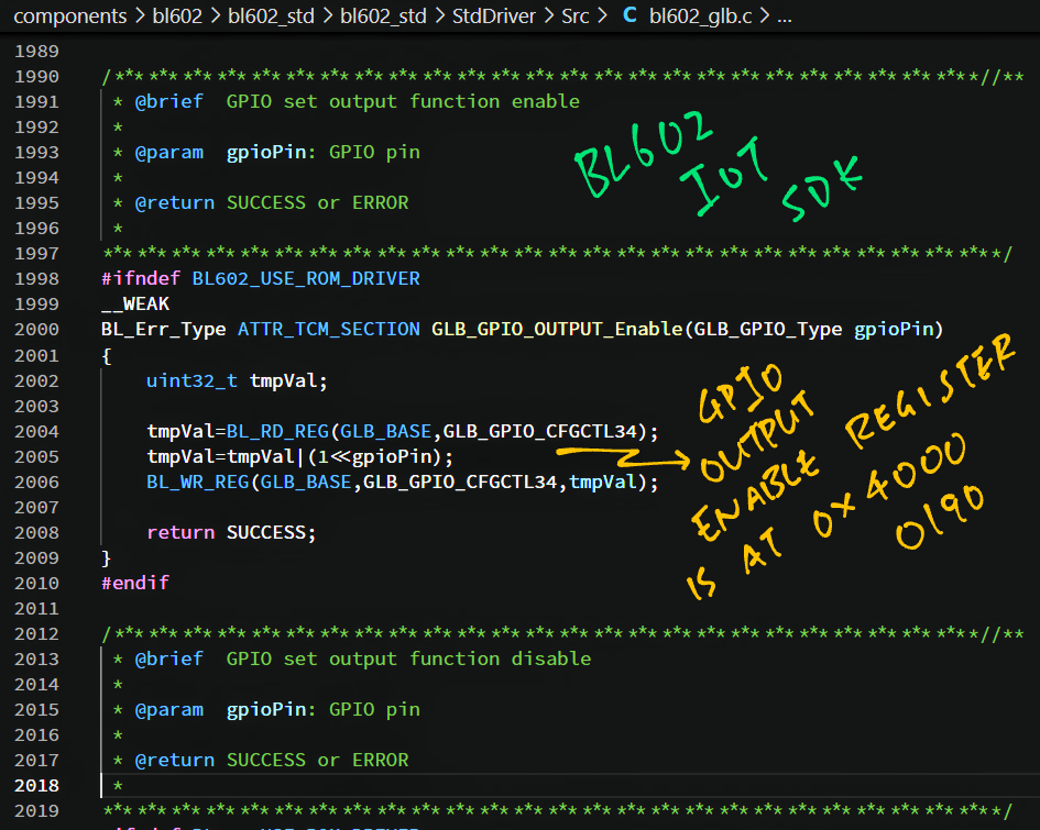
We look up BL602 IoT SDK and we discover in the function GLB_GPIO_OUTPUT_Enable that the GPIO Output Enable Register is at 0x40000190 (GLB_GPIO_CFGCTL34)…
Let’s update the GPIO Output Enable Register in NuttX.
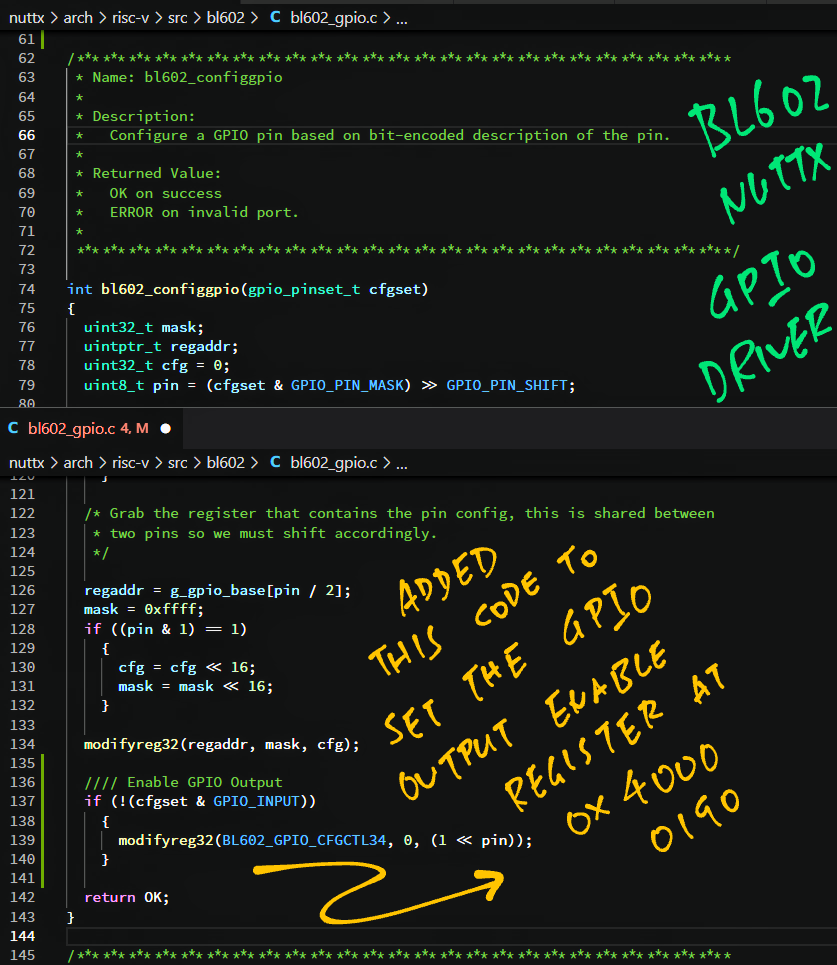
We patch the bl602_configgpio function to update the GPIO Output Enable Register: bl602_gpio.c
// Existing function
int bl602_configgpio(gpio_pinset_t cfgset)
{
  // Existing code
  ...
  modifyreg32(regaddr, mask, cfg);

  // Insert this code near the end of the function...
  // Enable GPIO Output if requested
  if (!(cfgset & GPIO_INPUT))
    {
      modifyreg32(            // Modify the register...
        BL602_GPIO_CFGCTL34,  // At address 0x40000190 (GPIO Enable Output)
        0,                    // Don't clear any bits
        (1 << pin)            // Set the bit for the GPIO Pin
      );
    }
  // End of inserted code

  // Existing code
  return OK;
}
Here is the patch…
Let’s test the patch.
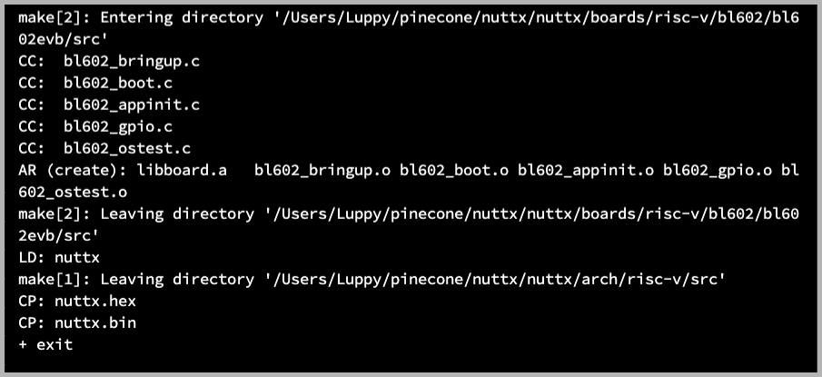
We rebuild and run the patched code.
At startup, the Blue LED is On (because the default GPIO Output is Low)…
(Remember the LED switches on when GPIO 11 is Low)
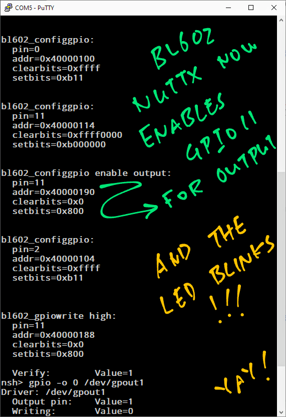
At startup the patched bl602_configgpio function correctly updates the GPIO Output Enable Register at 0x40000190…
bl602_configgpio enable output:
  pin=11
  addr=0x40000190
  clearbits=0x0
setbits=0x800We run the GPIO Command to set GPIO 11 to High…
nsh> gpio -o 1 /dev/gpio1
Driver: /dev/gpio1
  Output pin:    Value=0
  Writing:       Value=1
  Verify:        Value=1
PineCone’s Blue LED on GPIO 11 correctly switches off.
We run the GPIO Command to set GPIO 11 to Low…
nsh> gpio -o 0 /dev/gpio1
Driver: /dev/gpio1
  Output pin:    Value=1
  Writing:       Value=0
  Verify:        Value=0
And PineCone’s Blue LED on GPIO 11 correctly switches on.
We have successfully fixed the GPIO Output glitch!
The fix has been merged into NuttX…