📝 12 Feb 2022
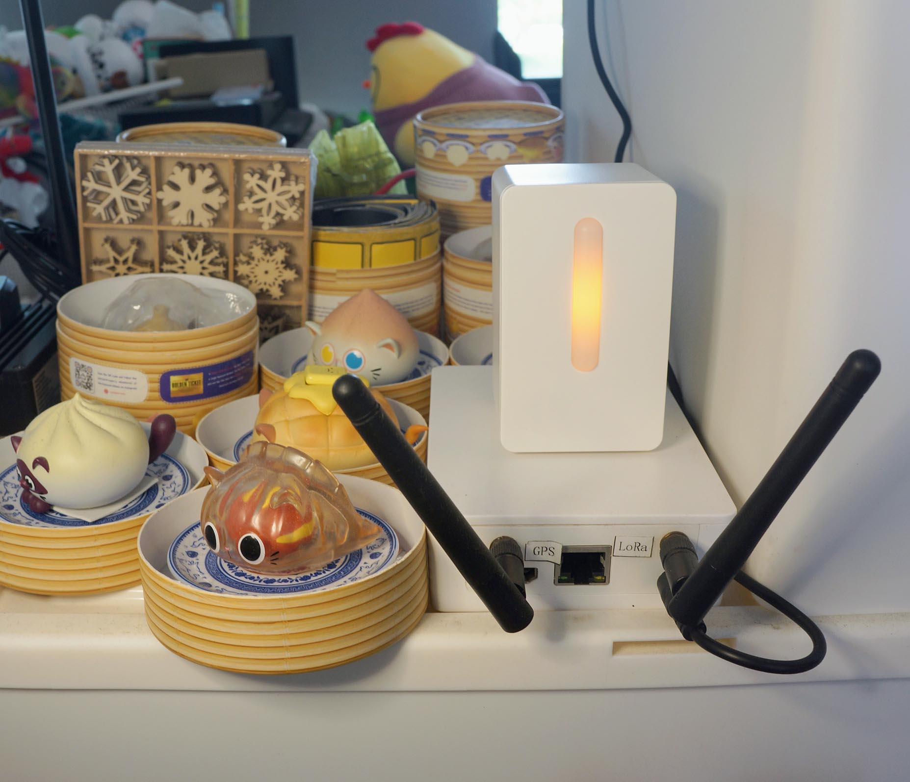
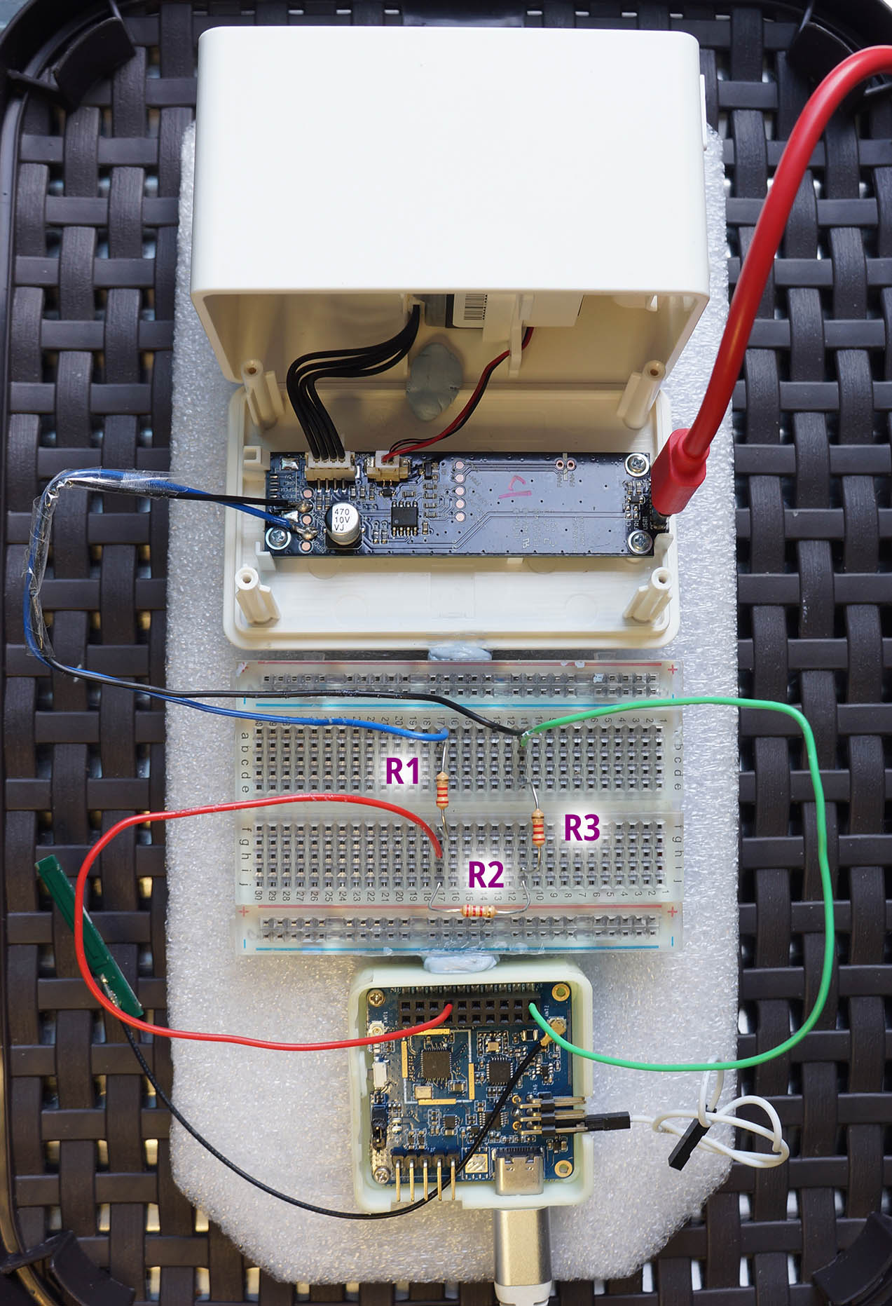
IKEA VINDRIKTNING Air Quality Sensor seated on Pine64 PineDio LoRa Gateway
IKEA VINDRIKTNING is a $12 hackable Air Quality Sensor that measures PM 2.5 (Particulate Matter) with reasonable accuracy.
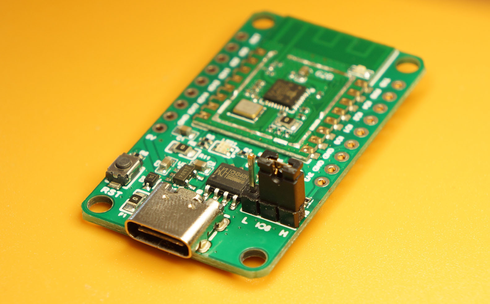
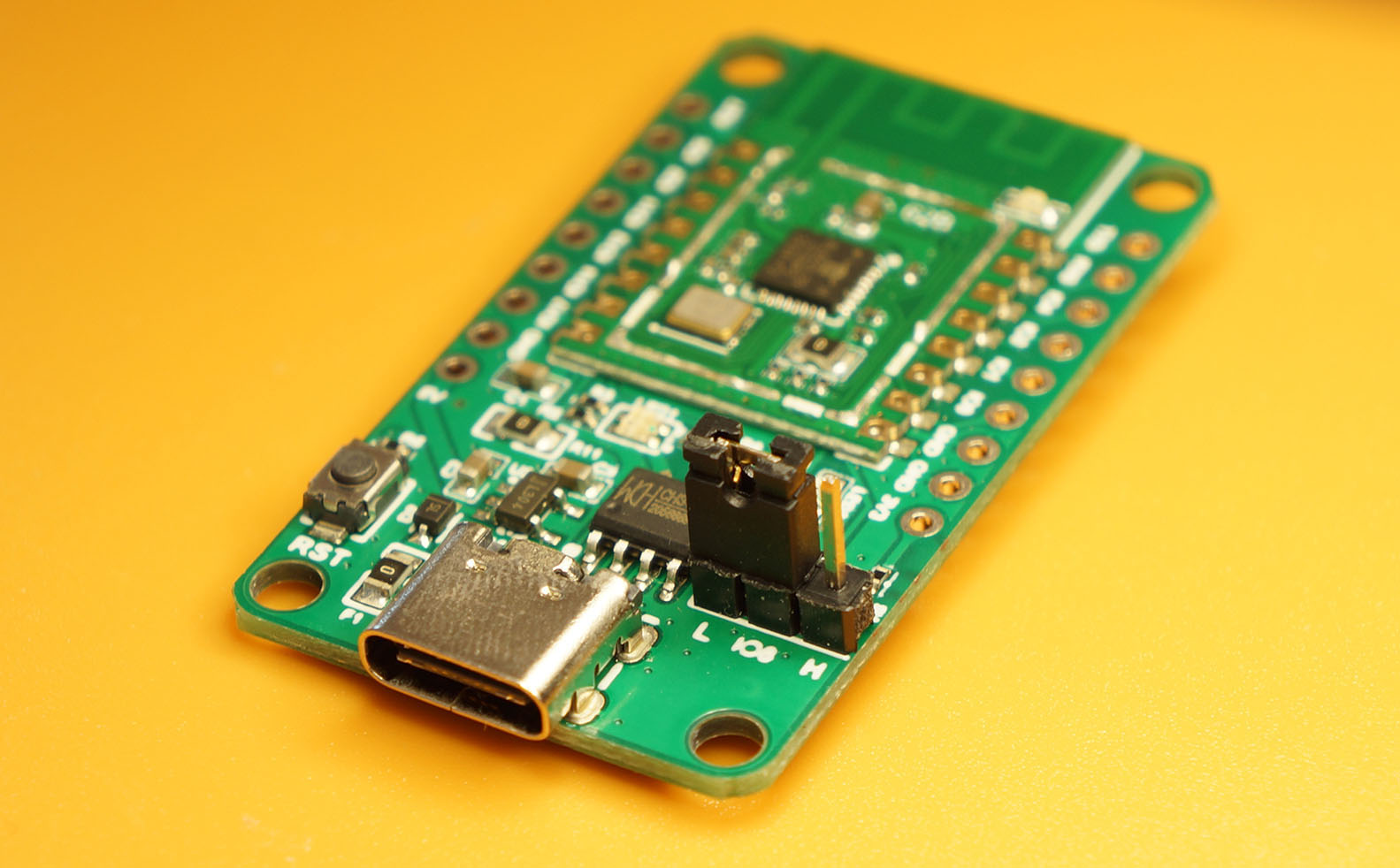
Let’s connect the IKEA Sensor to a RISC-V Microcontroller Board: Pine64 PineDio Stack BL604 (pic below) running on Apache NuttX operating system.
(Our code will run on ESP32 too)
Why are we doing this?
The sensor is affordable and available at our local IKEA store
Might be a fun intro to Embedded Programming
But some soldering needed! We’ll walk through the steps.
Apache NuttX is a tiny Linux-like operating system for microcontrollers. So our code will look familiar to Linux coders.
Eventually we’ll transmit the PM 2.5 data wirelessly over LoRaWAN to The Things Network. (Thanks to the onboard LoRa Transceiver on PineDio Stack)
Imagine connecting a community of Air Quality Sensors miles apart (because of LoRa’s long range). That would be super interesting for Environment Monitoring!
In a while we’ll dive into the code that talks to the IKEA Sensor…
But first let’s solder and wire up the IKEA Sensor!
Will it work with Arduino?
Check out these projects…
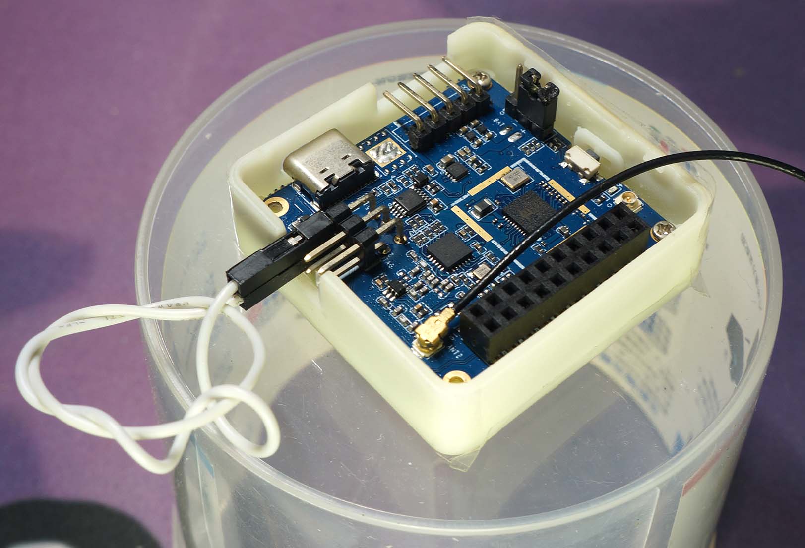
Pine64 PineDio Stack BL604 RISC-V Board
I found the VINDRIKTNING sensor at my local IKEA Store (IKEA Tampines Singapore) in the Lighting Section…
(Near the Air Purifiers. Wow IKEA has Air Purifiers now)
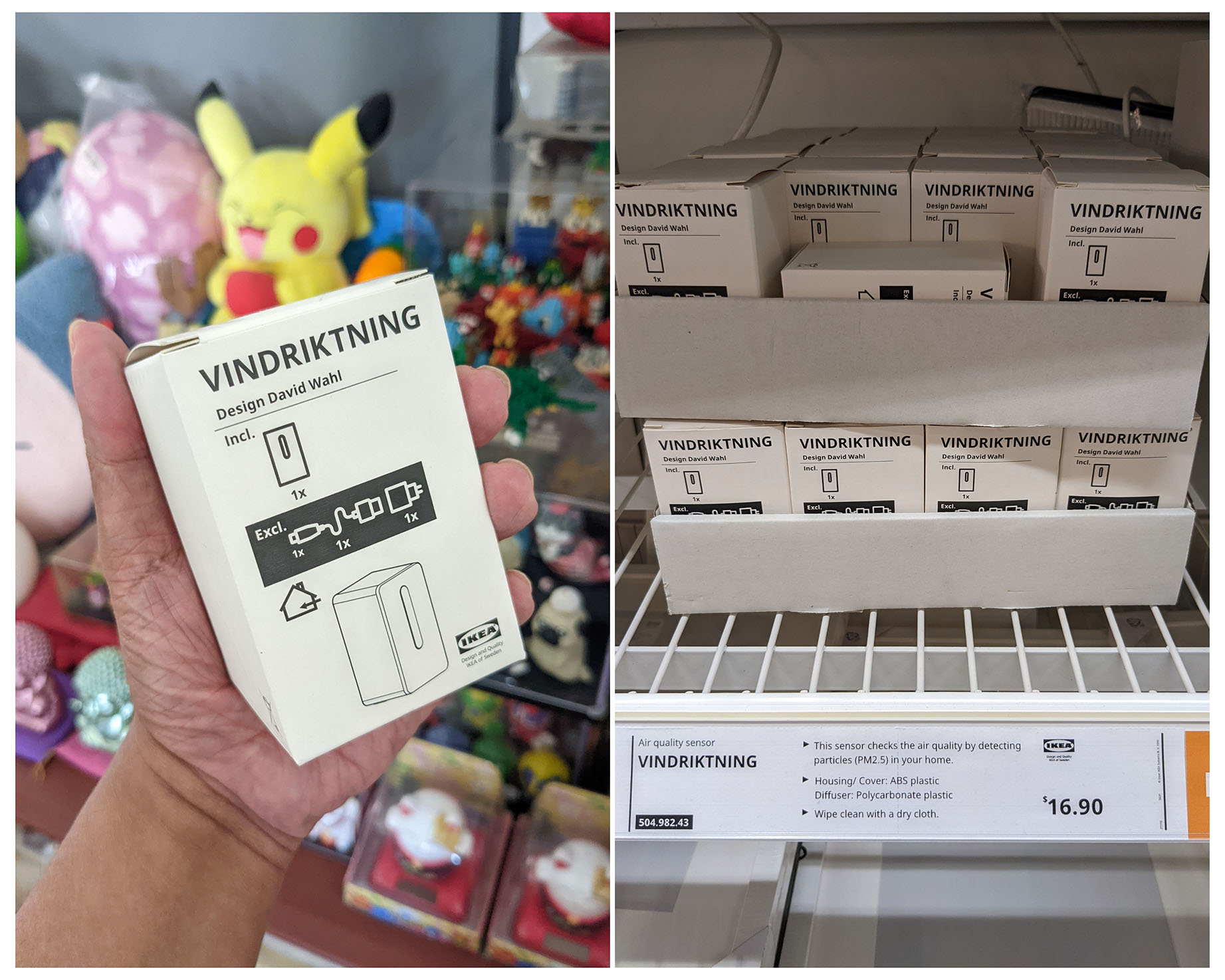
Connect the sensor to a USB-C Power Cable (not included) and it lights up in Red, Amber or Green…
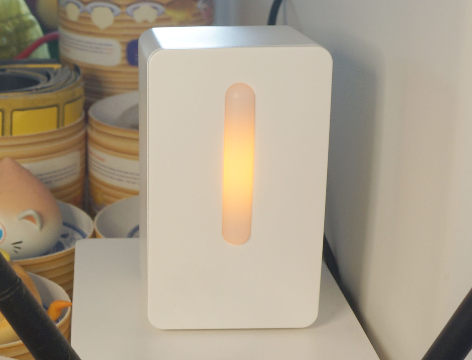
| Colour | PM 2.5 (μg/m³) | Air Quality |
|---|---|---|
| Green | 0 - 35 | Good |
| Amber | 36 - 85 | OK |
| Red | 86 and above | Not good |
(Watch it in action on YouTube)
Huh? This sensor outputs only 3 levels of Air Quality?
Actually the sensor is capable of measuring PM 2.5 from 0 to 1,000 μg/m³… Just that we need to wire it ourselves to get the PM 2.5 value.
The brilliant folks at the Home Assistant Project discovered that inside the IKEA Sensor is a PM1006 Infrared LED Particle Sensor…
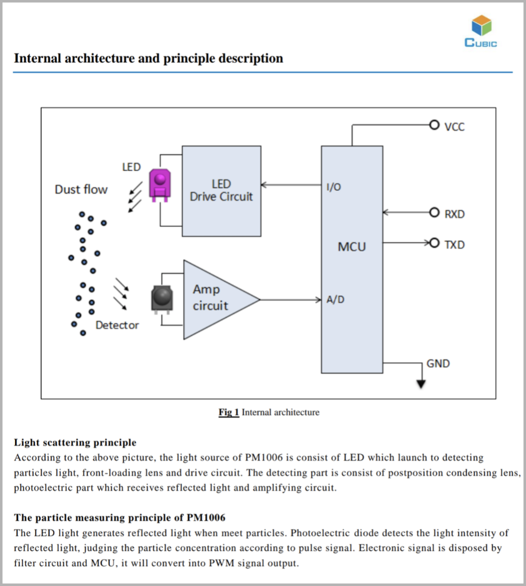
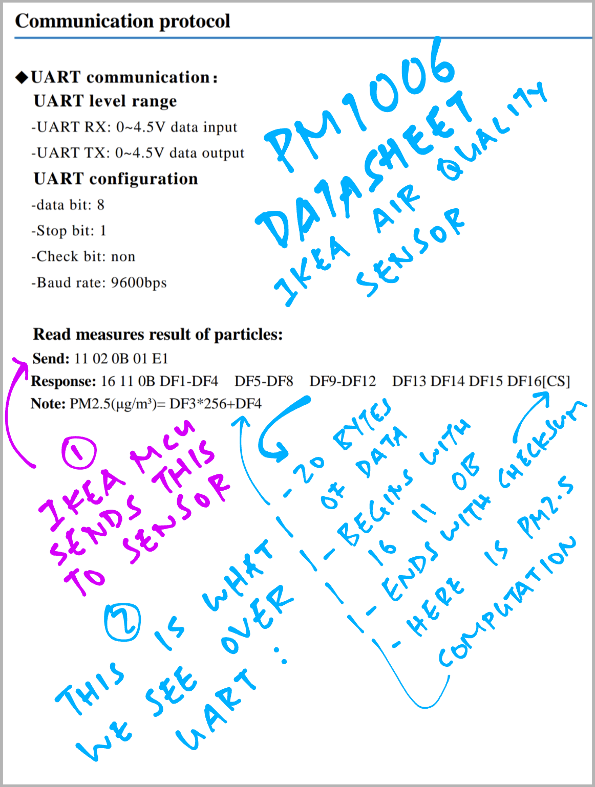
The PM1006 Sensor exposes a UART (Serial) Port that transmits the PM 2.5 value, encoded like so…
To get the PM 2.5 data, let’s wire up the UART Port with a little soldering.
(FYI: Inside the IKEA Sensor is another microcontroller that talks to PM1006. Periodically it triggers the PM1006 command that measures PM 2.5)
(Caution: The UART Port runs at 5V, not 3.3V)
Follow these steps to solder the UART (Serial) Port on the IKEA VINDRIKTNING Sensor (so we can access the PM 2.5 data)…
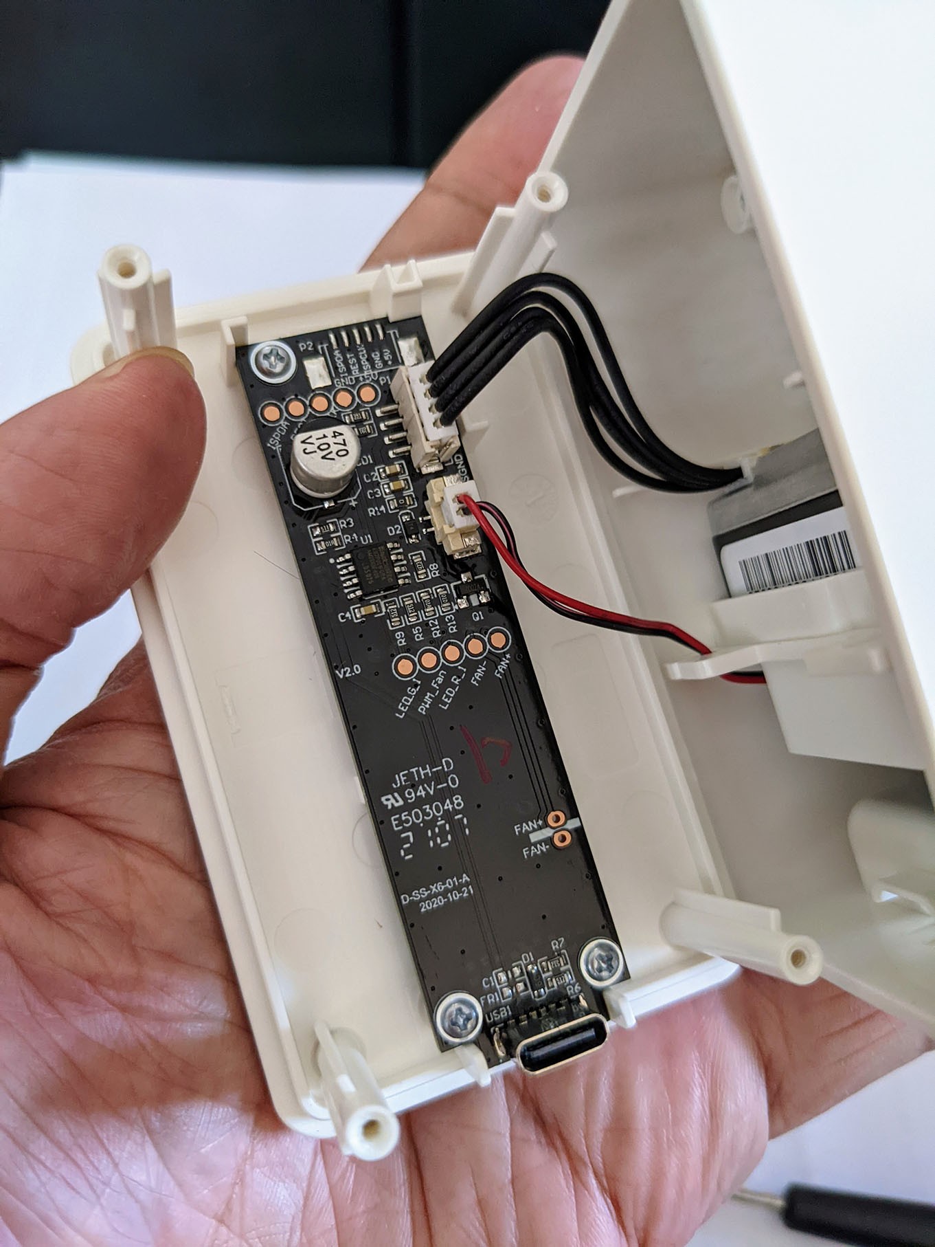
Unscrew the 4 screws on the back of the IKEA Sensor
Flip open the Back Cover to reveal the Circuit Board
(Pic above)
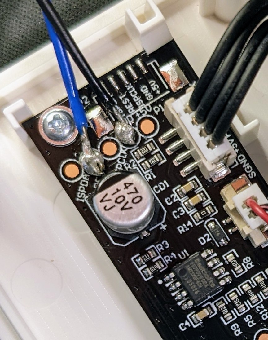
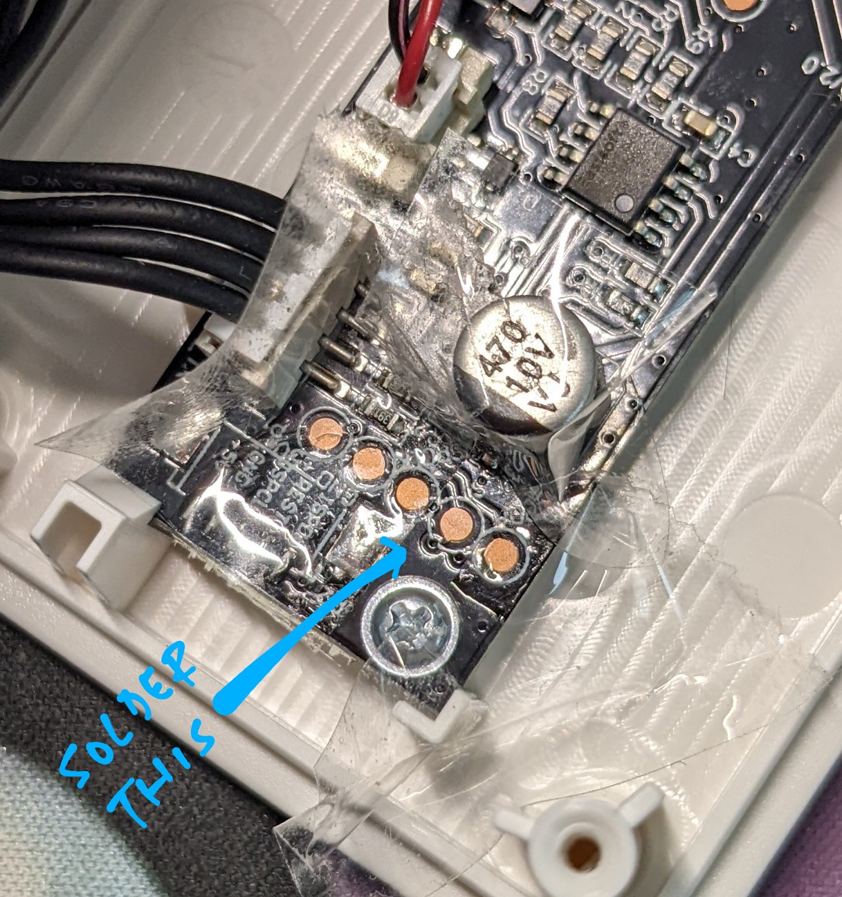
Solder these Circular Pads on the Circuit Board…
| IKEA Sensor | UART Pin | Wire Colour |
|---|---|---|
| REST | TX | Blue |
| GND | GND | Black |
(Pic below)
Stay clear of the Surface Mounted Components!
(Near the GND Pad)
Pardon my horrid soldering…
If you’re curious how I did it, check the Appendix for the Soldering Steps…
“Solder UART Port on IKEA VINDRIKTNING Air Quality Sensor”
(Hint: Use Sticky Tape and very fine Solder Wire)
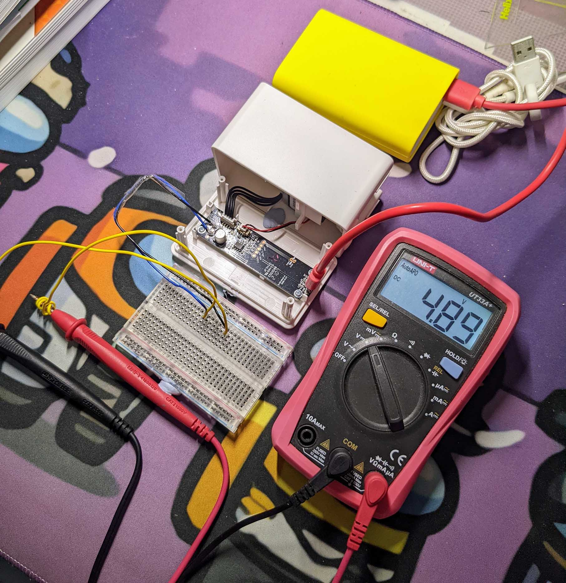
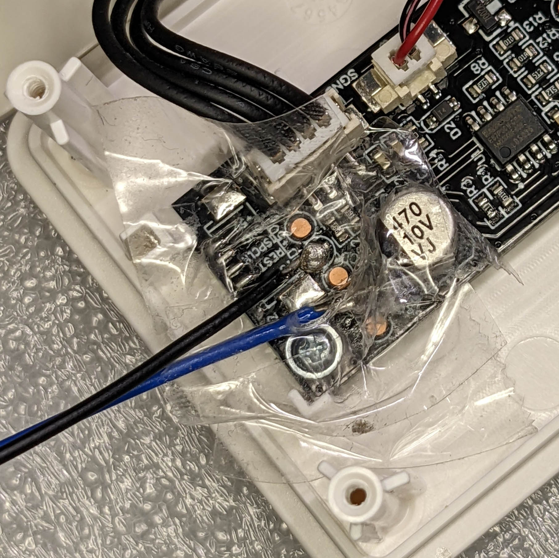
Test our handiwork with a Multimeter.
Note that the REST and GND Pins are exposed as tiny strips at the top of the pic below. Perfect for Multimeter Testing!
Optional: I used Bus Pirate to sniff the UART Port and inspect the data transmitted by the sensor. (See the details in the Appendix)
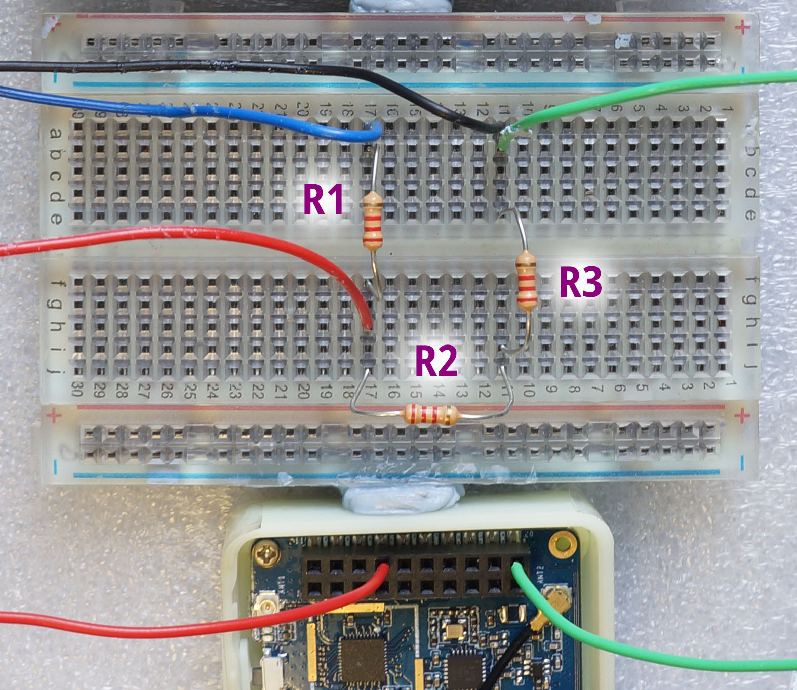
Now that we have exposed the UART Port on IKEA Air Quality Sensor, let’s connect it to our Microcontroller Board: PineDio Stack BL604
| From | To | Wire Colour |
|---|---|---|
| IKEA REST | Resistor R1 | Blue |
| IKEA GND | PineDio GND Pin 20 | Black |
| Resistor R1 | Resistor R2 | (Breadboard) |
| Resistor R2 | Resistor R3 | (Breadboard) |
| Resistor R1 | PineDio RX GPIO 3 / Pin 14 | Red |
| Resistor R3 | PineDio GND Pin 20 | Green |
| (Unused) | PineDio TX GPIO 4 / Pin 13 |
(R1, R2 and R3 are 3 Resistors with the same resistance, like 2.2 kΩ in the pic below)
(“PineDio Pin” refers to the 20-pin GPIO Connector on PineDio Stack)
Why the resistors?
That’s because IKEA Sensor’s UART Port runs at 5V, not 3.3V. (See this)
And our Microcontroller Board is not 5V Tolerant.
To convert the 5V UART Port to 3.3V, we connect 3 Resistors (of the same resistance) as a Voltage Divider…
How did we get GPIO 3 and 4?
The GPIO Pin Numbers for the UART Port (UART1) are defined in board.h
#define BOARD_UART_1_RX_PIN \
  (GPIO_INPUT     | GPIO_PULLUP | \
   GPIO_FUNC_UART | GPIO_PIN3)

#define BOARD_UART_1_TX_PIN \
  (GPIO_INPUT     | GPIO_PULLUP | \
   GPIO_FUNC_UART | GPIO_PIN4)
(Which pins can be used? See this)
For ESP32: The GPIO Pin Numbers for the UART Port (UART1) are defined in Kconfig and menuconfig…
config ESP32_UART1_TXPIN
int "UART1 Tx Pin"
default 10
range 0 39
config ESP32_UART1_RXPIN
int "UART1 Rx Pin"
default 9
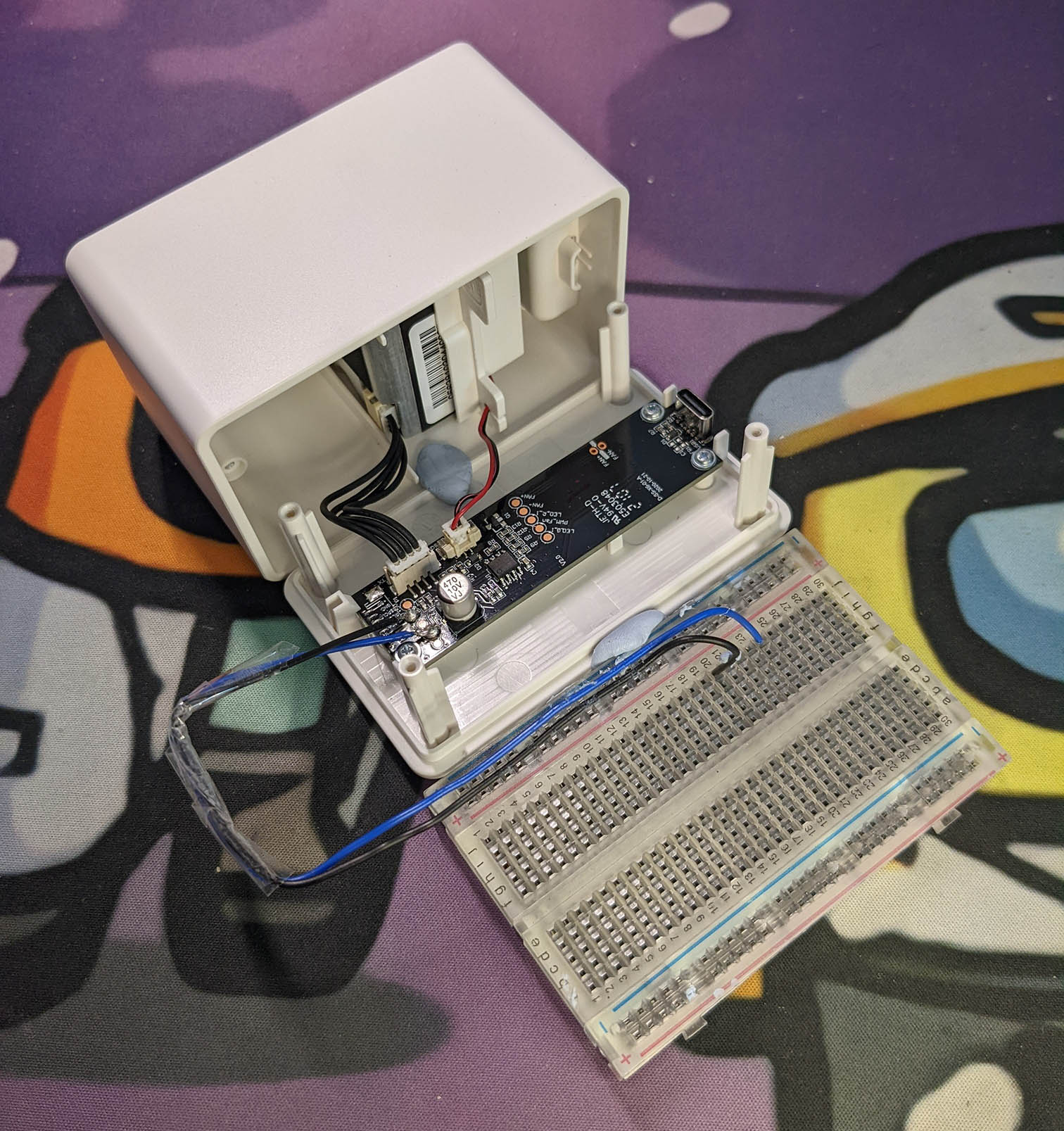
range 0 39Connect the USB Ports of IKEA Sensor and PineDio Stack to our computer.
(Remember: Only One Power Source for both gadgets!)
It looks messy with 2 USB Cables hanging off our computer, but we’ll live with it for now.
We’re all ready to read the PM 2.5 data from the IKEA Air Quality Sensor!
Let’s dive into the Source Code of our NuttX App that will read and process the PM 2.5 data…
But first: What’s inside the PM 2.5 data?
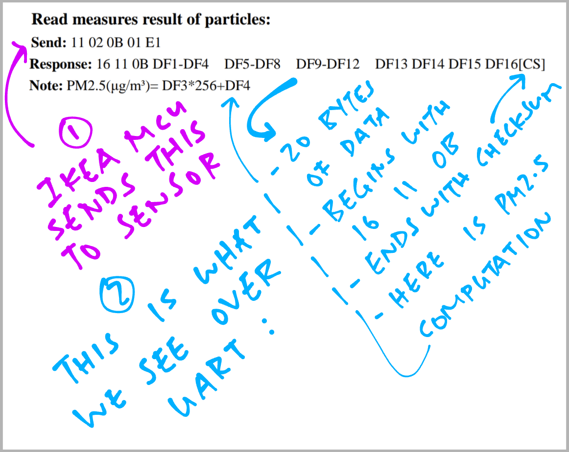
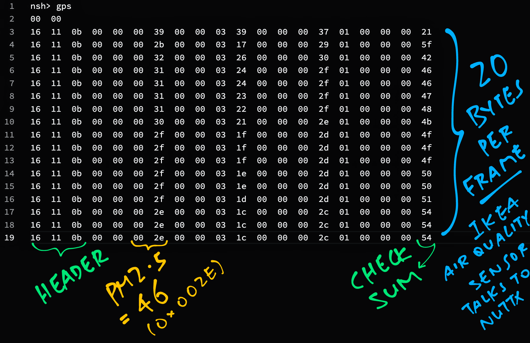
The IKEA Sensor transmits a stream of Sensor Data that looks like this…
16  11  0B  00  00  00  17  00  00  02  FF  00  00  00  21  02  00  00  0B  88
16  11  0B  00  00  00  17  00  00  02  FF  00  00  00  21  02  00  00  0B  88
16  11  0B  00  00  00  18  00  00  03  04  00  00  00  22  02  00  00  0B  80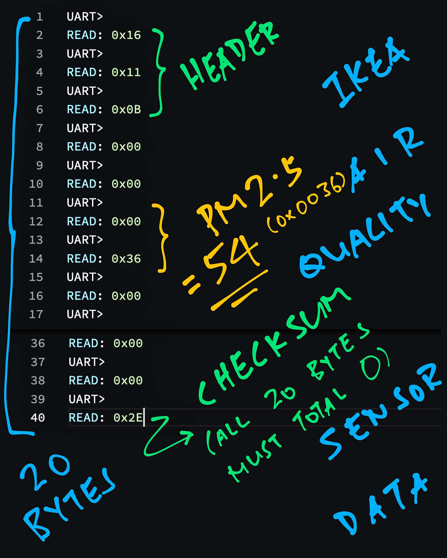
16 11 0B 00 00 00 18 00 00 03 04 00 00 00 22 02 00 00 0B 80See the pattern? The data comes in chunks of 20 bytes. Let’s call it a Sensor Data Frame.
Each Sensor Data Frame starts with this header…
16 11 0BIf we look back at the PM1006 Datasheet (pic above), we realise that the 20-byte Sensor Data Frame (“Response”) may be decoded like so…
| Field | Value |
|---|---|
| Header | 16 11 0B |
| (Unused) | 00 00 |
| PM 2.5 | 00 17 |
| (Unused) | 00 00 02 FF 00 00 |
| (Unused) | 00 21 02 00 00 0B |
| Checksum | 88 |
This gives the PM 2.5 value of 23 (0x0017).
What about the Checksum?
To validate the Checksum, all 20 bytes must add up to 0.
We skip the Sensor Data Frames that don’t add up to 0.
Thus we have a plan for reading and processing the PM 2.5 data…
Read the data into a 20-byte Sensor Data Frame
(We shift the data into the 20-byte frame, byte by byte)
Check the Header in the Sensor Data Frame
(Header should be 16 11 0B)
Validate the Checksum in the Sensor Data Frame
(All bytes must add up to 0)
Extract the PM 2.5 value from the Sensor Data Frame
(And process the PM 2.5 value)
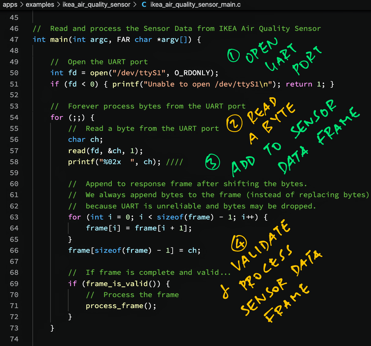
This is the Main Loop that runs the steps above: ikea_air_quality_sensor_main.c
//  Current data in the Sensor Data Frame (20 bytes)
static uint8_t frame[20];

//  Read and process the Sensor Data from IKEA Air Quality Sensor
int main(int argc, FAR char *argv[]) {

  //  Open the UART port
  int fd = open("/dev/ttyS1", O_RDONLY);
  if (fd < 0) { printf("Unable to open /dev/ttyS1\n"); return 1; }
We begin by opening the UART Port at /dev/ttyS1.
Next we loop forever, reading bytes from the UART Port and handling them…
  //  Forever process bytes from the UART port
  for (;;) {
    //  Read a byte from the UART port
    char ch;
    read(fd, &ch, 1);
    printf("%02x  ", ch);
After reading a byte, we shift it into the Sensor Data Frame (20 bytes)…
    //  Append to Sensor Data Frame after shifting the bytes.
    //  We always append bytes to the frame (instead of replacing bytes)
    //  because UART is unreliable and bytes may be dropped.
    for (int i = 0; i < sizeof(frame) - 1; i++) {
      frame[i] = frame[i + 1];
    }
    frame[sizeof(frame) - 1] = ch;
We check if the Sensor Data Frame contains a valid Header and Checksum…
    //  If frame is complete and valid...
    if (frame_is_valid()) {
      //  Process the frame
      process_frame();
    }
If the Sensor Data Frame is valid, we process the data in the frame.
Let’s jump into frame_is_valid and process_frame.
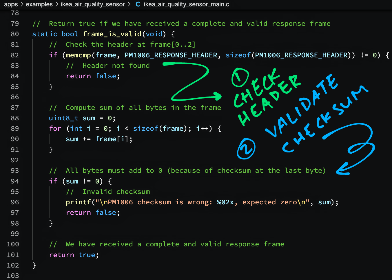
This is how we validate the Sensor Data Frame: ikea_air_quality_sensor_main.c
//  Header for Sensor Data Frame
static const uint8_t PM1006_RESPONSE_HEADER[] =
    { 0x16, 0x11, 0x0B };

//  Return true if we have received a complete and valid Sensor Data Frame
static bool frame_is_valid(void) {

  //  Check the header at frame[0..2]
  if (memcmp(frame, PM1006_RESPONSE_HEADER, sizeof(PM1006_RESPONSE_HEADER)) != 0) {
    //  Header not found
    return false;
  }
We verify that the Sensor Data Frame contains the Header: 16 11 0B
Next we sum up all the bytes in the Sensor Data Frame…
  //  Compute sum of all bytes in the frame
  uint8_t sum = 0;
  for (int i = 0; i < sizeof(frame); i++) {
    sum += frame[i];
  }
(Including the Checksum at the last byte)
And we verify that the sum is 0…
  //  All bytes must add to 0 (because of checksum at the last byte)
  if (sum != 0) {
    //  Invalid checksum
    printf("\nPM1006 checksum is wrong: %02x, expected zero\n", sum);
    return false;
  }
Now that the Sensor Data Frame is complete and valid…
  //  We have received a complete and valid response frame
  return true;
}
We proceed to process the PM 2.5 data inside the frame.
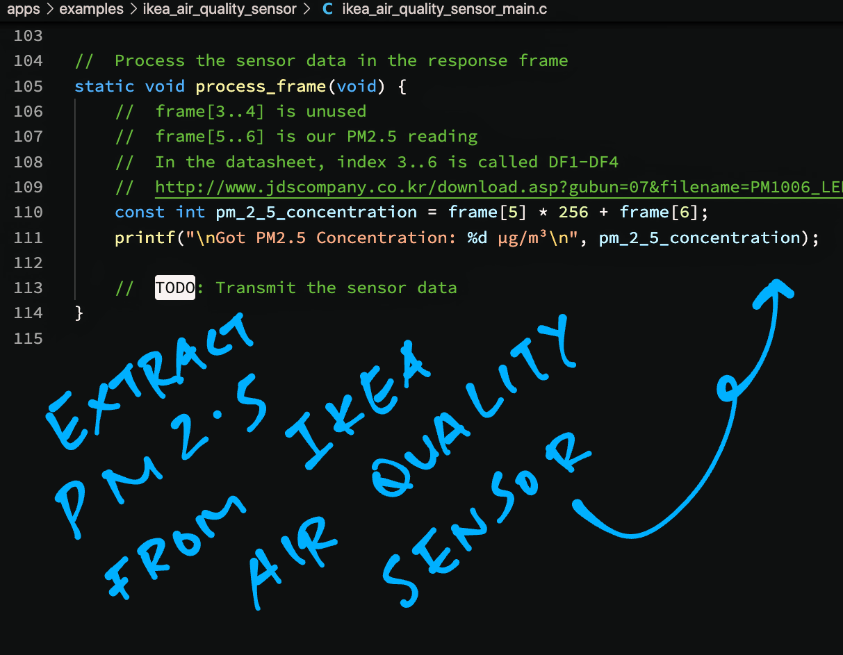
To process the Sensor Data Frame, we extract the PM 2.5 value from the frame: ikea_air_quality_sensor_main.c
//  Process the PM 2.5 data in the Sensor Data Frame
static void process_frame(void) {

  //  frame[3..4] is unused
  //  frame[5..6] is our PM2.5 reading
  //  In the datasheet, frame[3..6] is called DF1-DF4:
  //  https://github.com/arendst/Tasmota/files/7083662/PM1006_LED_PARTICLE_SENSOR_MODULE_SPECIFICATIONS.pdf

  const int pm_2_5_concentration =
    frame[5] * 256 +
    frame[6];
Right now we’re not really using the PM 2.5 data…
  //  TODO: Transmit the sensor data
  printf("\nGot PM2.5 Concentration: %d µg/m³\n", pm_2_5_concentration);
}
But in the next article we’ll transmit the data wirelessly over LoRaWAN to The Things Network.
(Thanks to the onboard LoRa Transceiver on PineDio Stack)
The code in our NuttX App was inspired by the Arduino and ESPHome modules for the IKEA Sensor.
We’re ready to run our NuttX App to read and process the PM 2.5 Sensor Data!
Follow these steps to build, flash and run NuttX…
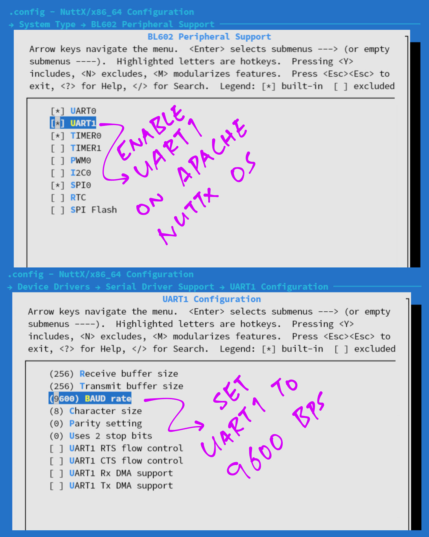
Remember to enable the UART1 Port /dev/ttyS1 and set it to 9,600 bps…
At the NuttX Shell, enter this command…
ls /devWe should see our UART Port configured at /dev/ttyS1…
/dev:
console
null
timer0
ttyS1
zero
Which is connected to our IKEA Sensor.
Enter this command to dump the output from our IKEA Sensor…
cat /dev/ttyS1We should see some meaningless ASCII data…
3(1>
2'0A
2%0C
1$/FBut that’s OK, it means that our IKEA Sensor is alive.
Finally enter this command to run our NuttX App for the IKEA Sensor…
ikea_air_quality_sensorWe should see the 20-byte Sensor Data Frames and the decoded PM 2.5 values…
16  11  0b  00  00  00  17  00  00  02  ff  00  00  00  21  02  00  00  0b  88
Got PM2.5 Concentration: 23 µg/m³

16  11  0b  00  00  00  18  00  00  03  04  00  00  00  22  02  00  00  0b  80
Got PM2.5 Concentration: 24 µg/m³

16  11  0b  00  00  00  17  00  00  03  01  00  00  00  21  02  00  00  0b  85
Got PM2.5 Concentration: 23 µg/m³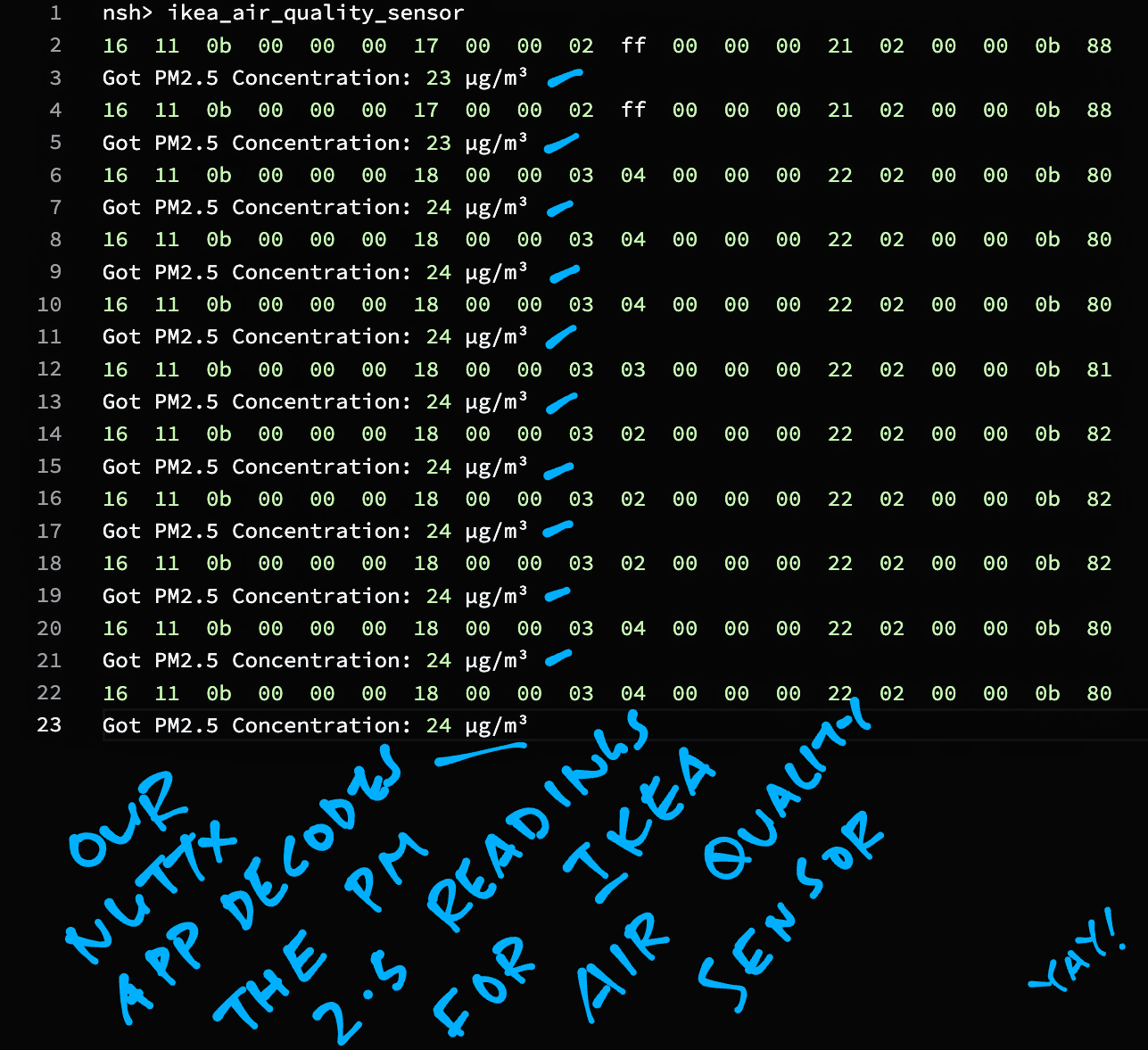
Congratulations we have successfully read the PM 2.5 values from the IKEA VINDRIKTNING Air Quality Sensor! 🎉
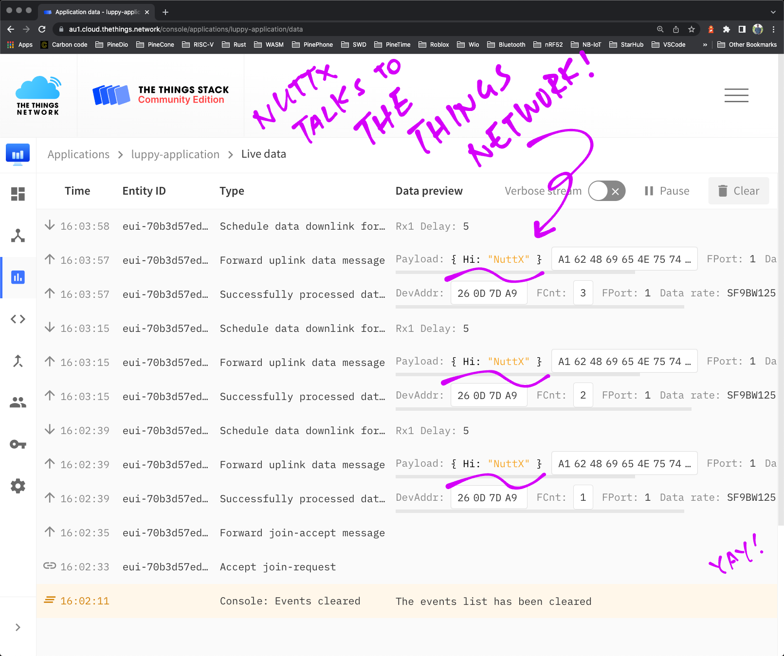
In the next article we shall transmit the PM 2.5 data wirelessly over LoRaWAN to The Things Network. (Thanks to the onboard LoRa Transceiver on PineDio Stack)
Imagine connecting a community of Air Quality Sensors miles apart (because of LoRa’s long range). That would be super interesting for Environment Monitoring!
(We’ll visualise the PM 2.5 data with Prometheus and Grafana)
Stay Tuned!
Many Thanks to my GitHub Sponsors for supporting my work! This article wouldn’t have been possible without your support.
Got a question, comment or suggestion? Create an Issue or submit a Pull Request here…
This article is the expanded version of this Twitter Thread
According to the PM1006 Datasheet, the UART Port runs at 5V Logic Level (instead of 3.3V, see pic above).
Apparently some folks are using the 5V UART Port just fine without converting to 3.3V. (See this)
But to protect our microcontroller (which is not 5V Tolerant) we need a Voltage Divider…
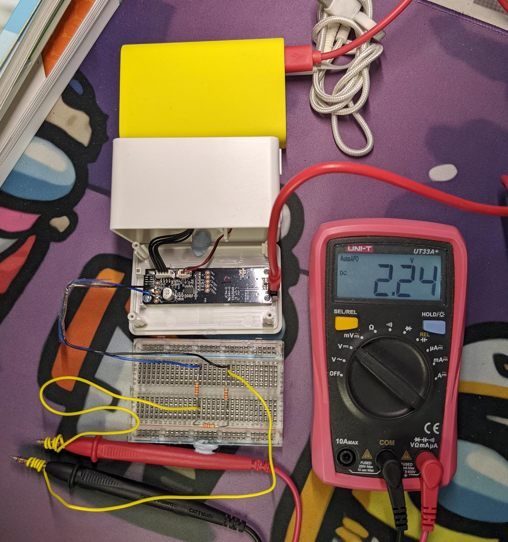
(With 3 resistors of the same value)
The pic shows it’s not exactly 3.3V, but as long as our Logic High is above 2V, we should be fine. (See this)
Each Sensor Data Frame has 20 bytes. Why are so many bytes unused?
IKEA Air Quality Sensor uses the PM1006 Sensor, which is a cheaper version of PM1006K.
On PM1006K we get more data fields: PM 1.0 and PM 10. These fields are not available on PM1006, hence we have unused bytes in the Sensor Data Frame.
Here’s how I soldered the UART (Serial) Port on the IKEA VINDRIKTNING Air Quality Sensor.
(Sorry I’m terribly inexperienced with soldering 🙏)
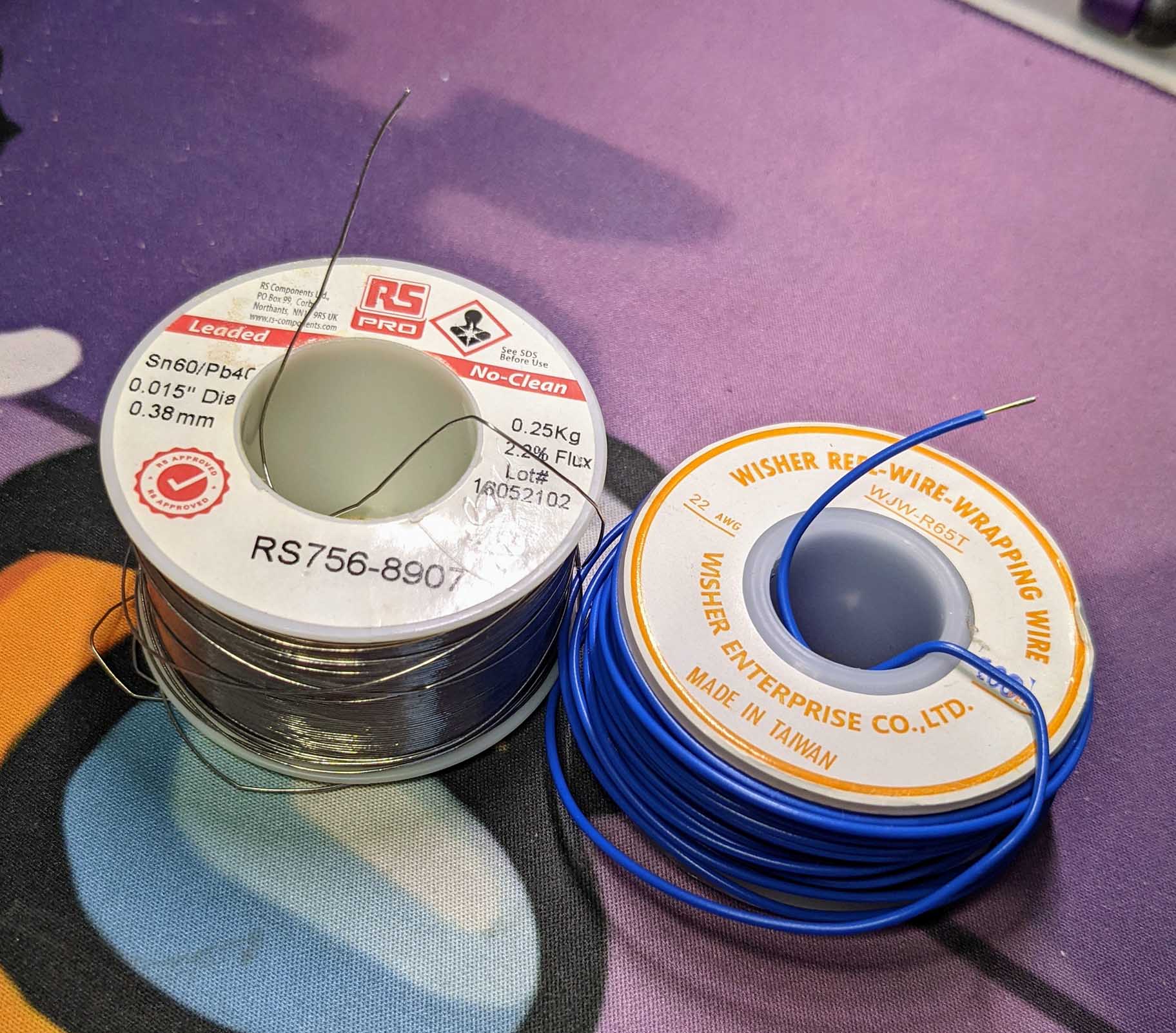
I used very fine Solder Wire (0.38 mm diameter) because it creates very tiny, precise blobs of solder. And 22 AWG Solid Core Wire (Blue and Black).
(See pic above)
Here are the steps…
Unscrew the Back Cover to reveal the Circuit Board
We’ll solder these Circular Pads on the Circuit Board…
| IKEA Sensor | UART Pin | Wire Colour |
|---|---|---|
| REST | TX | Blue |
| GND | GND | Black |
We start with the REST Pad.
Mask out with Sticky Tape all the parts around the REST Pad that should NOT be soldered.
With our Soldering Iron, drop a tiny blob of Molten Solder on the REST Pad.
(Very fine Solder Wire really helps)
Carefully place our Blue Solid Core Wire (or similar) on top of the Solder Blob.
(Now hardened)
Gently tap our Soldering Iron on top of the wire.
The wire should sink into the Molten Blob of Solder.
Quickly adjust the wire to make sure it doesn’t touch any components on the Circuit Board.
When cooled, the wire stays in the hardened Solder Blob.
Now we solder the GND Pad.
Mask out with Sticky Tape all the parts around the GND Pad that should NOT be soldered.
(Especially the Surface Mounted Components near the GND Pad)
Repeat the earlier steps to solder the GND Pad with our Black Solid Core Wire.
Stay clear of the Surface Mounted Components!
Remove the Sticky Tape. We’re done!
Bend the Solid Core Wires and bind them with Sticky Tape so they don’t get dislodged easily.
Test our handiwork with a Multimeter.
(The UART Port runs at 5V, not 3.3V)
Before testing with Apache NuttX OS, we sniffed the UART Port on IKEA VINDRIKTNING Air Quality Sensor with Bus Pirate.
Connect Bus Pirate to the IKEA Sensor as follows…
| Bus Pirate | IKEA Sensor | Wire Colour |
|---|---|---|
| Data In (MISO) | REST | Blue |
| GND | GND | Black |
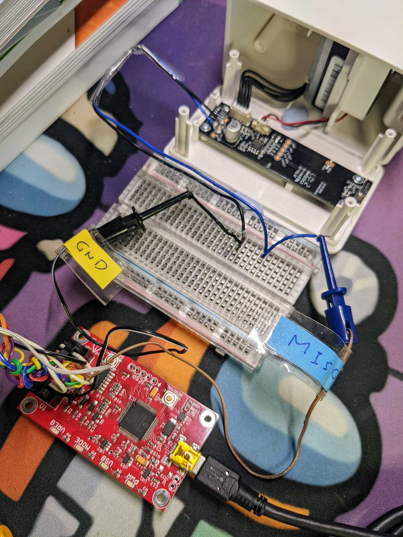
Connect the USB Ports of the IKEA Sensor and Bus Pirate to the same computer. Remember: Only One Power Source for both gadgets!
Enter these Bus Pirate commands to capture the UART output from the IKEA Sensor (9600 bps, 8 bits, no parity, 1 stop bit)…
HiZ> m

1. HiZ
2. 1-WIRE
3. UART
4. I2C
5. SPI
6. 2WIRE
7. 3WIRE
8. KEYB
9. LCD
10. PIC
11. DIO
x. exit(without change)
(1)> 3

Set serial port speed: (bps)
 1. 300
 2. 1200
 3. 2400
 4. 4800
 5. 9600
 6. 19200
 7. 38400
 8. 57600
 9. 115200
10. Input Custom BAUD
11. Auto-Baud Detection (Activity Required)
(1)> 5

Data bits and parity:
 1. 8, NONE *default
 2. 8, EVEN
 3. 8, ODD
 4. 9, NONE
(1)>

Stop bits:
 1. 1 *default
 2. 2
(1)>

Receive polarity:
 1. Idle 1 *default
 2. Idle 0
(1)>

Select output type:
 1. Open drain (H=Hi-Z, L=GND)
 2. Normal (H=3.3V, L=GND)
(1)>

Clutch disengaged!!!
To finish setup, start up the power supplies with command 'W'
Ready

UART> W
POWER SUPPLIES ON
Clutch engaged!!!(More about Bus Pirate interfacing with UART)
To see the ASCII Output from the IKEA Sensor, enter this Bus Pirate command…
UART> (2)
Raw UART input
Any key to exit
<@:
<B:
[6C:;8
[9C:;8
[12C9:7
[16C997!
[20C987"To see the Binary Output from the IKEA Sensor, enter this…
UART> {
UART LIVE DISPLAY, } TO STOP
We should see the 20-byte Sensor Data Frames with PM 2.5 encoded inside…
(For BL602, BL604 and ESP32)
Below are the steps to build, flash and run NuttX on BL602, BL604 and ESP32.
The instructions below will work on Linux (Ubuntu), WSL (Ubuntu) and macOS.
(Instructions for other platforms)
To use the IKEA Air Quality Sensor with NuttX, download the modified source code for NuttX OS and NuttX Apps…
mkdir nuttx
cd nuttx
git clone --recursive --branch ikea https://github.com/lupyuen/nuttx nuttx
git clone --recursive --branch ikea https://github.com/lupyuen/nuttx-apps apps
Or if we prefer to add the IKEA Air Quality Sensor App to our NuttX Project, follow these instructions…
(For PineDio Stack BL604: The app is already preinstalled)
Now we configure our NuttX project…
Install the build prerequisites…
Configure the build…
cd nuttx

## For BL602: Configure the build for BL602
./tools/configure.sh bl602evb:nsh

## For PineDio Stack BL604: Configure the build for BL604
./tools/configure.sh bl602evb:pinedio

## For ESP32: Configure the build for ESP32.
## TODO: Change "esp32-devkitc" to our ESP32 board.
./tools/configure.sh esp32-devkitc:nsh

## Edit the Build Config
make menuconfig
Enable UART1…
For BL602 / BL604: Check the box for “System Type” → “BL602 Peripheral Support” → “UART1”
For ESP32: Check the box for “System Type” → “ESP32 Peripheral Select” → “UART 1”
Hit “Exit” until the Top Menu appears. (“NuttX/x64_64 Configuration”)
Set UART1 to 9,600 bps…
Select “Device Drivers” → “Serial Driver Support” → “UART1 Configuration”
Set “BAUD rate” to 9600
Hit “Exit” until the Top Menu appears. (“NuttX/x64_64 Configuration”)
Enable cat and ls commands…
Select “Application Configuration” → “NSH Library” → “Disable Individual commands”
Uncheck “Disable cat”
Uncheck “Disable ls”
Hit “Exit” until the Top Menu appears. (“NuttX/x64_64 Configuration”)
Enable Logging and Assertion Checks…
Select “Build Setup” → “Debug Options”
Check the boxes for the following…
Enable Debug Features
Enable Error Output
Enable Warnings Output
Enable Debug Assertions
Hit “Exit” until the Top Menu appears. (“NuttX/x64_64 Configuration”)
Save the configuration and exit menuconfig
The IKEA Sensor will be connected to NuttX at /dev/ttyS1
Follow these steps to build NuttX for BL602, BL604 or ESP32…
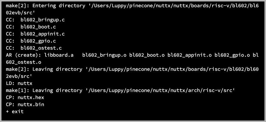
To build NuttX, enter this command…
makeWe should see…
LD: nuttx
CP: nuttx.hex
CP: nuttx.binFor WSL: Copy the NuttX Firmware to the c:\blflash directory in the Windows File System…
##  /mnt/c/blflash refers to c:\blflash in Windows
mkdir /mnt/c/blflash
cp nuttx.bin /mnt/c/blflash
For WSL we need to run blflash under plain old Windows CMD (not WSL) because it needs to access the COM port.
In case of problems, refer to the NuttX Docs…
For ESP32: See instructions here (Also check out this article)
For BL602 / BL604: Follow these steps to install blflash…
We assume that our Firmware Binary File nuttx.bin has been copied to the blflash folder.
Set BL602 / BL604 to Flashing Mode and restart the board…
For PineDio Stack BL604:
Set the GPIO 8 Jumper to High (Like this)
Disconnect the USB cable and reconnect
Or use the Improvised Reset Button (Here’s how)
For PineCone BL602:
Set the PineCone Jumper (IO 8) to the H Position (Like this)
Press the Reset Button
For BL10:
Connect BL10 to the USB port
Press and hold the D8 Button (GPIO 8)
Press and release the EN Button (Reset)
Release the D8 Button
For Ai-Thinker Ai-WB2, Pinenut and MagicHome BL602:
Disconnect the board from the USB Port
Connect GPIO 8 to 3.3V
Reconnect the board to the USB port
Enter these commands to flash nuttx.bin to BL602 / BL604 over UART…
## For Linux: Change "/dev/ttyUSB0" to the BL602 / BL604 Serial Port
blflash flash nuttx.bin \
--port /dev/ttyUSB0
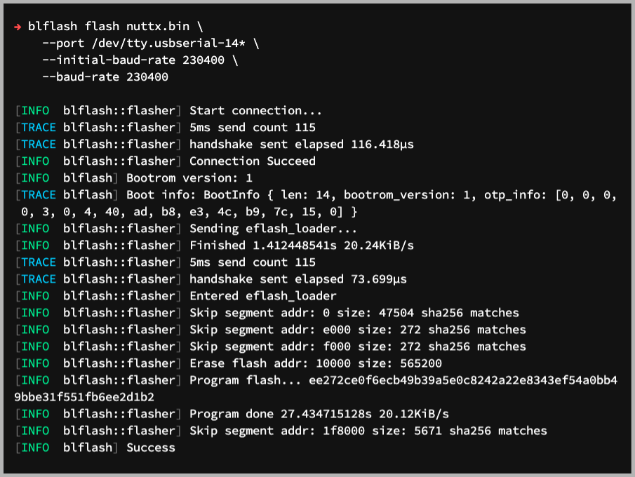
## For macOS: Change "/dev/tty.usbserial-1410" to the BL602 / BL604 Serial Port
blflash flash nuttx.bin \
--port /dev/tty.usbserial-1410 \
--initial-baud-rate 230400 \
--baud-rate 230400
## For Windows: Change "COM5" to the BL602 / BL604 Serial Port
blflash flash c:\blflash\nuttx.bin --port COM5For WSL: Do this under plain old Windows CMD (not WSL) because blflash needs to access the COM port.
(Flashing WiFi apps to BL602 / BL604? Remember to use bl_rfbin)
(More details on flashing firmware)
For ESP32: Use Picocom to connect to ESP32 over UART…
picocom -b 115200 /dev/ttyUSB0For BL602 / BL604: Set BL602 / BL604 to Normal Mode (Non-Flashing) and restart the board…
For PineDio Stack BL604:
Set the GPIO 8 Jumper to Low (Like this)
Disconnect the USB cable and reconnect
Or use the Improvised Reset Button (Here’s how)
For PineCone BL602:
Set the PineCone Jumper (IO 8) to the L Position (Like this)
Press the Reset Button
For BL10:
For Ai-Thinker Ai-WB2, Pinenut and MagicHome BL602:
Disconnect the board from the USB Port
Connect GPIO 8 to GND
Reconnect the board to the USB port
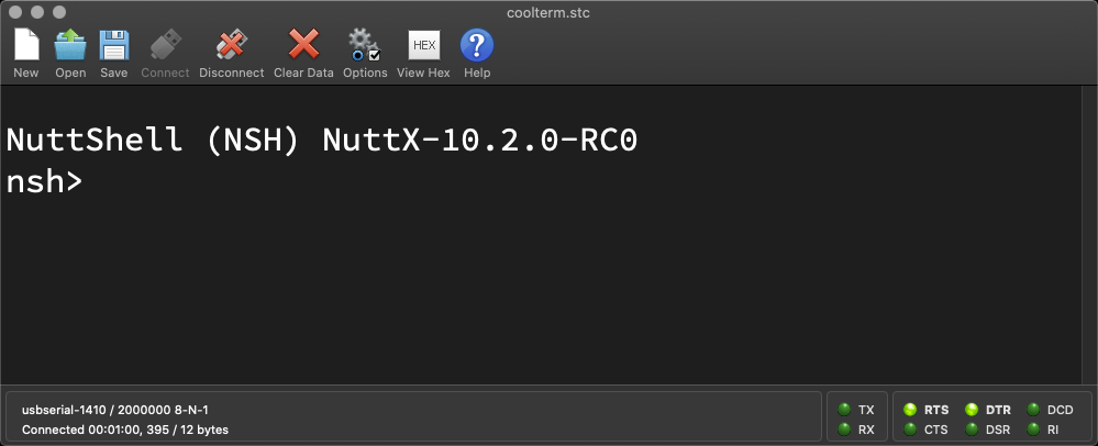
After restarting, connect to BL602 / BL604’s UART Port at 2 Mbps like so…
For Linux:
screen /dev/ttyUSB0 2000000For macOS: Use CoolTerm (See this)
For Windows: Use putty (See this)
Alternatively: Use the Web Serial Terminal (See this)
Press Enter to reveal the NuttX Shell…
NuttShell (NSH) NuttX-10.2.0-RC0
nsh>
Congratulations NuttX is now running on BL602 / BL604!
(More details on connecting to BL602 / BL604)
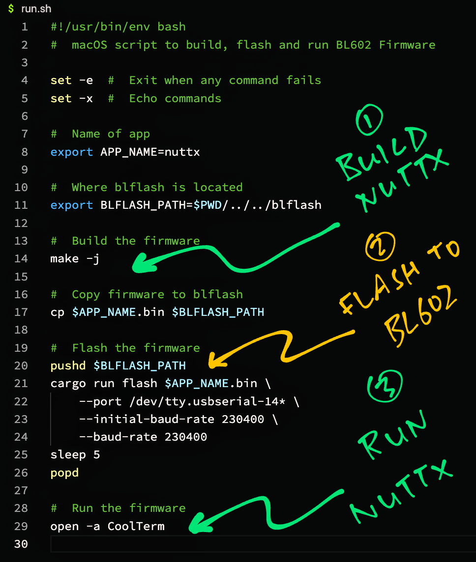
macOS Tip: Here’s the script I use to build, flash and run NuttX on macOS, all in a single step: run.sh
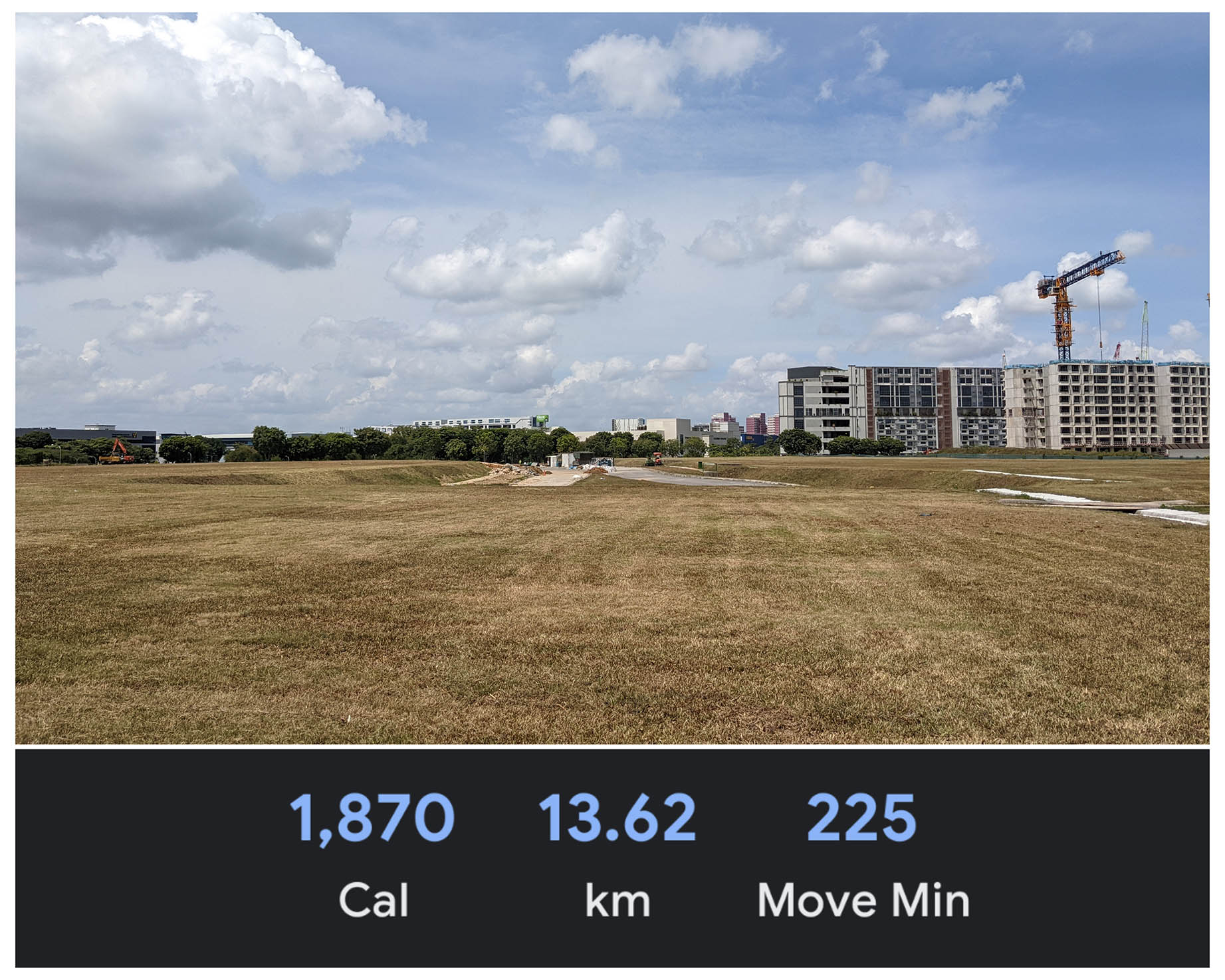
Trekking 13 km to IKEA on the horizon in search of VINDRIKTNING