📝 3 May 2022
PineDio Stack BL604 (Pine64’s newest RISC-V board) has an interesting problem on Apache NuttX RTOS…
Too Many GPIOs!
Let’s fix this with a GPIO Expander.
Why too many GPIOs?
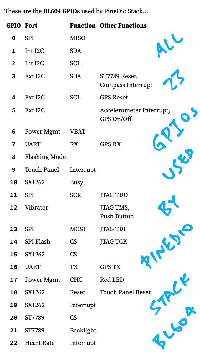
All 23 GPIOs on PineDio Stack BL604 are wired up…
And we need easy access to all GPIOs as our devs create NuttX Drivers and Apps for PineDio Stack.
(See pic below)
NuttX can’t handle 23 GPIOs?
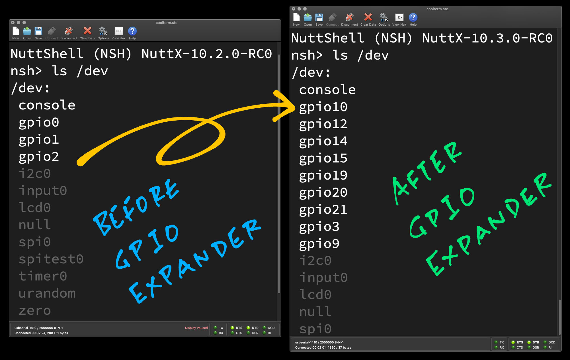
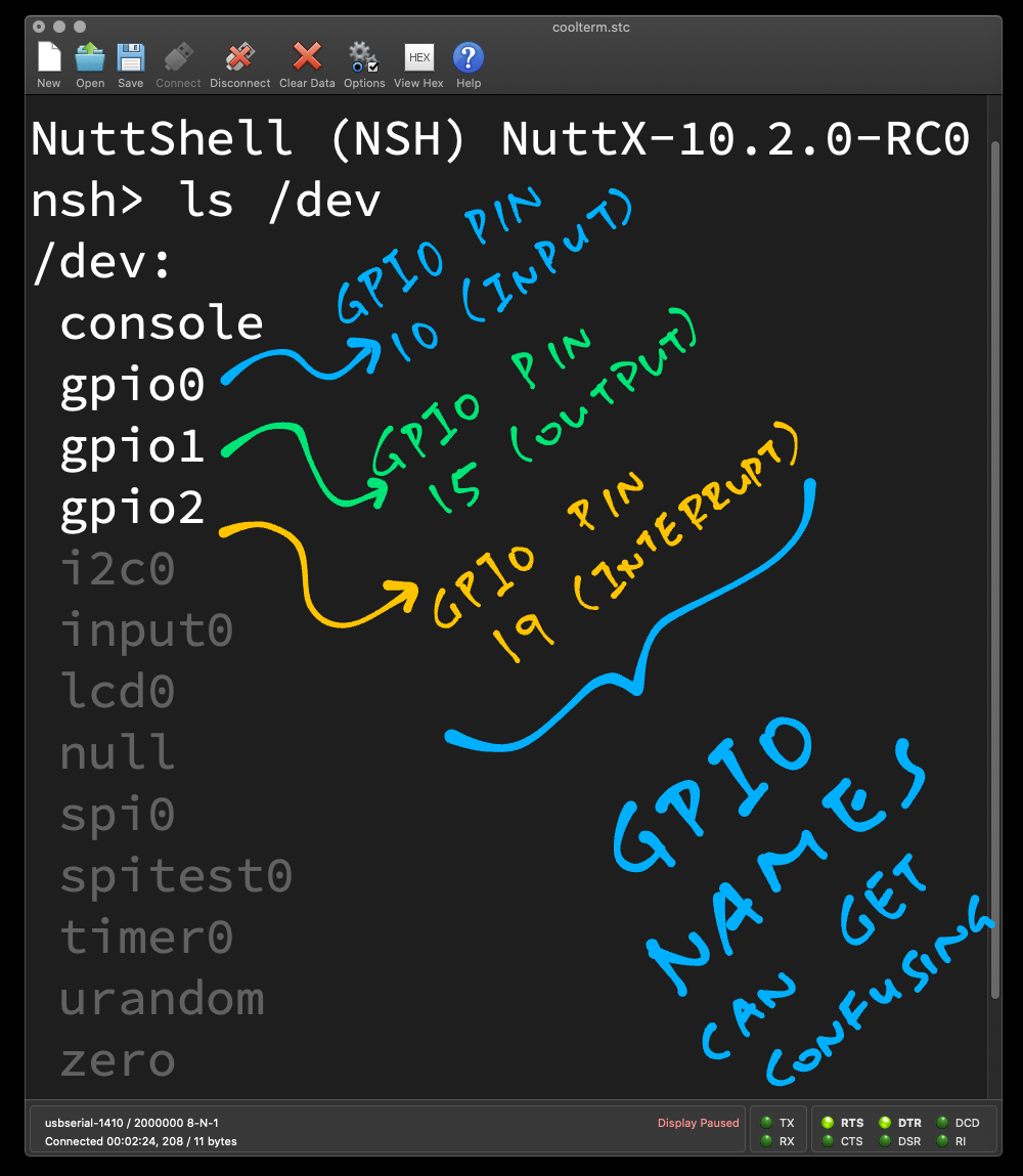
Well it gets messy. Without GPIO Expander, BL604 on NuttX supports one GPIO Input, one GPIO Output and one GPIO Interrupt.
And they are named sequentially (Input first, then Output, then Interrupt)…
/dev/gpio0: GPIO Input
/dev/gpio1: GPIO Output
/dev/gpio2: GPIO Interrupt
(See pic above)
This looks OK?
Until we realise that they map to totally different GPIO Pins on PineDio Stack!
| GPIO Device | BL604 GPIO Pin | Function |
|---|---|---|
| /dev/gpio0 | GPIO Pin 10 | SX1262 Busy |
| /dev/gpio1 | GPIO Pin 15 | SX1262 Chip Select |
| /dev/gpio2 | GPIO Pin 19 | SX1262 Interrupt |
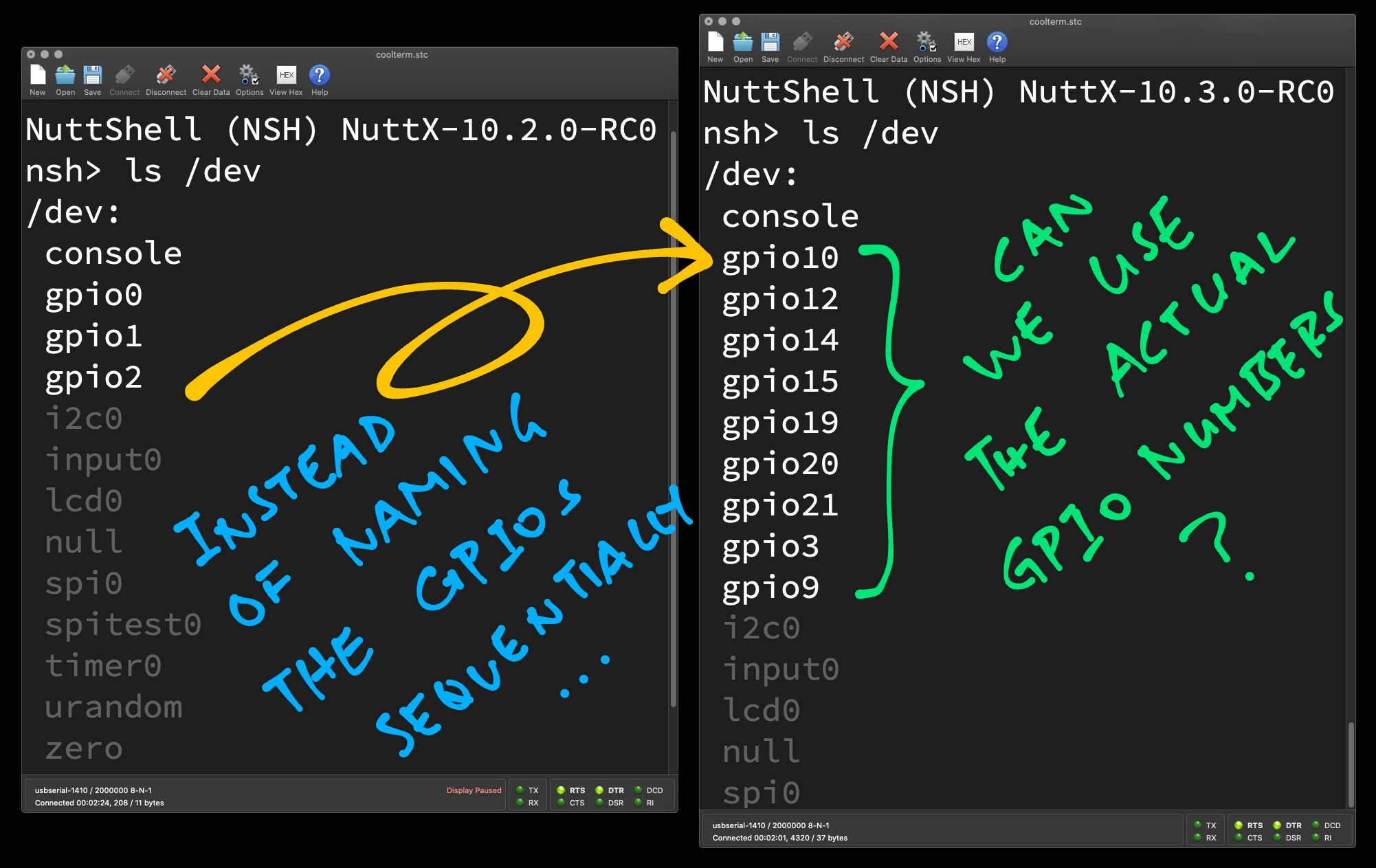
Extend this to 23 GPIOs and we have a mapping disaster!
Let’s simplify this setup and map GPIO Pins 0 to 22 as “/dev/gpio0” to “/dev/gpio22”. We’ll do this with a GPIO Expander.
(See pic above)
What’s a GPIO Expander?
NuttX lets us create I/O Expander Drivers that will manage many GPIOs…
Well BL604 looks like a Big Bag o’ GPIOs. Why not create a GPIO Expander that will manage all 23 GPIOs?
(Other microcontrollers might also need a GPIO Expander… Like CH32V307, which has 80 GPIOs!)
So we’re just renumbering GPIOs?
Above and beyond that, our BL604 GPIO Expander serves other functions…
Attach and detach GPIO Interrupt Callbacks
Validate GPIO Pin Numbers at startup
But skip the GPIOs reserved for UART, I2C and SPI
(That’s why we have GPIO gaps in the pic above)
Let’s dive in!
What’s this BL602 EVB?
In NuttX, BL602 EVB (“Evaluation Board”) provides the Board-Specific Functions for PineDio Stack and other BL602 / BL604 boards…
What’s inside BL602 EVB?
The important parts of BL602 EVB are…
Pin Definitions: board.h
Defines the pins for the GPIO, UART, I2C, SPI and PWM ports.
Bring-Up: bl602_bringup.c
Starts the NuttX Drivers and the GPIO / UART / I2C / SPI / PWM ports.
EVB GPIO Driver: bl602_gpio.c
Implements the GPIO Input, Output and Interrupt ports.
Calls the BL602 GPIO Driver.
In a while we’ll study the limitations of BL602 EVB, to understand why we created the BL602 GPIO Expander.
Wait… Where’s the rest of the BL602 stuff?
The Architecture-Specific Functions for BL602 and BL604 are located at…
This includes the low-level drivers for GPIO, UART, I2C, SPI, PWM, …
We’re hunky dory with these drivers, though we’ve made tiny mods like for SPI Device Table.
In BL602 EVB, this is how we define the pins for GPIO / UART / I2C / SPI / PWM: board.h
#define BOARD_NGPIOIN  1  //  Number of GPIO Input pins
#define BOARD_NGPIOOUT 1  //  Number of GPIO Output pins
#define BOARD_NGPIOINT 1  //  Number of GPIO Interrupt pins

//  GPIO Input: GPIO 10
#define BOARD_GPIO_IN1  (GPIO_PIN10 | GPIO_INPUT | GPIO_FLOAT | GPIO_FUNC_SWGPIO)

//  GPIO Output: GPIO 15
#define BOARD_GPIO_OUT1 (GPIO_PIN15 | GPIO_OUTPUT | GPIO_PULLUP | GPIO_FUNC_SWGPIO)

//  GPIO Interrupt: GPIO 19
#define BOARD_GPIO_INT1 (GPIO_PIN19 | GPIO_INPUT | GPIO_FLOAT | GPIO_FUNC_SWGPIO)
(See the UART / I2C / SPI / PWM Pins)
A couple of issues…
BL602 EVB strangely limits us to one GPIO Input, one GPIO Output and one GPIO Interrupt
We could extend this GPIO Limit, but we’ll have to modify the EVB GPIO Driver, which sounds odd
BL602 EVB always maps sequentially the GPIO Pins like so: GPIO Input, then GPIO Output, then GPIO Interrupt (pic above)…
/dev/gpio0: GPIO Input (GPIO 10)
/dev/gpio1: GPIO Output (GPIO 15)
/dev/gpio2: GPIO Interrupt (GPIO 19)
Which becomes super confusing when we map all 23 GPIOs on PineDio Stack.
(Especially when our new devs are now creating NuttX Drivers and Apps for PineDio Stack)
What happens if we reuse the GPIOs by mistake? BL602 EVB will silently allow this. Which ain’t right!
//  GPIO Input: GPIO 10
#define BOARD_GPIO_IN1  (GPIO_PIN10 | GPIO_INPUT | GPIO_FLOAT | GPIO_FUNC_SWGPIO)

//  GPIO Output: Also GPIO 10 (Oops!)
#define BOARD_GPIO_OUT1 (GPIO_PIN10 | GPIO_OUTPUT | GPIO_PULLUP | GPIO_FUNC_SWGPIO)
Thus we see that BL602 EVB is somewhat limited…
BL602 EVB works great for 3 GPIOs, but doesn’t scale well beyond that.
Let’s make this better.
Shouldn’t the pins be defined in Kconfig / menuconfig?
Perhaps. NuttX on ESP32 defines the pins in Kconfig and menuconfig. (See this)
But for now, let’s keep the Pin Definitions in board.h.
We plan to make BL602 EVB work great with PineDio Stack…
Support 23 GPIOs with any mix of GPIO Inputs / Outputs / Interrupts
(Perfect for PineDio Stack’s SPI Display, I2C Touch Panel, SX1262 Transceiver, Accelerometer, Push Button, …)
Renumber the GPIOs as “/dev/gpio0” to “/dev/gpio22”
(“/dev/gpioN” will simply map to GPIO Pin N)
Allow gaps in the GPIO Numbering (pic above)
(We skip the GPIOs reserved for UART, I2C, SPI and PWM)
Keep the Pin Definitions
(Original BL602 EVB will still build OK for plain old BL602)
Validate the GPIOs at startup
(No more reusing GPIOs by mistake!)
We make this happen by extending BL602 EVB with an (optional) GPIO Expander.
Why not make an EVB for PineDio Stack?
Yes we could create a new EVB for PineDio Stack.
(And do away with BL602 EVB altogether)
But we’ll save that for later because it might lead to fragmentation of BL602 / BL604 Support in NuttX.
(Let’s do the bare minimum that will make NuttX decently usable on PineDio Stack!)
So our GPIO Expander works like a NuttX I/O Expander?
Yep, NuttX lets us create I/O Expander Drivers that will manage many Input, Output and Interrupt GPIOs…
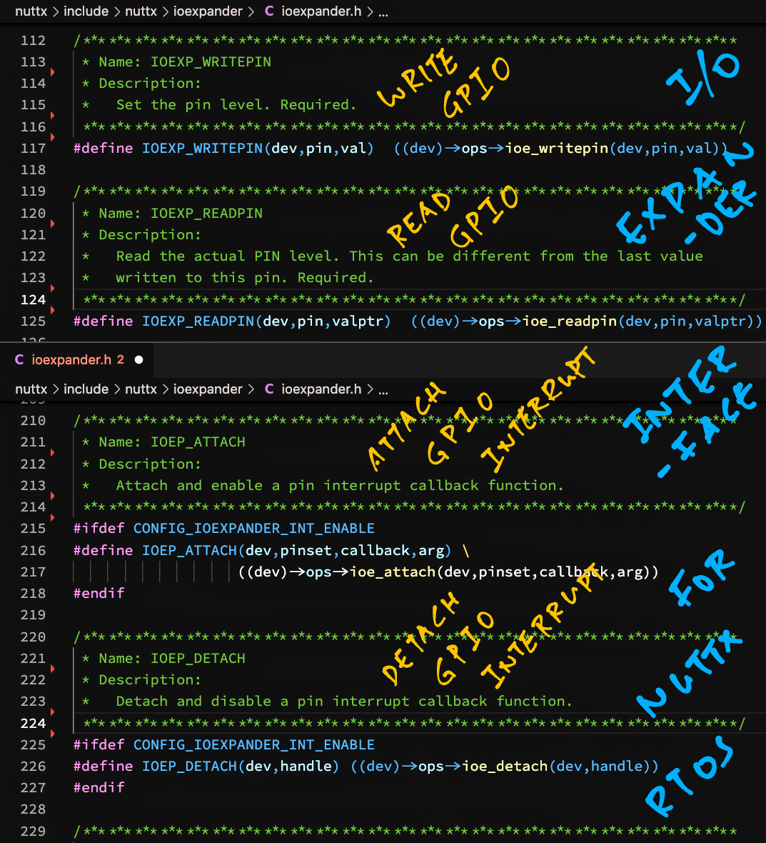
I/O Expanders will support reading and writing to GPIOs, also attaching and detaching Interrupt Callbacks. (Pic above)
Isn’t an I/O Expander Driver supposed to be Platform-Independent?
Yeah, we’re borrowing (misappropriating?) this NuttX Abstraction because it meets our needs for PineDio Stack.
Other RISC-V microcontrollers might also need a GPIO Expander… Like CH32V307, which has 80 GPIOs!
Great! How will we get started on GPIO Expander?
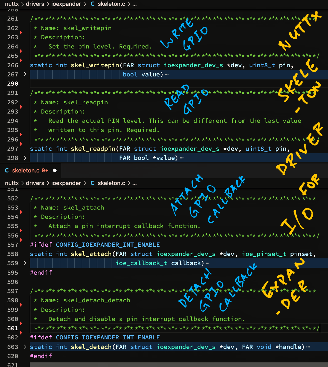
NuttX helpfully provides a Skeleton Driver for I/O Expander (pic below)…
Let’s flesh out the Skeleton Driver for our GPIO Expander.
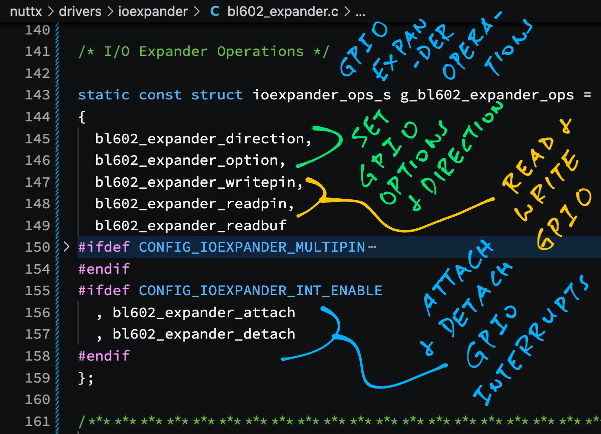
Our GPIO Expander supports these GPIO Operations…
Set GPIO Direction
(Input or Output)
Set GPIO Interrupt Options
(Trigger by Rising or Falling Edge)
Read a GPIO Input
Write to a GPIO Output
Attach / Detach a GPIO Interrupt Callback
We define the GPIO Operations like so: bl602_expander.c
//  GPIO Expander Operations
static const struct ioexpander_ops_s g_bl602_expander_ops = {
  bl602_expander_direction,  //  Set GPIO Direction
  bl602_expander_option,     //  Set GPIO Interrupt Options
  bl602_expander_writepin,   //  Write to GPIO Output
  bl602_expander_readpin,    //  Read from GPIO Input
  bl602_expander_readbuf,    //  (Read Buffer Not Implemented)
  ...
  bl602_expander_attach,     //  Attach GPIO Interrupt Callback
  bl602_expander_detach      //  Detach GPIO Interrupt Callback
};
The implementation of the GPIO Operations is explained in the Appendix…
Existing NuttX Drivers call bl602_gpioread and bl602_gpiowrite to read and write BL602 GPIOs. Will they still work?
Yep the BL602 GPIO Functions like bl602_gpioread and bl602_gpiowrite will work fine with GPIO Expander.
The NuttX GPIO Functions like open() and ioctl() will also work with GPIO Expander.
(That’s because they call the GPIO Lower Half Driver, which is integrated with our GPIO Expander)
Let’s look at GPIO Interrupts, which are more complicated…
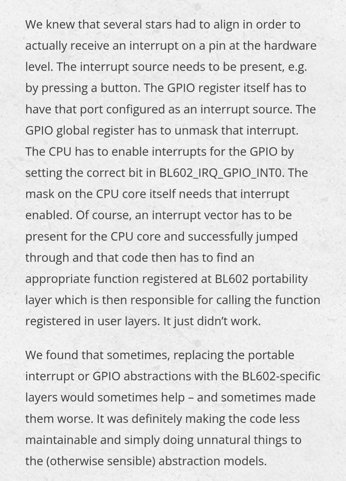
BL602 EVB works OK with GPIO Interrupts?
As noted (eloquently) by Robert Lipe, it’s difficult to attach a GPIO Interrupt Callback with BL602 EVB…
Let’s find out why…
(Perhaps our stars were misaligned 😂)
Anything peculiar about GPIO Interrupts on BL602 and BL604?
GPIO Interrupt Handling gets tricky for BL602 and BL604…
All GPIO Interrupts are multiplexed into One Single GPIO IRQ!
(BL602_IRQ_GPIO_INT0 is the common GPIO IRQ)
BL602 EVB demultiplexes the GPIO IRQ and calls the GPIO Interrupt Callbacks.
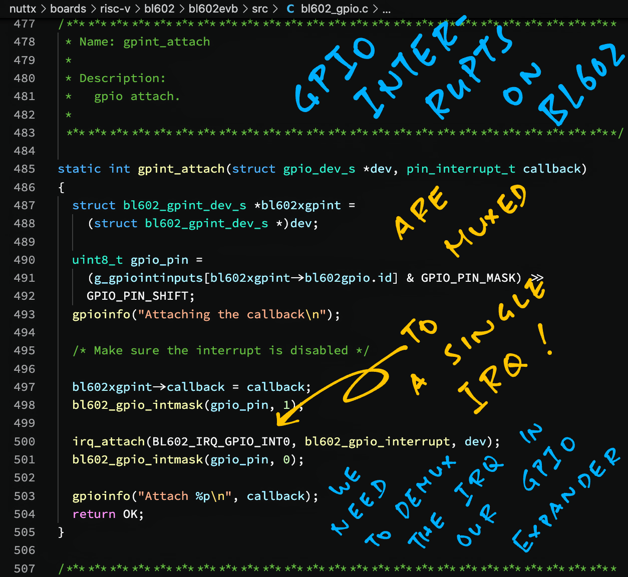
So we call BL602 EVB to attach our own GPIO Interrupt Callback?
Sadly we can’t. BL602 EVB doesn’t expose a Public Function that we may call to attach our Interrupt Callback.
(gpint_attach is a Private Function, as shown above)
We could call ioctl(), but that would be extremely awkward in the Kernel Space.
Which means we need to implement this in our GPIO Expander?
Exactly! Our GPIO Expander shall take over these duties from BL602 EVB…
Handle the GPIO IRQ Interrupt
Demultiplex the IRQ
Call the right GPIO Interrupt Callback
More about the implementation in a moment. Let’s talk about calling the GPIO Expander…
How do we attach a GPIO Interrupt Callback?
Because GPIO Expander implements the I/O Expander Interface, we may call IOEP_ATTACH to attach an Interrupt Callback.
Let’s attach an Interrupt Callback that will be called when we press the Push Button (GPIO 12) on PineDio Stack: bl602_bringup.c
#include <nuttx/ioexpander/gpio.h>
#include <nuttx/ioexpander/bl602_expander.h>
...
//  Get the Push Button Pinset and GPIO Pin Number
gpio_pinset_t pinset = BOARD_BUTTON_INT;
uint8_t gpio_pin = (pinset & GPIO_PIN_MASK) >> GPIO_PIN_SHIFT;(BOARD_BUTTON_INT is defined in board.h)
First we get the GPIO Pin Number for the Push Button.
Then we configure our GPIO Expander to trigger the GPIO Interrupt on the Falling Edge (High to Low)…
//  Configure GPIO interrupt to be triggered on falling edge
DEBUGASSERT(bl602_expander != NULL);
IOEXP_SETOPTION(
  bl602_expander,  //  BL602 GPIO Expander
  gpio_pin,        //  GPIO Pin
  IOEXPANDER_OPTION_INTCFG,            //  Configure interrupt trigger
  (FAR void *) IOEXPANDER_VAL_FALLING  //  Trigger on falling edge
);(IOEXP_SETOPTION comes from the I/O Expander)
Finally we call GPIO Expander to attach our Interrupt Callback…
//  Attach our GPIO interrupt callback
void *handle = IOEP_ATTACH(
  bl602_expander,                //  BL602 GPIO Expander
  (ioe_pinset_t) 1 << gpio_pin,  //  GPIO Pin converted to Pinset
  button_isr_handler,            //  GPIO Interrupt Callback
  NULL                           //  TODO: Set the callback argument
);
DEBUGASSERT(handle != NULL);(IOEP_ATTACH comes from the I/O Expander)
The Interrupt Callback is defined as…
//  Our GPIO Interrupt Callback
static int button_isr_handler(FAR struct ioexpander_dev_s *dev, ioe_pinset_t pinset, FAR void *arg) {
  gpioinfo("Button Pressed\n");
  return 0;
}Note that the Interrupt Callback runs in the BL602 Interrupt Context.
Be careful!
Another way to test the Push Button Interrupt is to use the GPIO Command.
(This only works if we don’t call IOEP_ATTACH to attach the Interrupt Callback)
Enter this in the NuttX Shell…
gpio -t 8 -w 1 /dev/gpio12Which says…
Configure the GPIO for Rising Edge Interrupt
And wait 5 seconds for Signal 1
Quickly press the Push Button on PineDio Stack. We should see…
Interrupt pin: Value=1
Verify: Value=1If we don’t press the button within 5 seconds, the GPIO Command reports an Interrupt Timeout…
Interrupt pin: Value=1
[Five second timeout with no signal]Who else is calling GPIO Expander to handle interrupts?
The CST816S Driver for PineDio Stack’s Touch Panel calls GPIO Expander to attach an Interrupt Callback (that’s called when the screen is touched)…
The Semtech SX1262 LoRa Transceiver on PineDio Stack triggers a GPIO Interrupt (on pin DIO1) when a LoRa packet is transmitted or received…
This code calls ioctl() in the User Space (instead of Kernel Space), so it works OK with GPIO Expander without modification.
(That’s because ioctl() calls the GPIO Lower Half Driver, which is integrated with our GPIO Expander)
Here’s how we load our GPIO Expander at startup: bl602_bringup.c
#ifdef CONFIG_IOEXPANDER_BL602_EXPANDER
#include <nuttx/ioexpander/gpio.h>
#include <nuttx/ioexpander/bl602_expander.h>

//  Global Instance of GPIO Expander
FAR struct ioexpander_dev_s *bl602_expander = NULL;
#endif  //  CONFIG_IOEXPANDER_BL602_EXPANDER
...
int bl602_bringup(void) {
  ...
//  Existing Code
#if defined(CONFIG_DEV_GPIO) && !defined(CONFIG_GPIO_LOWER_HALF)
  ret = bl602_gpio_initialize();
  if (ret < 0) {
    syslog(LOG_ERR, "Failed to initialize GPIO Driver: %d\n", ret);
    return ret;
  }
#endif

//  New Code
#ifdef CONFIG_IOEXPANDER_BL602_EXPANDER
  //  Must load BL602 GPIO Expander before other drivers
  bl602_expander = bl602_expander_initialize(
    bl602_gpio_inputs,     sizeof(bl602_gpio_inputs) / sizeof(bl602_gpio_inputs[0]),
    bl602_gpio_outputs,    sizeof(bl602_gpio_outputs) / sizeof(bl602_gpio_outputs[0]),
    bl602_gpio_interrupts, sizeof(bl602_gpio_interrupts) / sizeof(bl602_gpio_interrupts[0]),
    bl602_other_pins,      sizeof(bl602_other_pins) / sizeof(bl602_other_pins[0]));
  if (bl602_expander == NULL) {
    syslog(LOG_ERR, "Failed to initialize GPIO Expander\n");
    return -ENOMEM;
  }
#endif  //  CONFIG_IOEXPANDER_BL602_EXPANDER
(We’ll talk about bl602_gpio_* in the next chapter)
We must load the GPIO Expander before other drivers (like CST816S Touch Panel), because GPIO Expander provides GPIO functions for the drivers.
We need to disable the BL602 EVB GPIO Driver, because GPIO Expander needs the GPIO Lower Half Driver (which can’t coexist with BL602 EVB GPIO)…
//  Added CONFIG_GPIO_LOWER_HALF below
#if defined(CONFIG_DEV_GPIO) && !defined(CONFIG_GPIO_LOWER_HALF)
ret = bl602_gpio_initialize();Check the following in menuconfig…
Enable “BL602 GPIO Expander” under “Device Drivers → IO Expander/GPIO Support → Enable IO Expander Support”
Set “Number Of Pins” to 23
Enable “GPIO Lower Half”
Managing 23 GPIOs sounds mighty challenging?
Indeed! Tracking all 23 GPIOs used by PineDio Stack can get challenging… We might reuse the GPIOs by mistake!
Thankfully our GPIO Expander can help: It validates the GPIOs at startup.
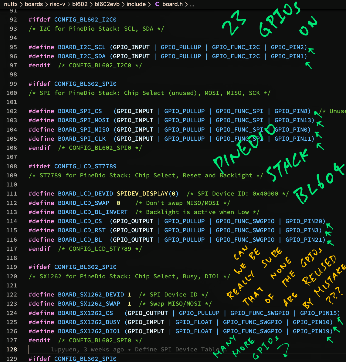
Here are the GPIOs currently defined for PineDio Stack (more to come)…
At startup, GPIO Expander verifies that the GPIO, UART, I2C, SPI and PWM Ports don’t reuse the same GPIO.
If a GPIO is reused like so…
//  SPI CLK: GPIO 11
#define BOARD_SPI_CLK    (GPIO_PIN11 | GPIO_INPUT | GPIO_PULLUP | GPIO_FUNC_SPI)
...
//  Push Button Interrupt: Also GPIO 11 (Oops!)
#define BOARD_BUTTON_INT (GPIO_PIN11 | GPIO_INPUT | GPIO_FLOAT | GPIO_FUNC_SWGPIO)
Then GPIO Expander will halt with an error at startup…
bl602_expander_initialize: ERROR:
GPIO pin 11 is already in use
Awesome! How do we enable this GPIO Validation?
To enable GPIO Validation, we add all GPIOs to the arrays bl602_gpio_inputs, bl602_gpio_outputs, bl602_gpio_interrupts and bl602_other_pins: bl602_bringup.c
#ifdef CONFIG_IOEXPANDER_BL602_EXPANDER
//  GPIO Input Pins for BL602 GPIO Expander
static const gpio_pinset_t bl602_gpio_inputs[] =
{
#ifdef BOARD_SX1262_BUSY
  BOARD_SX1262_BUSY,
#endif  //  BOARD_SX1262_BUSY
//  Omitted: Other GPIO Input Pins
...
};

//  GPIO Output Pins for BL602 GPIO Expander
static const gpio_pinset_t bl602_gpio_outputs[] =
{
#ifdef BOARD_LCD_CS
  BOARD_LCD_CS,
#endif  //  BOARD_LCD_CS
//  Omitted: Other GPIO Output Pins
...
};

//  GPIO Interrupt Pins for BL602 GPIO Expander
static const gpio_pinset_t bl602_gpio_interrupts[] =
{
#ifdef BOARD_TOUCH_INT
  BOARD_TOUCH_INT,
#endif  //  BOARD_TOUCH_INT
//  Omitted: Other GPIO Interrupt Pins
...
};

//  Other Pins for BL602 GPIO Expander (For Validation Only)
static const gpio_pinset_t bl602_other_pins[] =
{
#ifdef BOARD_UART_0_RX_PIN
  BOARD_UART_0_RX_PIN,
#endif  //  BOARD_UART_0_RX_PIN
//  Omitted: Other UART, I2C, SPI and PWM Pins
...
};
#endif  //  CONFIG_IOEXPANDER_BL602_EXPANDER
At startup, we pass the pins to GPIO Expander during initialisation…
//  Initialise GPIO Expander at startup
bl602_expander = bl602_expander_initialize(
  //  BL602 Pinsets for GPIO Inputs and number of pins
  bl602_gpio_inputs,
  sizeof(bl602_gpio_inputs) / sizeof(bl602_gpio_inputs[0]),
  //  BL602 Pinsets for GPIO Outputs and number of pins
  bl602_gpio_outputs,
  sizeof(bl602_gpio_outputs) / sizeof(bl602_gpio_outputs[0]),
  //  BL602 Pinsets for GPIO Interrupts and number of pins
  bl602_gpio_interrupts,
  sizeof(bl602_gpio_interrupts) / sizeof(bl602_gpio_interrupts[0]),
  //  BL602 Pinsets for Other Pins (UART, I2C, SPI, PWM) and number of pins
  bl602_other_pins,
  sizeof(bl602_other_pins) / sizeof(bl602_other_pins[0]));
GPIO Expander verifies that the GPIOs are not reused…
FAR struct ioexpander_dev_s *bl602_expander_initialize(
  //  BL602 Pinsets for GPIO Inputs and number of pins
  const gpio_pinset_t *gpio_inputs,     uint8_t gpio_input_count,
  //  BL602 Pinsets for GPIO Outputs and number of pins
  const gpio_pinset_t *gpio_outputs,    uint8_t gpio_output_count,
  //  BL602 Pinsets for GPIO Interrupts and number of pins
  const gpio_pinset_t *gpio_interrupts, uint8_t gpio_interrupt_count,
  //  BL602 Pinsets for Other Pins (UART, I2C, SPI, PWM) and number of pins
  const gpio_pinset_t *other_pins,      uint8_t other_pin_count) {
  ...
  //  Mark the GPIOs in use. CONFIG_IOEXPANDER_NPINS is 23
  bool gpio_is_used[CONFIG_IOEXPANDER_NPINS];
  memset(gpio_is_used, 0, sizeof(gpio_is_used));

  //  Validate the GPIO Inputs
  for (i = 0; i < gpio_input_count; i++) {
    //  Get GPIO Pinset and GPIO Pin Number
    gpio_pinset_t pinset = gpio_inputs[i];
    uint8_t gpio_pin = (pinset & GPIO_PIN_MASK) >> GPIO_PIN_SHIFT;

    //  Check that the GPIO is not in use
    if (gpio_is_used[gpio_pin]) {
      gpioerr("ERROR: GPIO pin %d is already in use\n", gpio_pin);
      return NULL;
    }
    gpio_is_used[gpio_pin] = true;
  }

// Omitted: Validate the GPIO Outputs, GPIO Interrupts and Other PinsLet’s talk about something else we might validate at startup: Pin Functions.
(More about GPIO Expander initialisation)
TODO: Validate that GPIO Inputs have GPIO_INPUT, GPIO Outputs have GPIO_OUTPUT, GPIO Interrupts have GPIO_INPUT. All GPIO Inputs / Outputs / Interrupts must have GPIO_FUNC_SWGPIO. All Other Pins must have either GPIO_FUNC_UART, GPIO_FUNC_I2C, GPIO_FUNC_SPI or GPIO_FUNC_PWM.
We’re selecting a GPIO Pin for a UART / I2C / SPI / PWM Port…
Which pin can we use?
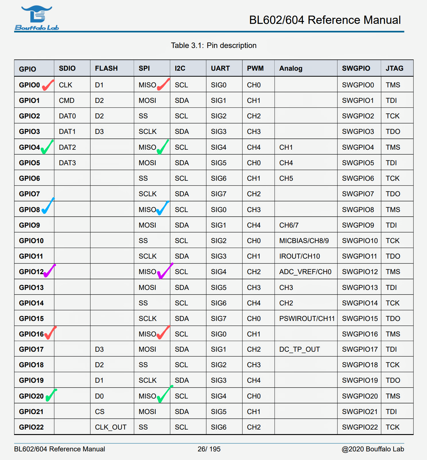
The Pin Functions for each GPIO Pin are documented here…
In NuttX, we set the Pin Definitions at…
Let’s say we’re selecting a pin for SPI MISO?
According to the pic above, SPI MISO must be either GPIO 0, 4, 8, 12, 16 or 20.
(Beware: MISO and MOSI are swapped)
So this MISO Pin Definition is OK…
//  GPIO 0 for MISO is OK
#define BOARD_SPI_MISO (GPIO_PIN0 | GPIO_INPUT | GPIO_PULLUP | GPIO_FUNC_SPI)But this MISO Pin Definition is no-no…
//  GPIO 3 for MISO is NOT OK (Oops!)
#define BOARD_SPI_MISO (GPIO_PIN3 | GPIO_INPUT | GPIO_PULLUP | GPIO_FUNC_SPI)
8 possible pins for MISO? Wow that’s a lot of choices!
BL602 / BL604 gives us incredible flexibility in selecting the pins…
But we might pick the wrong pin by mistake!
(Looks like an extreme form of STM32’s Alternate Pin Functions)
Is there a way to prevent such mistakes?
We have some ideas for validating the Pin Functions at compile-time or at startup…
But for now, be very careful when selecting pins!
How shall we test our GPIO Expander on PineDio Stack?
We’ll test with 3 features that are shipped with PineDio Stack…
CST816S Touch Panel
(Which triggers a GPIO Interrupt when touched)
Push Button
(Which also triggers a GPIO Interrupt when pushed)
LoRaWAN with Semtech SX1262 Transceiver
(Which uses GPIO Input, Output and Interrupt)
Follow these steps to build, flash and run NuttX on PineDio Stack…
In the NuttX Shell, enter this command to list the NuttX Devices…
ls /devWe should see more than 3 GPIOs…
/dev:
 gpio10
 gpio12
 gpio14
 gpio15
 gpio19
 gpio20
 gpio21
 gpio3
gpio9Which means that our GPIO Expander is active.
We’re ready to test GPIO Expander!
At startup, we should see…
gpio_pin_register: Registering /dev/gpio9
bl602_expander_option: Falling edge: pin=9
bl602_expander_attach: Attach callback for gpio=9
cst816s_register: Driver registeredWhich says that our NuttX Driver for CST816S Touch Panel has called GPIO Expander to configure GPIO 9 for Falling Edge Trigger. (High to Low)
And the driver has called GPIO Expander to attach an Interrupt Callback for GPIO 9.
In the NuttX Shell, enter this command to start the LVGL Test App…
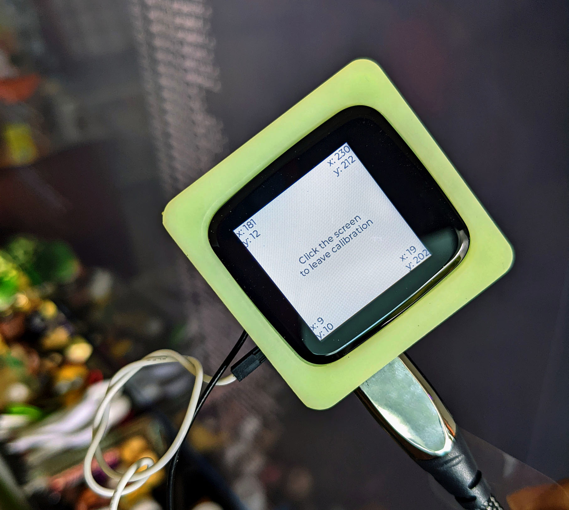
lvgltestWhen prompted to calibrate the screen, tap the 4 corners of the screen. (Pic above)
We should see…
bl602_expander_interrupt: Interrupt!
bl602_expander_interrupt: Call gpio=9
cst816s_get_touch_data: DOWN: id=0, touch=0, x=190, y=18
cst816s_get_touch_data:   id:      0
cst816s_get_touch_data:   flags:   19
cst816s_get_touch_data:   x:       190
cst816s_get_touch_data: y: 18Which says that our Interrupt Callback for GPIO 9 has been triggered.
GPIO Expander handles the interrupt and calls the Touch Panel Driver. (Which fetches the Touch Data later)
Yep GPIO Expander works great with PineDio Stack’s Touch Panel!
(More about the LVGL Test App)
(More about the CST816S Touch Panel)
Earlier we spoke about running the GPIO Command to test the Push Button Interrupt (GPIO 12)…
(Assuming that we don’t call IOEP_ATTACH in NuttX)
The GPIO Command starts by calling GPIO Expander to configure GPIO 12 for Rising Edge Trigger. (Low to High)
nsh> gpio -t 8 -w 1 /dev/gpio12
bl602_expander_option: Rising edge: pin=12
bl602_expander_readpin: pin=12, value=1
Interrupt pin: Value=1
bl602_expander_attach: Attach callback for gpio=12Then it calls GPIO Expander to read GPIO 12. And attach an Interrupt Callback for GPIO 12.
When we press the Push Button, GPIO Expander handles the interrupt…
bl602_expander_interrupt: Interrupt!
bl602_expander_interrupt: Call gpio=12
And calls the Interrupt Callback for GPIO 12.
Finally the GPIO Command calls GPIO Expander to detach the Interrupt Callback…
bl602_expander_detach: Detach callback for gpio=12
bl602_expander_readpin: pin=12, value=1
Verify: Value=1
And read the GPIO Input one last time.
LoRaWAN is the Ultimate Test for GPIO Expander. It depends on 3 GPIOs connected to the Semtech SX1262 LoRa Transceiver…
SX1262 BUSY at /dev/gpio10
GPIO Input that tells us whether SX1262 is busy
(BUSY is High when SX1262 is busy)
SX1262 Chip Select at /dev/gpio15
GPIO Output to select or deselect SX1262 on the SPI Bus
(Chip Select is Low when SX1262 is selected)
SX1262 DIO1 at /dev/gpio19
GPIO Interrupt for SX1262 to signal that a LoRa Packet has been transmitted or received
(DIO1 shifts from Low to High when that happens)
In the NuttX Shell, enter this command to start the LoRaWAN Test App…
lorawan_testOur LoRaWAN App calls GPIO Expander to attach an Interrupt Callback for GPIO 19…
init_gpio: change DIO1 to Trigger GPIO Interrupt on Rising Edge
###### =========== MLME-Request ============ ######
######               MLME_JOIN               ######
###### ===================================== ######And sends a Join LoRaWAN Network request to our LoRaWAN Gateway (ChipStack).
(Which calls GPIO Expander on GPIO 10 to check if the LoRa Transceiver is busy, and GPIO 15 to activate the SPI Bus)
After sending the request, the LoRa Transceiver triggers an interrupt on GPIO 19…
DIO1 add event
RadioOnDioIrq
RadioIrqProcess
IRQ_TX_DONE
Which is handled by GPIO Expander and our LoRaWAN App.
Eventually our app receives the Join Network Response from our LoRaWAN Gateway…
###### =========== MLME-Confirm ============ ######
STATUS      : OK
###### ===========   JOINED     ============ ######
OTAA
DevAddr     : 014C9548
DATA RATE   : DR_2
And sends a LoRaWAN Data Packet (“Hi NuttX”) to the gateway…
###### =========== MCPS-Confirm ============ ######
STATUS      : OK
###### =====   UPLINK FRAME        1   ===== ######
CLASS       : A
TX PORT     : 1
TX DATA     : UNCONFIRMED
48 69 20 4E 75 74 74 58 00
DATA RATE   : DR_3
U/L FREQ    : 923400000
TX POWER    : 0
CHANNEL MASK: 0003
The data packet appears on our LoRaWAN Gateway.
Congratulations we have successfully tested GPIO Input, Output and Interrupt with GPIO Expander!
(More about the LoRaWAN Test App)
Now that we’ve fixed the GPIO problem with GPIO Expander, I hope it’s a lot easier to create NuttX Drivers and Apps on PineDio Stack.
Lemme know what you’re building with PineDio Stack!
Many Thanks to my GitHub Sponsors for supporting my work! This article wouldn’t have been possible without your support.
Got a question, comment or suggestion? Create an Issue or submit a Pull Request here…
lupyuen.github.io/src/expander.md
In NuttX, we set the Pin Definitions at…
BL602 / BL604 gives us incredible flexibility in selecting the GPIO Pins for the UART, I2C, SPI and PWM Ports…
(8 possible pins for SPI MISO! Pic above)
But we might pick the wrong pin by mistake!
For example, this MISO Pin Definition is OK…
//  GPIO 0 for MISO is OK
#define BOARD_SPI_MISO (GPIO_PIN0 | GPIO_INPUT | GPIO_PULLUP | GPIO_FUNC_SPI)But this MISO Pin Definition is no-no…
//  GPIO 3 for MISO is NOT OK (Oops!)
#define BOARD_SPI_MISO (GPIO_PIN3 | GPIO_INPUT | GPIO_PULLUP | GPIO_FUNC_SPI)
Is there a way to prevent such mistakes?
We have some ideas for validating the Pin Functions at compile-time or at startup…
Can we validate the Pin Functions at compile-time?
Possibly. We can enumerate all valid combinations of Pin Functions and Pin Numbers…
//  SPI MISO can be either GPIO 0, 4, 8, 12, 16 or 20
#define SPI_MISO_PIN0  (GPIO_PIN0  | GPIO_INPUT | GPIO_PULLUP | GPIO_FUNC_SPI)
#define SPI_MISO_PIN4  (GPIO_PIN4  | GPIO_INPUT | GPIO_PULLUP | GPIO_FUNC_SPI)
#define SPI_MISO_PIN8  (GPIO_PIN8  | GPIO_INPUT | GPIO_PULLUP | GPIO_FUNC_SPI)
#define SPI_MISO_PIN12 (GPIO_PIN12 | GPIO_INPUT | GPIO_PULLUP | GPIO_FUNC_SPI)
#define SPI_MISO_PIN16 (GPIO_PIN16 | GPIO_INPUT | GPIO_PULLUP | GPIO_FUNC_SPI)
#define SPI_MISO_PIN20 (GPIO_PIN20 | GPIO_INPUT | GPIO_PULLUP | GPIO_FUNC_SPI)
And we select the desired combination for each pin…
//  Select GPIO 0 as MISO
#define BOARD_SPI_MISO SPI_MISO_PIN0
What happens if we pick the wrong pin?
This is disallowed…
//  Select GPIO 3 as MISO... Not possible!
#define BOARD_SPI_MISO SPI_MISO_PIN3
Because SPI_MISO_PIN3 doesn’t exist!
But to check whether the Pin Numbers are unique, we would still need GPIO Expander to do this at runtime.
Shouldn’t the pins be defined in Kconfig / menuconfig?
Perhaps. NuttX on ESP32 uses Kconfig / menuconfig to define the pins. (See this)
Then we would need GPIO Expander to validate the Pin Functions at runtime.
@Ralim has an interesting suggestion…
If each pin can only be used once, could we flip the arrignment matrix and instead have it always have an entry for each pin, which is either a selected value or hi-z by default; then use kconfig rules to prevent collisions ?
Which begs the question: Shouldn’t we do the same for NuttX on ESP32? What about other NuttX platforms? 🤔
What about validating the pins at startup?
During initialisation, GPIO Expander could validate that the UART / I2C / SPI / PWM Pin Functions are correctly assigned to the GPIO Pin Numbers.
So it would verify that SPI MISO (from the Pin Definitions) must be either GPIO 0, 4, 8, 12, 16 or 20.
Any other GPIO Pin for SPI MISO will be disallowed by our GPIO Expander. (And fail at startup)
But the Pin Definitions only tell us the Function Group (like SPI), not the specific Pin Function (like MISO)?
Yeah we might have to make the Pin Functions position-dependent. So SPI Pins will always be listed in this sequence: CS, MOSI, MISO, then CLK.
Here’s how bl602_other_pins might look in bl602_bringup.c
/* Other Pins for BL602 GPIO Expander (For Validation Only) */

static const gpio_pinset_t bl602_other_pins[] =
{
#ifdef BOARD_UART_0_RX_PIN
  RX_TX
  (
    BOARD_UART_0_RX_PIN,
    BOARD_UART_0_TX_PIN
  ),
#endif  /* BOARD_UART_0_RX_PIN */

#ifdef BOARD_UART_1_RX_PIN
  RX_TX
  (
    BOARD_UART_1_RX_PIN,
    BOARD_UART_1_TX_PIN
  ),
#endif  /* BOARD_UART_1_RX_PIN */

#ifdef BOARD_PWM_CH0_PIN
  CH(
    BOARD_PWM_CH0_PIN
  ),
#endif  /* BOARD_PWM_CH0_PIN */
...
#ifdef BOARD_I2C_SCL
  SCL_SDA
  (
    BOARD_I2C_SCL,
    BOARD_I2C_SDA
  ),
#endif  /* BOARD_I2C_SCL */

#ifdef BOARD_SPI_CS
  CS_MOSI_MISO_CLK
  (
    BOARD_SPI_CS,
    BOARD_SPI_MOSI,
    BOARD_SPI_MISO,
    BOARD_SPI_CLK
  ),
#endif  /* BOARD_SPI_CS */
};
The macros are simple passthroughs…
#define CH(ch)            ch
#define RX_TX(rx, tx)     rx,  tx
#define SCL_SDA(scl, sda) scl, sda
#define CS_MOSI_MISO_CLK(cs, mosi, miso, clk) cs, mosi, miso, clk
At startup, GPIO Expander iterates through the pins and discovers that BOARD_SPI_MISO is the third pin (MISO) of the SPI Function Group. So it verifies that it’s either GPIO 0, 4, 8, 12, 16 or 20.
Which is your preferred way to validate the Pin Functions? Lemme know! 🙏
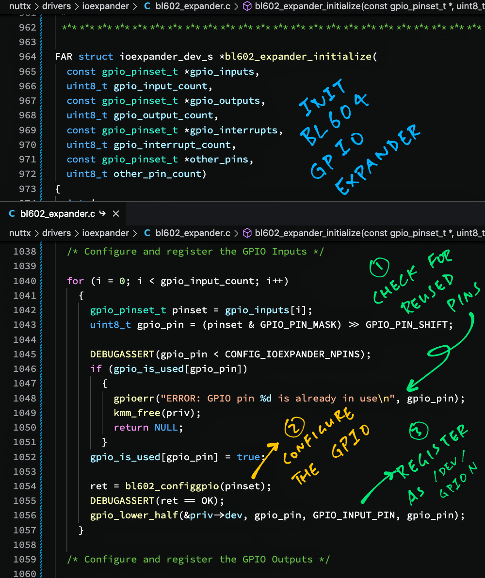
At startup, our GPIO Expander does the following initialisation…
Attach the GPIO Expander Interrupt Handler to the GPIO IRQ
Configure the GPIO Input, Output and Interrupt Pins by calling bl602_configgpio
Register the GPIOs as “/dev/gpioN” by calling gpio_lower_half
Validate the GPIOs and prevent reuse of GPIOs
Here’s the code: bl602_expander.c
//  Initialise the BL602 GPIO Expander
FAR struct ioexpander_dev_s *bl602_expander_initialize(
  //  BL602 Pinsets for GPIO Input and number of pins
  const gpio_pinset_t *gpio_inputs,
  uint8_t gpio_input_count,
  //  BL602 Pinsets for GPIO Output and number of pins
  const gpio_pinset_t *gpio_outputs,
  uint8_t gpio_output_count,
  //  BL602 Pinsets for GPIO Interrupts and number of pins
  const gpio_pinset_t *gpio_interrupts,
  uint8_t gpio_interrupt_count,
  //  BL602 Pinsets for Other Pins (UART, I2C, SPI, UART) and number of pins
  const gpio_pinset_t *other_pins,
  uint8_t other_pin_count)
{
  DEBUGASSERT(gpio_input_count + gpio_output_count + gpio_interrupt_count +
    other_pin_count <= CONFIG_IOEXPANDER_NPINS);

  /* Use the one-and-only I/O Expander driver instance */
  FAR struct bl602_expander_dev_s *priv = &g_bl602_expander_dev;

  /* Initialize the device state structure */
  priv->dev.ops = &g_bl602_expander_ops;
  nxsem_init(&priv->exclsem, 0, 1);
The function begins by populating the Device State for GPIO Expander.
(Including the Semaphore that will lock the GPIO Expander)
Next it disables the Specific GPIO Interrupts for all GPIOs, and attaches the GPIO Expander Interrupt Handler to the GPIO IRQ…
  /* Disable GPIO interrupts */
  int ret = bl602_expander_irq_enable(false);
  if (ret < 0) { return NULL; }

  /* Disable interrupts for all GPIO Pins. CONFIG_IOEXPANDER_NPINS is 23 */
  for (uint8_t pin = 0; pin < CONFIG_IOEXPANDER_NPINS; pin++)
    {
      bl602_expander_intmask(pin, 1);
    }

  /* Attach the I/O expander interrupt handler and enable interrupts */
  irq_attach(BL602_IRQ_GPIO_INT0, bl602_expander_interrupt, priv);

  ret = bl602_expander_irq_enable(true);
if (ret < 0) { return NULL; }(bl602_expander_interrupt is explained here)
(bl602_expander_intmask is defined here)
(bl602_expander_irq_enable is defined here)
(irq_attach comes from the BL602 IRQ Driver)
(Specific GPIO Interrupts are enabled later when we attach an Interrupt Callback to the specific GPIO)
To prevent reuse of GPIOs, we prepare the array that will mark the used GPIOs…
  /* Mark the GPIOs in use. CONFIG_IOEXPANDER_NPINS is 23 */
  bool gpio_is_used[CONFIG_IOEXPANDER_NPINS];
  memset(gpio_is_used, 0, sizeof(gpio_is_used));
Now we handle the GPIO Inputs.
Given the BL602 Pinset (from the Pin Definition), we call bl602_configgpio to configure each GPIO Input…
  /* Configure and register the GPIO Inputs */
  for (int i = 0; i < gpio_input_count; i++)
    {
      gpio_pinset_t pinset = gpio_inputs[i];
      uint8_t gpio_pin = (pinset & GPIO_PIN_MASK) >> GPIO_PIN_SHIFT;

      DEBUGASSERT(gpio_pin < CONFIG_IOEXPANDER_NPINS);
      if (gpio_is_used[gpio_pin])
        {
          gpioerr("ERROR: GPIO pin %d is already in use\n", gpio_pin);
          return NULL;
        }
      gpio_is_used[gpio_pin] = true;

      ret = bl602_configgpio(pinset);
      DEBUGASSERT(ret == OK);
      gpio_lower_half(&priv->dev, gpio_pin, GPIO_INPUT_PIN, gpio_pin);
    }
And we call gpio_lower_half to register the GPIO Input as “/dev/gpioN”.
(N is the GPIO Pin Number)
We quit if the GPIO is already in use.
We do the same for GPIO Outputs…
  /* Configure and register the GPIO Outputs */
  for (i = 0; i < gpio_output_count; i++)
    {
      gpio_pinset_t pinset = gpio_outputs[i];
      uint8_t gpio_pin = (pinset & GPIO_PIN_MASK) >> GPIO_PIN_SHIFT;

      DEBUGASSERT(gpio_pin < CONFIG_IOEXPANDER_NPINS);
      if (gpio_is_used[gpio_pin])
        {
          gpioerr("ERROR: GPIO pin %d is already in use\n", gpio_pin);
          return NULL;
        }
      gpio_is_used[gpio_pin] = true;

      ret = bl602_configgpio(pinset);
      DEBUGASSERT(ret == OK);
      gpio_lower_half(&priv->dev, gpio_pin, GPIO_OUTPUT_PIN, gpio_pin);
    }
And for GPIO Interrupts…
  /* Configure and register the GPIO Interrupts */
  for (i = 0; i < gpio_interrupt_count; i++)
    {
      gpio_pinset_t pinset = gpio_interrupts[i];
      uint8_t gpio_pin = (pinset & GPIO_PIN_MASK) >> GPIO_PIN_SHIFT;

      DEBUGASSERT(gpio_pin < CONFIG_IOEXPANDER_NPINS);
      if (gpio_is_used[gpio_pin])
        {
          gpioerr("ERROR: GPIO pin %d is already in use\n", gpio_pin);
          return NULL;
        }
      gpio_is_used[gpio_pin] = true;

      ret = bl602_configgpio(pinset);
      DEBUGASSERT(ret == OK);
      gpio_lower_half(&priv->dev, gpio_pin, GPIO_INTERRUPT_PIN, gpio_pin);
    }
For other GPIOs (UART, I2C, SPI, PWM) we check for reused GPIOs…
  /* Validate the other pins (I2C, SPI, etc) */
  for (i = 0; i < other_pin_count; i++)
    {
      gpio_pinset_t pinset = other_pins[i];
      uint8_t gpio_pin = (pinset & GPIO_PIN_MASK) >> GPIO_PIN_SHIFT;

      DEBUGASSERT(gpio_pin < CONFIG_IOEXPANDER_NPINS);
      if (gpio_is_used[gpio_pin])
        {
          gpioerr("ERROR: GPIO pin %d is already in use\n", gpio_pin);
          return NULL;
        }
      gpio_is_used[gpio_pin] = true;
    }

  /* TODO: Validate the Pin Functions (e.g. MISO vs MOSI) */
  return &priv->dev;
}
But we don’t call bl602_configgpio because that’s done by the UART / I2C / SPI / PWM Driver.
And we don’t call gpio_lower_half because the reserved GPIOs shouldn’t appear as “/dev/gpioN”.
That’s how we initialise our GPIO Expander at startup!
Our GPIO Expander exposes a Standard GPIO Function for setting the GPIO Direction (Input or Output).
However GPIO Expander doesn’t support GPIO Direction.
That’s because we configure GPIO Inputs and Outputs at startup. (See this)
Once the GPIOs are configured, we can’t change the GPIO Direction.
(In future we might allow this)
Here’s the function, which doesn’t do anything: bl602_expander.c
//  Set the direction of an GPIO Pin
static int bl602_expander_direction(
  FAR struct ioexpander_dev_s *dev,  //  GPIO Expander
  uint8_t pin,    //  Pin Number
  int direction)  //  Direction (Input or Output)
{
  gpioinfo("WARNING: Unimplemented direction: pin=%u, direction=%s\n",
           pin, (direction == IOEXPANDER_DIRECTION_IN) ? "IN" : "OUT");
  ...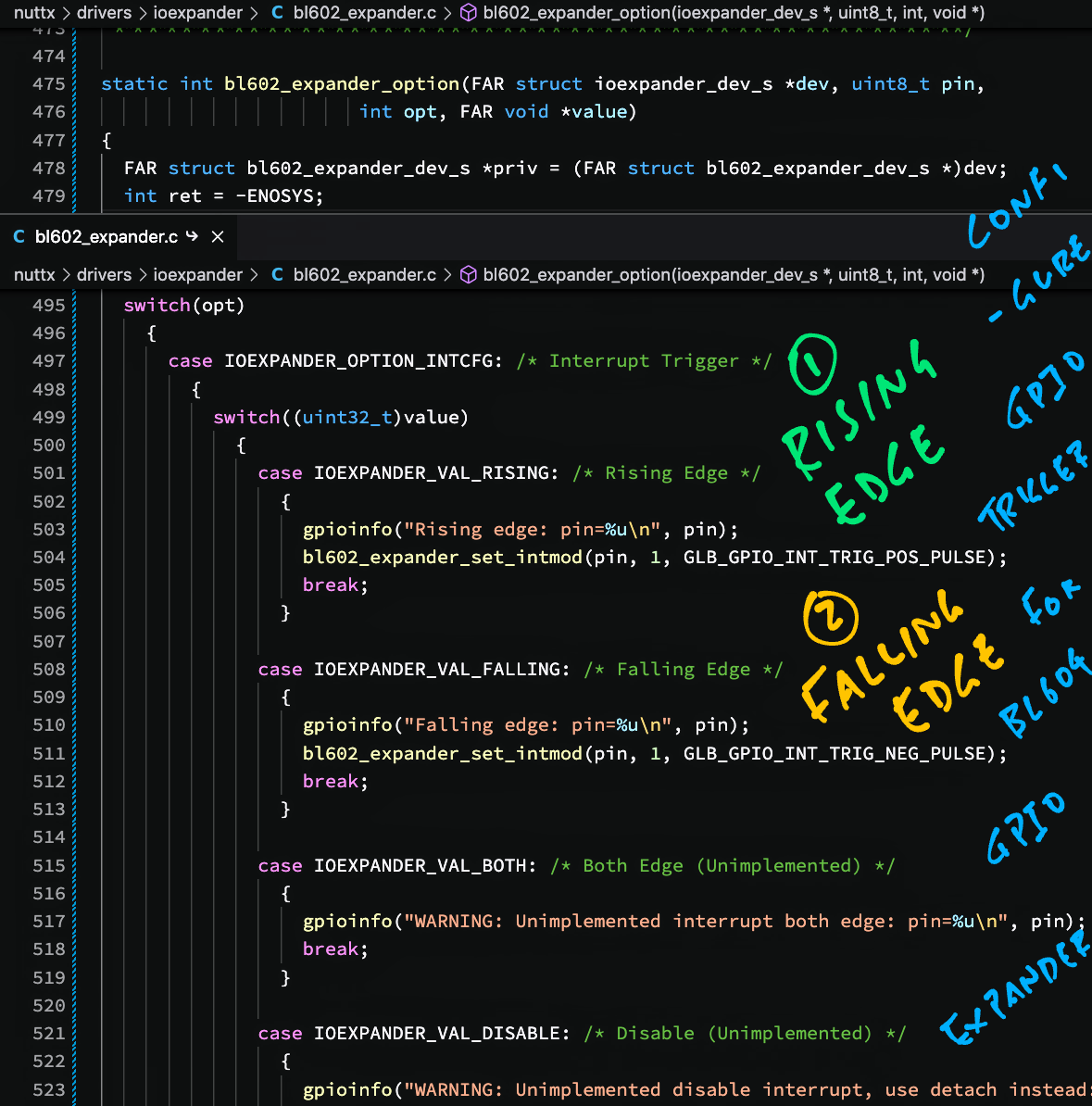
}For setting the GPIO Option, our GPIO Expander only supports 1 option: Interrupt Trigger.
The supported values for the option are…
Trigger by Rising Edge
Trigger by Falling Edge
All other options and values are ignored.
Note that we don’t support Disabling of Interrupts.
To disable a GPIO Interrupt, we detach the Interrupt Callback instead. (See this)
Here’s the implementation: bl602_expander.c
//  Set GPIO Options
static int bl602_expander_option(
  FAR struct ioexpander_dev_s *dev,  //  GPIO Expander
  uint8_t pin,      //  Pin Number
  int opt,          //  Option
  FAR void *value)  //  Value
{
  FAR struct bl602_expander_dev_s *priv = (FAR struct bl602_expander_dev_s *)dev;
  int ret = -ENOSYS;
  DEBUGASSERT(priv != NULL);

  /* Get exclusive access to the I/O Expander */
  ret = bl602_expander_lock(priv);
  if (ret < 0) { return ret; }

  /* Handle each option */
  switch(opt)
    {
      case IOEXPANDER_OPTION_INTCFG: /* Interrupt Trigger */
        {
          switch((uint32_t)value)
            {
              case IOEXPANDER_VAL_RISING: /* Rising Edge */
                {
                  bl602_expander_set_intmod(pin, 1, GLB_GPIO_INT_TRIG_POS_PULSE);
                  break;
                }

              case IOEXPANDER_VAL_FALLING: /* Falling Edge */
                {
                  bl602_expander_set_intmod(pin, 1, GLB_GPIO_INT_TRIG_NEG_PULSE);
                  break;
                }

              case IOEXPANDER_VAL_BOTH: /* Both Edge (Unimplemented) */
                {
                  gpioinfo("WARNING: Unimplemented interrupt both edge: pin=%u\n", pin);
                  break;
                }

              case IOEXPANDER_VAL_DISABLE: /* Disable (Unimplemented) */
                {
                  gpioinfo("WARNING: Unimplemented disable interrupt, use detach instead: pin=%u\n", pin);
                  break;
                }

              default: /* Unsupported Interrupt */
                {
                  gpioerr("ERROR: Unsupported interrupt: %d, pin=%u\n", value, pin);
                  ret = -EINVAL;
                  break;
                }
            }
          break;
        }

      default: /* Unsupported Option */
        {
          gpioerr("ERROR: Unsupported option: %d, pin=%u\n", opt, pin);
          ret = -ENOSYS;
        }
    }

  /* Unlock the I/O Expander */
  bl602_expander_unlock(priv);
  return ret;
}(bl602_expander_set_intmod is defined here)
Note that we copied bl602_expander_set_intmod from BL602 EVB GPIO Driver and fixed this bug…
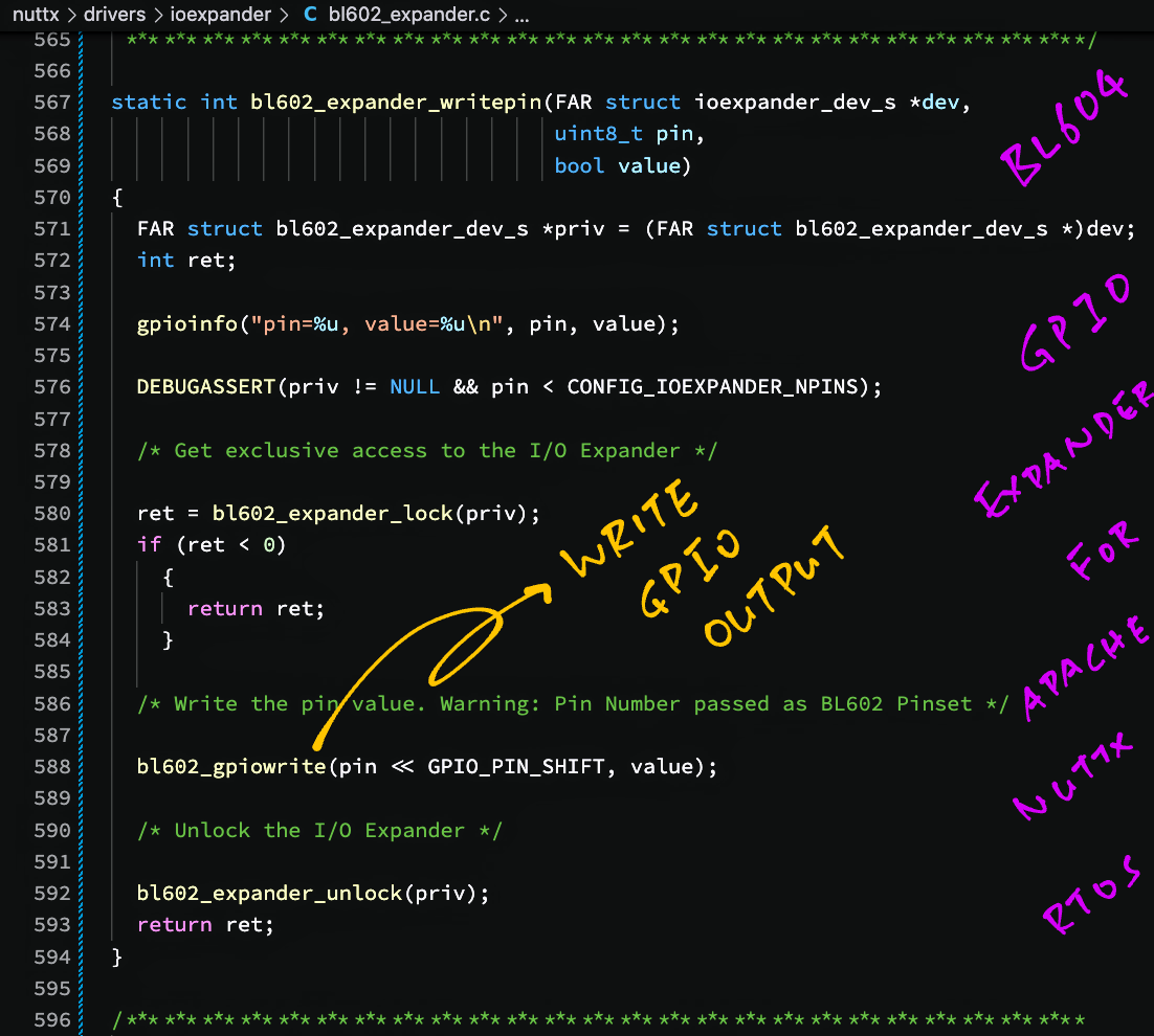
To write to a GPIO Output, our GPIO Expander calls the BL602 GPIO Driver: bl602_expander.c
//  Write to the GPIO Output Pin
static int bl602_expander_writepin(
  FAR struct ioexpander_dev_s *dev,  //  GPIO Expander
  uint8_t pin,  //  Pin Number
  bool value)   //  Output Value: 0 for Low, 1 for High
{
  FAR struct bl602_expander_dev_s *priv = (FAR struct bl602_expander_dev_s *)dev;
  int ret;
  gpioinfo("pin=%u, value=%u\n", pin, value);
  DEBUGASSERT(priv != NULL && pin < CONFIG_IOEXPANDER_NPINS);

  /* Get exclusive access to the I/O Expander */
  ret = bl602_expander_lock(priv);
  if (ret < 0) { return ret; }

  /* Write the pin value. Warning: Pin Number passed as BL602 Pinset */
  bl602_gpiowrite(pin << GPIO_PIN_SHIFT, value);

  /* Unlock the I/O Expander */
  bl602_expander_unlock(priv);
  return ret;
}(bl602_gpiowrite comes from the BL602 GPIO Driver)
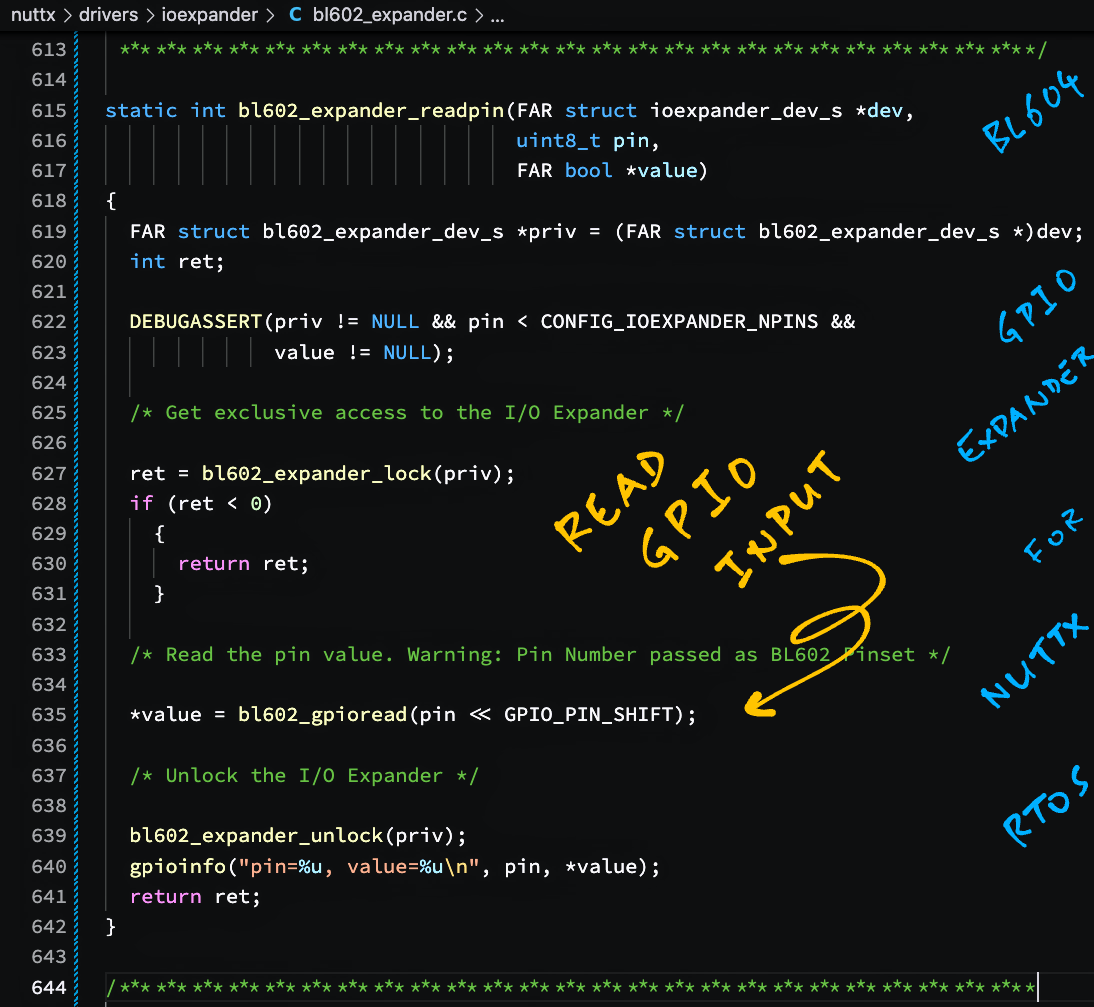
To read from a GPIO Input, our GPIO Expander also calls the BL602 GPIO Driver: bl602_expander.c
//  Read the GPIO Input Pin
static int bl602_expander_readpin(
  FAR struct ioexpander_dev_s *dev,  //  GPIO Expander
  uint8_t pin,      //  Pin Number
  FAR bool *value)  //  Returned Value: 0 for Low, 1 for High
{
  FAR struct bl602_expander_dev_s *priv = (FAR struct bl602_expander_dev_s *)dev;
  int ret;
  DEBUGASSERT(priv != NULL && pin < CONFIG_IOEXPANDER_NPINS &&
              value != NULL);

  /* Get exclusive access to the I/O Expander */
  ret = bl602_expander_lock(priv);
  if (ret < 0) { return ret; }

  /* Read the pin value. Warning: Pin Number passed as BL602 Pinset */
  *value = bl602_gpioread(pin << GPIO_PIN_SHIFT);

  /* Unlock the I/O Expander */
  bl602_expander_unlock(priv);
  gpioinfo("pin=%u, value=%u\n", pin, *value);
  return ret;
}(bl602_gpioread comes from the BL602 GPIO Driver)
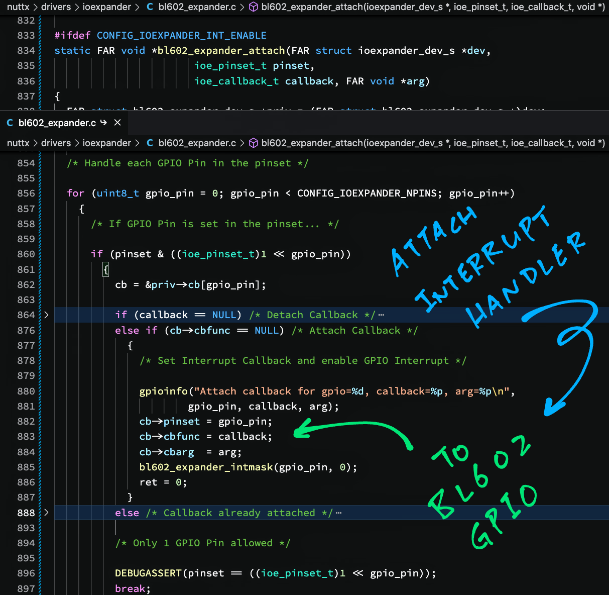
Here’s how our GPIO Expander attaches an Interrupt Callback: bl602_expander.c
//  Attach a Callback Function to a GPIO Interrupt
static FAR void *bl602_expander_attach(
  FAR struct ioexpander_dev_s *dev,  //  GPIO Expander
  ioe_pinset_t pinset,      //  Bit N is 1 to indicate Pin N
  ioe_callback_t callback,  //  Callback Function
  FAR void *arg)            //  Callback Argument
{
  FAR struct bl602_expander_dev_s *priv = (FAR struct bl602_expander_dev_s *)dev;
  FAR struct bl602_expander_callback_s *cb = NULL;
  DEBUGASSERT(priv != NULL);

  /* Get exclusive access to the I/O Expander */
  int ret = bl602_expander_lock(priv);
  if (ret < 0) { return NULL; }
We begin by locking the GPIO Expander. (Via a Semaphore)
The function accepts a “Special Pinset”, in which Bit N is 1 to specify GPIO Pin N.
(Not to be confused with BL602 Pinset, which numbers pins sequentially)
We iterate through the bits of the Special Pinset to find the GPIO Pin Number that’s marked…
  /* Handle each GPIO Pin in the pinset. CONFIG_IOEXPANDER_NPINS is 23 */
  for (uint8_t gpio_pin = 0; gpio_pin < CONFIG_IOEXPANDER_NPINS; gpio_pin++)
    {
      /* If GPIO Pin is set in the pinset... */
      if (pinset & ((ioe_pinset_t)1 << gpio_pin))
        {
          cb = &priv->cb[gpio_pin];
If the provided callback is null, we disable the Specific GPIO Interrupt and detach the Interrupt Callback for the GPIO…
          if (callback == NULL) /* Detach Callback */
            {
              /* Disable GPIO Interrupt and clear Interrupt Callback */
              bl602_expander_intmask(gpio_pin, 1);
              cb->pinset = 0;
              cb->cbfunc = NULL;
              cb->cbarg  = NULL;
              ret = 0;
}(bl602_expander_intmask is defined here)
If the provided callback is non-null and there’s no Interrupt Callback for the GPIO…
We attach the Interrupt Callback for the GPIO and enable the Specific GPIO Interrupt…
          else if (cb->cbfunc == NULL) /* Attach Callback */
            {
              /* Set Interrupt Callback and enable GPIO Interrupt */
              cb->pinset = gpio_pin;
              cb->cbfunc = callback;
              cb->cbarg  = arg;
              bl602_expander_intmask(gpio_pin, 0);
              ret = 0;
            }
If there’s an existing Interrupt Callback for the GPIO, we quit because we don’t support multiple Interrupt Callbacks for the same GPIO…
          else /* Callback already attached */
            {
              gpioerr("ERROR: GPIO %d already attached\n", gpio_pin);
              ret = -EBUSY;
            }
This function only supports one GPIO (so technically we don’t support Pinsets)…
          /* Only 1 GPIO Pin allowed */
          DEBUGASSERT(pinset == ((ioe_pinset_t)1 << gpio_pin));
          break;
        }
    }
Finally we unlock the GPIO Expander…
  /* Unlock the I/O Expander and return the handle */
  bl602_expander_unlock(priv);
  return (ret == 0) ? cb : NULL;
}
And return the Callback Handle, which will be passed later to detach the Interrupt Callback.
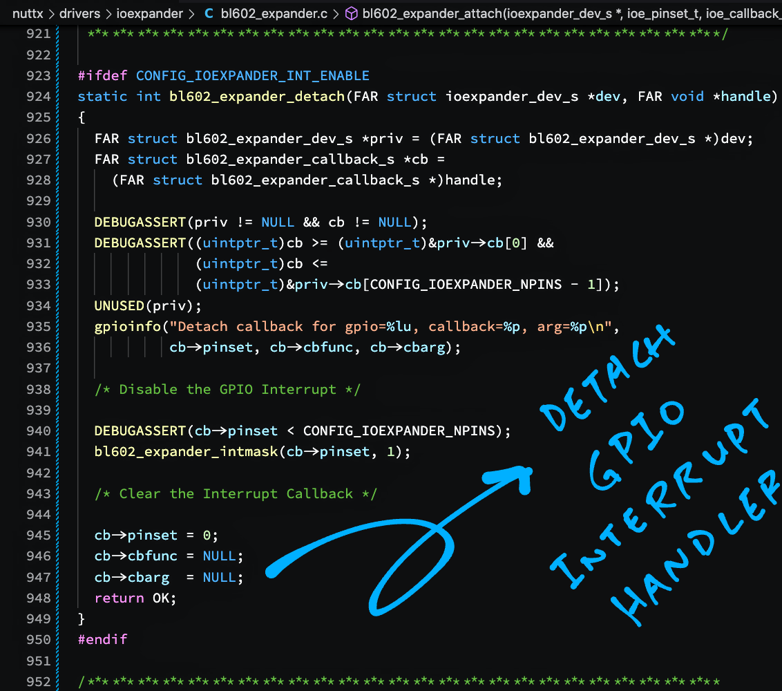
To detach an Interrupt Callback, our GPIO Expander does this: bl602_expander.c
//  Detach and disable a GPIO Interrupt
static int bl602_expander_detach(
  FAR struct ioexpander_dev_s *dev,  //  GPIO Expander
  FAR void *handle)  //  Callback Handle to detach
{
  FAR struct bl602_expander_dev_s *priv = (FAR struct bl602_expander_dev_s *)dev;
  FAR struct bl602_expander_callback_s *cb =
    (FAR struct bl602_expander_callback_s *)handle;
  DEBUGASSERT(priv != NULL && cb != NULL);
  DEBUGASSERT((uintptr_t)cb >= (uintptr_t)&priv->cb[0] &&
              (uintptr_t)cb <=
              (uintptr_t)&priv->cb[CONFIG_IOEXPANDER_NPINS - 1]);
The function accepts a Callback Handle that’s returned when we attach an Interrupt Callback. (See this)
We disable the Specific GPIO Interrupt for the GPIO…
  /* Disable the GPIO Interrupt */
  DEBUGASSERT(cb->pinset < CONFIG_IOEXPANDER_NPINS);
  bl602_expander_intmask(cb->pinset, 1);
And we clear the Interrupt Callback for the GPIO…
  /* Clear the Interrupt Callback */
  cb->pinset = 0;
  cb->cbfunc = NULL;
  cb->cbarg  = NULL;
  return OK;
}(bl602_expander_intmask is defined here)
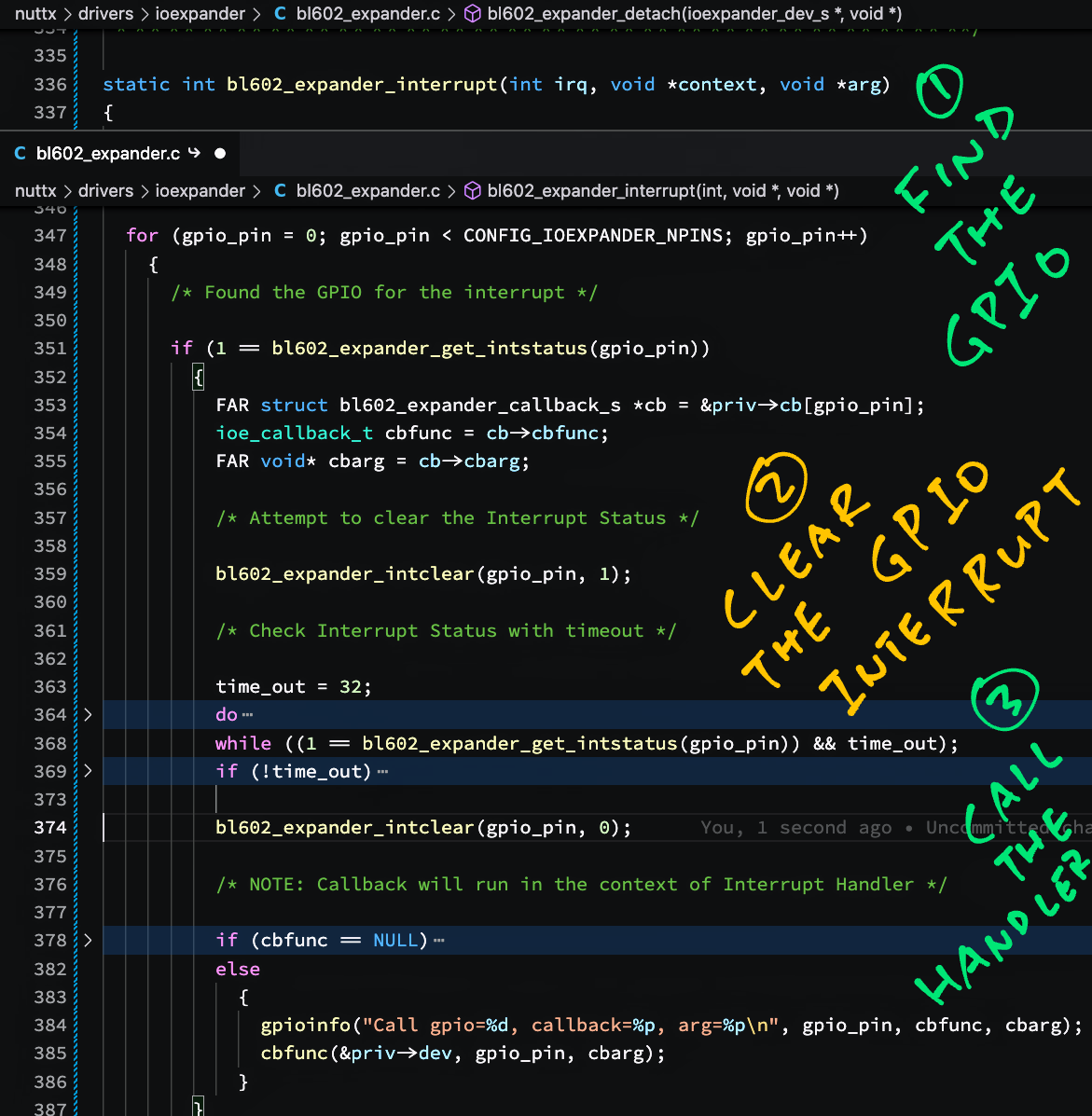
Below is the GPIO Expander Interrupt Handler that handles the GPIO IRQ Interrupt.
The interrupt-handling logic was copied from the BL602 EVB GPIO Driver, so some details are a little fuzzy.
(Like clearing the Interrupt Status)
Remember that all GPIO Interrupts are multiplexed to a single GPIO IRQ.
When the GPIO IRQ is triggered, we check the Interrupt Status of each GPIO and handle accordingly: bl602_expander.c
//  Handle GPIO Interrupt. Based on
//  https://github.com/apache/nuttx/blob/master/boards/risc-v/bl602/bl602evb/src/bl602_gpio.c#L256-L304
static int bl602_expander_interrupt(
  int irq,        //  IRQ Number
  void *context,  //  Interrupt Context
  void *arg)      //  Interrupt Argument
{
  FAR struct bl602_expander_dev_s *priv = (FAR struct bl602_expander_dev_s *)arg;
  uint32_t time_out = 0;
  uint8_t gpio_pin;
  DEBUGASSERT(priv != NULL);

  /* TODO: Check only the GPIO Pins that have registered for interrupts. CONFIG_IOEXPANDER_NPINS is 23 */
  for (gpio_pin = 0; gpio_pin < CONFIG_IOEXPANDER_NPINS; gpio_pin++)
    {
      /* Found the GPIO for the interrupt */
      if (1 == bl602_expander_get_intstatus(gpio_pin))
        {
          FAR struct bl602_expander_callback_s *cb = &priv->cb[gpio_pin];
          ioe_callback_t cbfunc = cb->cbfunc;
FAR void* cbarg = cb->cbarg;(bl602_expander_get_intstatus is defined here)
When we find the GPIO that triggered the interrupt, we attempt to clear the Interrupt Status for the Specific GPIO…
          /* Attempt to clear the Interrupt Status */
bl602_expander_intclear(gpio_pin, 1);(bl602_expander_intclear is defined here)
Then we wait for the Interrupt Status to be cleared…
          /* Check Interrupt Status with timeout */
          time_out = 32;
          do { time_out--; }
          while ((1 == bl602_expander_get_intstatus(gpio_pin)) && time_out);

          /* Timeout for clearing the Interrupt Status */
          if (!time_out) { gpiowarn("WARNING: Clear GPIO interrupt status fail.\n"); }
We clear the Interrupt Status again, this time setting to 0 instead of 1…
          /* If time_out==0, Interrupt Status not cleared */
          bl602_expander_intclear(gpio_pin, 0);
(Why?)
Finally we call the Callback Function that was attached to the GPIO…
          /* NOTE: Callback will run in the context of Interrupt Handler */
          if (cbfunc == NULL)
            {
              gpioinfo("Missing callback for GPIO %d\n", gpio_pin);
            }
          else
            {
              gpioinfo("Call gpio=%d, callback=%p, arg=%p\n", gpio_pin, cbfunc, cbarg);
              cbfunc(&priv->dev, gpio_pin, cbarg);
            }
        }
    }
  return OK;
}
And we’re done handling the GPIO IRQ Interrupt!