📝 7 Feb 2021
PineCone and Pinenut BL602 work great with I2C Sensors. (See this)
But what if we’re connecting BL602 to High Bandwidth peripherals… Like the ST7789 Display Controller and the SX1262 LoRa Transceiver?
We’ll need SPI on BL602!
Today we shall connect the BL602 RISC-V SoC to a simple SPI Sensor: BME280
We’ll learn about the SPI quirks on BL602 and how we fixed them…
Serial Data In and Serial Data Out seem to be flipped
SPI Phase 1 behaves like Phase 0
Why we shouldn’t use Pin 0 for SPI
Why we should control SPI Chip Select ourselves
Also we’ll learn to troubleshoot BL602 SPI with a Logic Analyser.
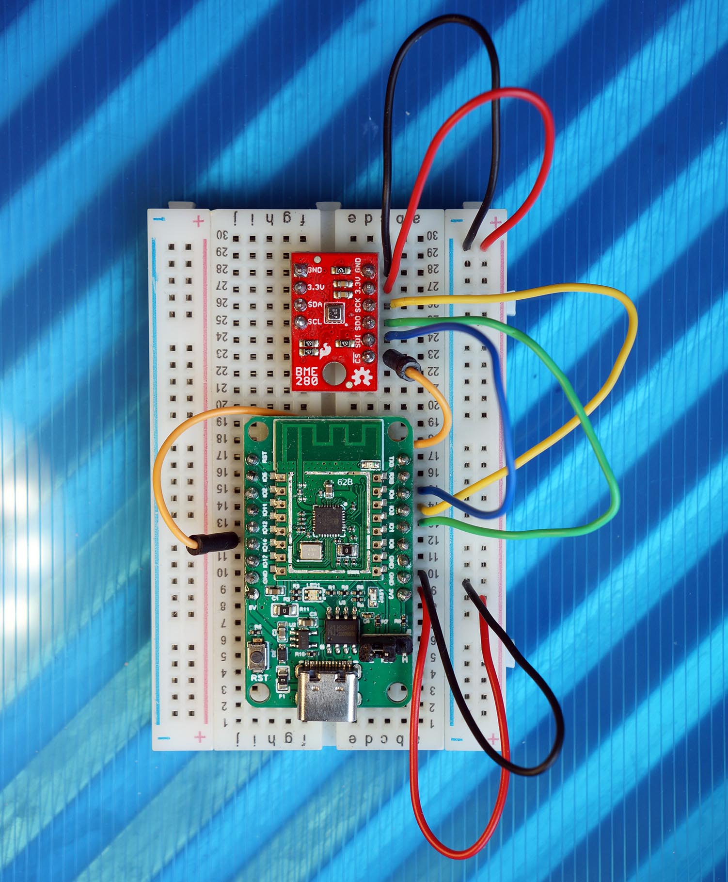
PineCone BL602 RISC-V Board connected to BME280 SPI Sensor
Humans evolve… So do the terms that we use!
This article will become obsolete quickly unless we adopt the new names for SPI Pins…
We’ll say “Serial Data In (SDI)” (instead of “MISO”)
And we’ll say “Serial Data Out (SDO)” (instead of “MOSI”)
We’ll refer to BL602 as the “SPI Controller”
And BME280 as the “SPI Peripheral”
Note that Serial Data In and Serial Data Out are flipped across the SPI Controller and the SPI Peripheral…
Serial Data In on BL602 connects to Serial Data Out on BME280
And Serial Data Out on BL602 connects to Serial Data In on BME280
(Yep it works like the Transmit / Receive pins for a UART port)
The BL602 IoT SDK contains an SPI Hardware Abstraction Layer (HAL) that we may call in our C programs to transfer data over SPI…
However there are a couple of concerns over the BL602 SPI HAL…
BL602 SPI HAL doesn’t support all BL602 SPI features.
It supports SPI Transfers via Direct Memory Access (DMA). Which is good for blasting pixels to Display Controllers (like ST7789).
But it doesn’t support byte-by-byte SPI Transfer, like the Arduino SPI HAL for BL602.
BL602 SPI HAL was designed to work with AliOS Things operating system and its Virtual File System.
It uses the AliOS Device Tree for configuring the SPI Port. Which might be overkill for some embedded programs.
I have added an SPI HAL function spi_init that lets us call the SPI HAL without AliOS Things and its Device Tree.
BL602 SPI HAL works only with FreeRTOS.
Unlike the BL602 HALs for GPIO, PWM and I2C, there’s no Low Level HAL that works on all operating systems.
But we may port the SPI HAL to other operating systems by emulating a few FreeRTOS functions for Event Groups. (More about this later)
Hence we can still write SPI programs for BL602 without AliOS. And I’ll highlight the SPI features that have special limitations.
We shall test BL602 SPI with this BL602 Command-Line Firmware that I have created: sdk_app_spi_demo
The firmware will work on all BL602 boards, including PineCone and Pinenut.
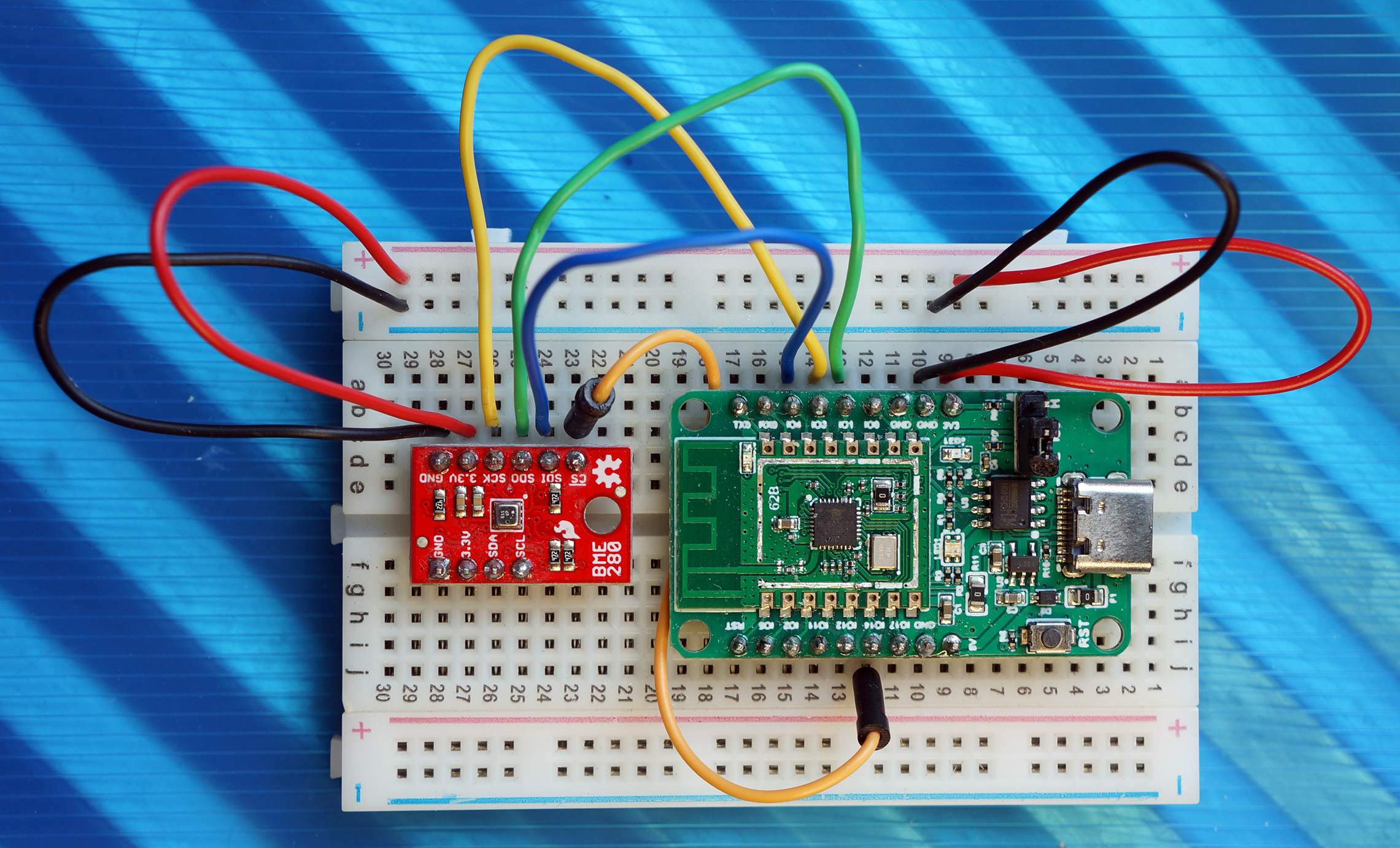
PineCone BL602 connected to SparkFun BME280 Sensor over SPI
Let’s connect BL602 to the Bosch BME280 Sensor for Temperature, Humidity and Air Pressure
(The steps in this article will work for BMP280 too)
BME280 supports two interfaces: SPI (6 pins) and I2C (4 pins). We shall connect to the SPI side of BME280.
Don’t use any pins on the I2C side! (Because the 3V3 pin selects SPI or I2C)
Connect BL602 to BME280 (the SPI side with 6 pins) according to the pic above…
| BL602 Pin | BME280 SPI | Wire Colour |
|---|---|---|
GPIO 1 | SDO (MISO) | Green |
GPIO 2 | Do Not Connect | Do Not Connect |
GPIO 3 | SCK | Yellow |
GPIO 4 | SDI (MOSI) | Blue |
GPIO 14 | CS | Orange |
3V3 | 3.3V | Red |
GND | GND | Black |
We’ll talk about GPIO 2 in a while.
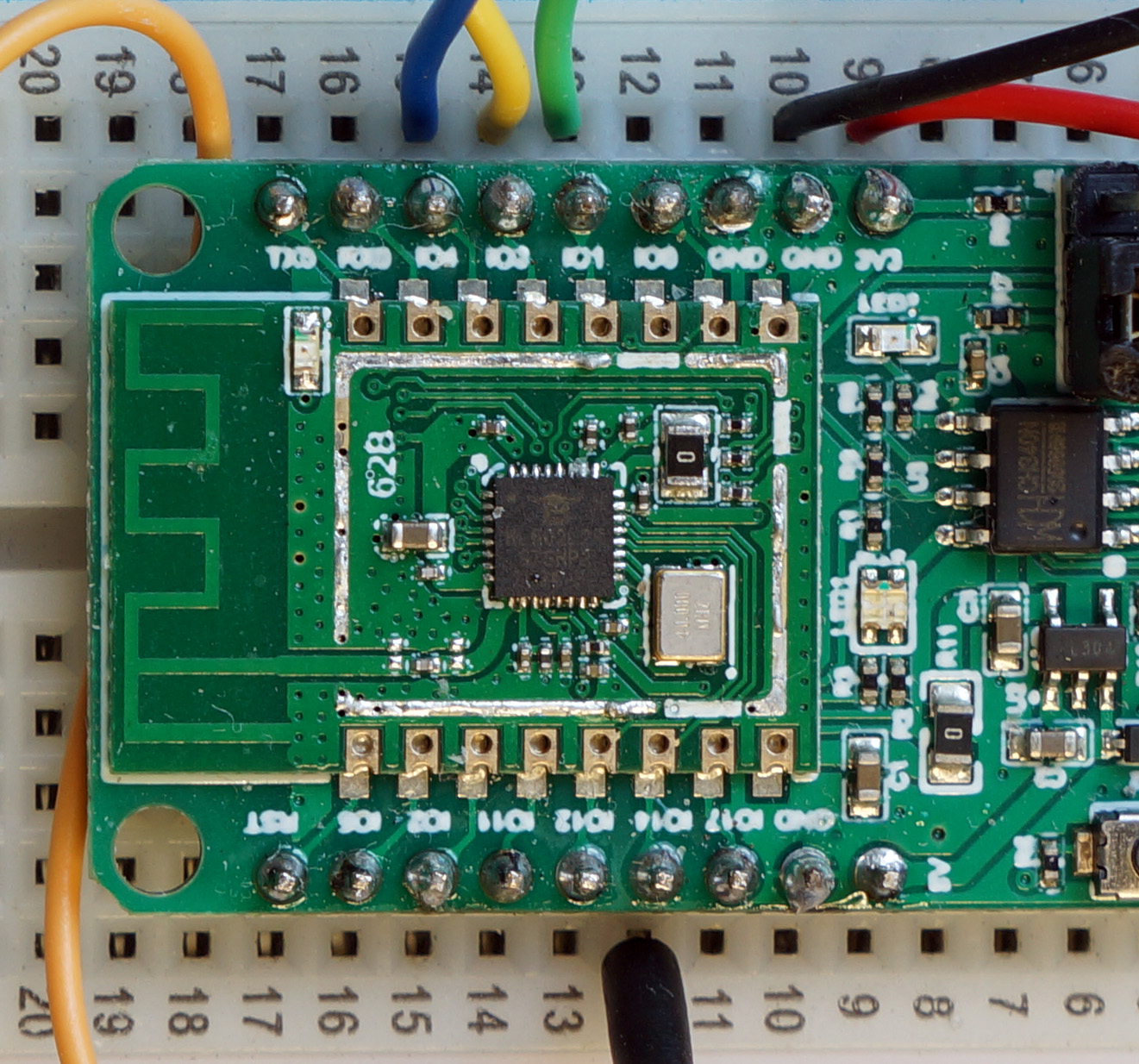
BL602 SPI Pins 1 (SDI), 3 (Clock), 4 (SDO) and 14 (Chip Select)
We’re NOT using the Recommended SPI Pins for PineCone and Pinenut: GPIO 0, 11, 14, 17.
And we’re NOT using the Default SPI Pins for BL602 Device Tree: GPIO 0, 1, 2, 3.
Why did we choose these pins for SPI?
GPIO 0 is connected to the PineCone’s WiFi LED (Is this documented somewhere?)
GPIO 11, 14, 17 are connected to PineCone’s RGB LED
We won’t use these PineCone LED Pins for SPI because…
Somebody else will probably use the LED Pins to control the LEDs. Contention ensues!
Lights switching on for no reason is just plain… Spooky
(Sorry my mistake… I shouldn’t be using Pin 14 for Chip Select. Beware of contention!)
What shall we accomplish with BL602 and BME280?
BME280 has a Chip ID Register, at Register ID 0xD0
Reading the Chip ID Register will give us the Chip ID value 0x60
(0x60 identifies the chip as BME280. For BMP280 the Chip ID is 0x58)
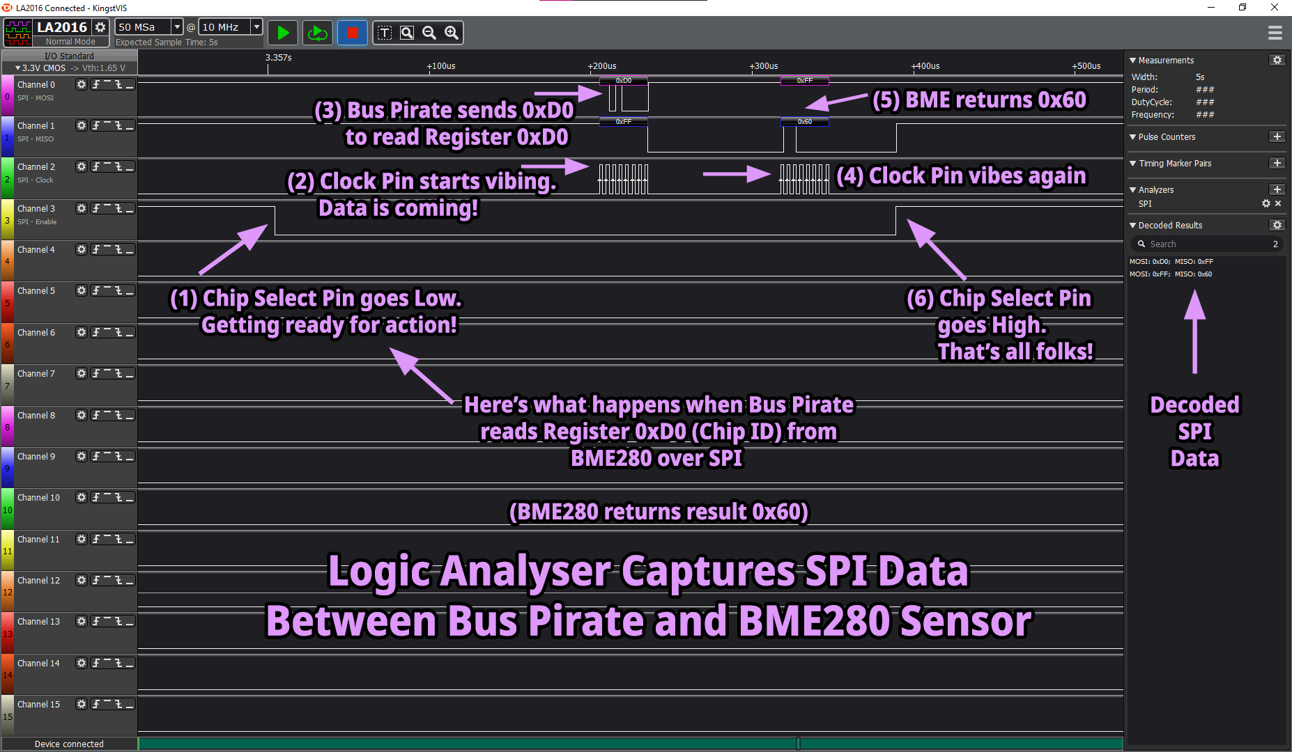
What’s the SPI Data that will be transferred between BL602 and BME280?
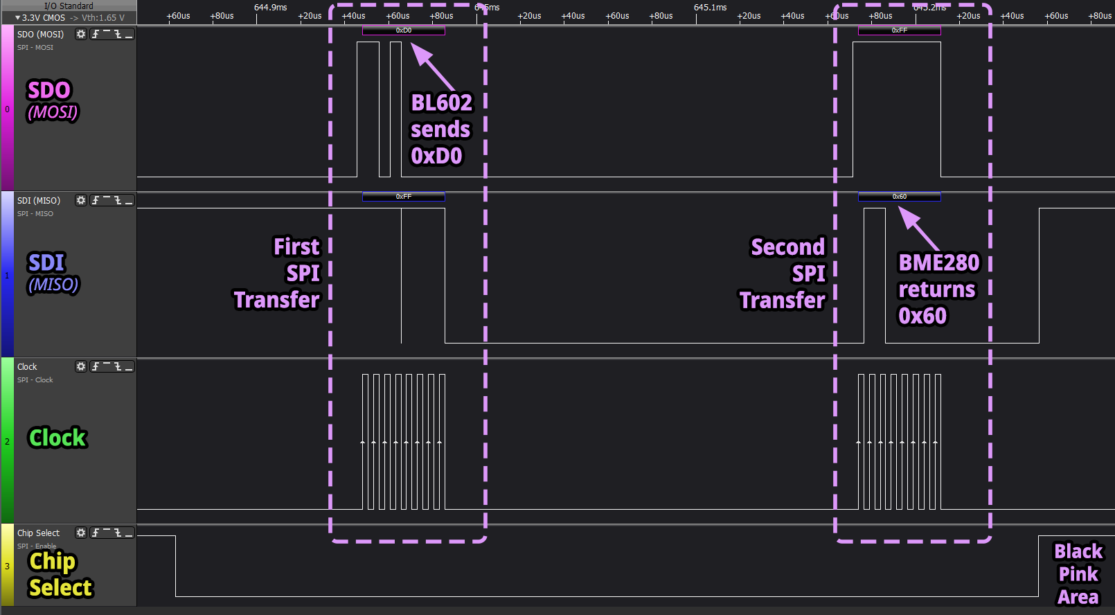
Here’s how BL602 and BME280 will talk over SPI…
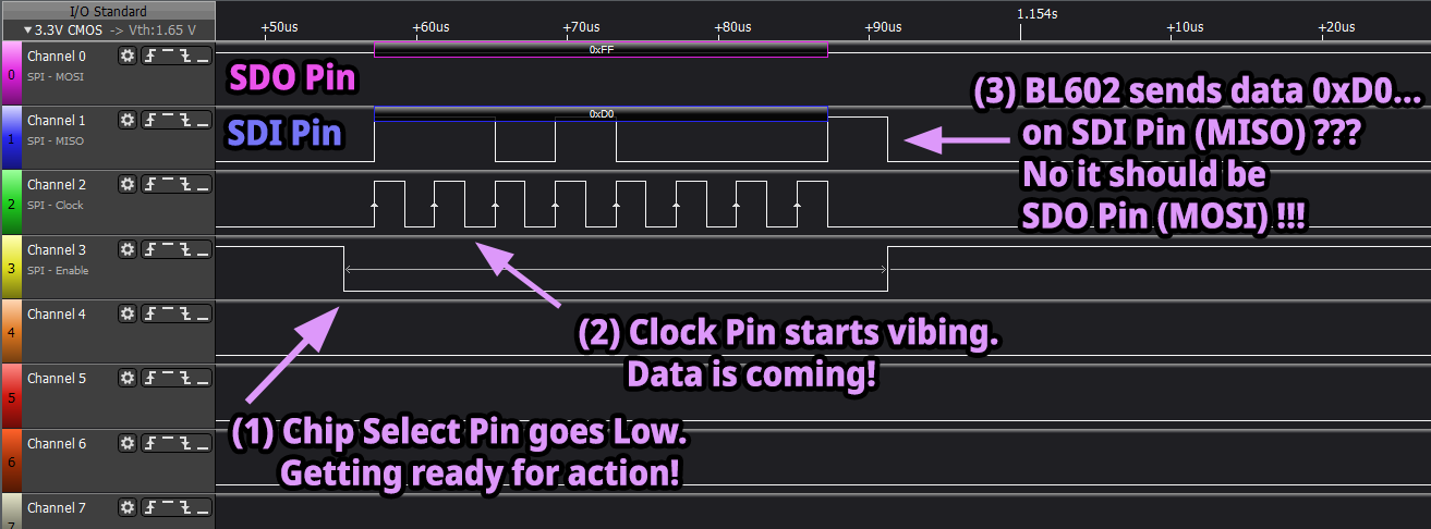
BL602 transmits byte 0xD0 to BME280 on Serial Data Out (formerly MOSI)
BME280 returns byte 0x60 to BL602 on Serial Data In (formerly MISO)
The SPI Chip Select Pin (CS) and SPI Clock Pin (SCK) will frame and synchronise the data transfer…
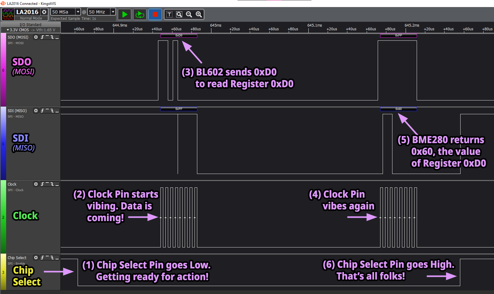
BL602 talks to BME280 over SPI, visualised by a Logic Analyser
Let’s dive into the code for our SPI Demo Firmware!
Before we initialise the SPI Port, we define these constants and variables in sdk_app_spi_demo/demo.c
/// Use SPI Port Number 0
#define SPI_PORT   0

/// Use GPIO 14 as SPI Chip Select Pin
#define SPI_CS_PIN 14

/// SPI Port
static spi_dev_t spi;
SPI_Port is the SPI Port Number. We use the one and only port on BL602: SPI Port 0
SPI_CS_PIN is the Pin Number for the SPI Chip Select Pin. We select Pin 14
spi is the device instance of the SPI Port
Our demo firmware initialises the SPI Port in the function test_spi_init from sdk_app_spi_demo/demo.c
/// Init the SPI Port
static void test_spi_init(char *buf, int len, int argc, char **argv) {
    //  Configure the SPI Port
    int rc = spi_init(
        &spi,        //  SPI Device
        SPI_PORT,    //  SPI Port
        0,           //  SPI Mode: 0 for Controller
        1,           //  SPI Polarity and Phase: 1 for (CPOL=0, CPHA=1)
        200 * 1000,  //  SPI Frequency (200 kHz)
        2,   //  Transmit DMA Channel
        3,   //  Receive DMA Channel
        3,   //  SPI Clock Pin
        2,   //  Unused SPI Chip Select Pin
        1,   //  SPI Serial Data In Pin  (formerly MISO)
        4    //  SPI Serial Data Out Pin (formerly MOSI)
    );
    assert(rc == 0);
This function initialises spi by calling the (custom) BL602 SPI HAL Function spi_init.
(spi_init may only be called once in our firmware, because it maintains a single global instance of SPI device)
Here are the parameters for spi_init…
SPI Device: SPI device instance to be initialised, spi
SPI Port: SPI Port Number 0
SPI Mode: We choose 0 to configure BL602 as SPI Controller. Valid values are…
SPI Polarity and Phase: We choose 1 for Polarity 0 (CPOL), Phase 1 (CPHA). Valid values are…
(There’s a bug with SPI Polarity and Phase, more about this later)
SPI Frequency: We set the SPI Frequency (Hz) to 200,000, which means 200 kHz.
(Slow but reliable, and easier to troubleshoot)
SPI Frequency ranges from 200 kHz to 40 MHz.
Transmit DMA Channel: We select DMA Channel 2 for transmitting SPI Data
Receive DMA Channel: We select DMA Channel 3 for receiving SPI Data
SPI Clock Pin: We select Pin 3
Unused SPI Chip Select Pin: We select Pin 2.
We won’t connect this pin to BME280, but it must NOT be the same as the Actual Chip Select Pin (14)
(More about Chip Select later)
SPI Serial Data In Pin: We select Pin 1 (Formerly MISO)
SPI Serial Data Out Pin: We select Pin 4 (Formerly MOSI)
Next we configure the Actual Chip Select Pin (14) as a GPIO Pin…
    //  Configure Chip Select pin as a GPIO Pin
    GLB_GPIO_Type pins[1];
    pins[0] = SPI_CS_PIN;
    BL_Err_Type rc2 = GLB_GPIO_Func_Init(
        GPIO_FUN_SWGPIO,  //  Configure as GPIO
        pins,             //  Pins to be configured (Pin 14)
        sizeof(pins) / sizeof(pins[0])  //  Number of pins (1)
    );
    assert(rc2 == SUCCESS);
(We’ll find out why later)
Because we’re not ready to talk to BME280 yet, we set the Chip Select Pin to High to deactivate BME280…
    //  Configure Chip Select pin as a GPIO Output Pin (instead of GPIO Input)
    rc = bl_gpio_enable_output(SPI_CS_PIN, 0, 0);
    assert(rc == 0);

    //  Set Chip Select pin to High, to deactivate BME280
    rc = bl_gpio_output_set(SPI_CS_PIN, 1);
    assert(rc == 0);
}
(More about Chip Select in a while)
Our SPI Port is initialised, all set for transferring data!
(BL602 SPI HAL Function spi_init shall be explained in the Appendix)
SPI Controllers (like BL602) and Peripherals (like BME280) can transmit and receive SPI Data simultaneously… Because SPI allows Full Duplex communication.
When the BL602 SPI HAL executes an SPI Transfer request, it’s transmitting and receiving data simultaneously.
Remember how BL602 and BME280 will talk over SPI?
BL602 transmits byte 0xD0 to BME280
BL602 receives byte 0x60 from BME280
BL602 SPI HAL handles this as two SPI Transfer requests of one byte each…
First SPI Transfer: BL602 transmits byte 0xD0
Second SPI Transfer: BL602 receives byte 0x60
(Yep there will be “wasted data”… We don’t need the received byte from the first request… And the transmitted byte from the second request)
Let’s construct the two SPI Transfer requests.
First and Second SPI Transfers
First we define the Transmit and Receive Buffers (one byte each) for the two SPI Transfers: sdk_app_spi_demo/demo.c
/// SPI Transmit and Receive Buffers for First SPI Transfer
static uint8_t tx_buf1[1];  //  We shall transmit Register ID (0xD0)
static uint8_t rx_buf1[1];  //  Unused. We expect to receive the result from BME280 in the second SPI Transfer.

/// SPI Transmit and Receive Buffers for Second SPI Transfer
static uint8_t tx_buf2[1];  //  Unused. For safety, we shall transmit 0xFF which is a read command (not write).
static uint8_t rx_buf2[1]; // We expect to receive Chip ID (0x60) from BME280Let’s look at the function in our demo firmware that creates the two SPI Transfers and executes them: test_spi_transfer from sdk_app_spi_demo/demo.c
/// Start the SPI data transfer
static void test_spi_transfer(char *buf, int len, int argc, char **argv) {
    //  Clear the buffers
    memset(&tx_buf1, 0, sizeof(tx_buf1));
    memset(&rx_buf1, 0, sizeof(rx_buf1));
    memset(&tx_buf2, 0, sizeof(tx_buf2));
    memset(&rx_buf2, 0, sizeof(rx_buf2));

    //  Prepare 2 SPI Transfers
    static spi_ioc_transfer_t transfers[2];
    memset(transfers, 0, sizeof(transfers));
Here we erase the Transmit and Receive Buffers, and prepare two SPI Transfers.
Next we define the First SPI Transfer…
    //  First SPI Transfer: Transmit Register ID (0xD0) to BME280
    tx_buf1[0] = 0xd0;  //  Read BME280 Chip ID Register (0xD0). Read/Write Bit (High Bit) is 1 for Read.
    transfers[0].tx_buf = (uint32_t) tx_buf1;  //  Transmit Buffer (Register ID)
    transfers[0].rx_buf = (uint32_t) rx_buf1;  //  Receive Buffer
    transfers[0].len    = sizeof(tx_buf1);     //  How many bytes
We’ll be transmitting one byte 0xD0 to BME280. This goes into the Transmit Buffer tx_buf1
We set the Transmit and Receive Buffers for the First SPI Transfer in transfers[0]
Also we set the data length of the First SPI Transfer (one byte) in transfers[0]
Then we define the Second SPI Transfer…
    //  Second SPI Transfer: Receive Chip ID (0x60) from BME280
    tx_buf2[0] = 0xff;  //  Unused. Read/Write Bit (High Bit) is 1 for Read.
    transfers[1].tx_buf = (uint32_t) tx_buf2;  //  Transmit Buffer
    transfers[1].rx_buf = (uint32_t) rx_buf2;  //  Receive Buffer (Chip ID)
    transfers[1].len    = sizeof(tx_buf2);     //  How many bytes
BME280 will ignore the byte transmitted by BL602 in the Second SPI Transfer. But let’s send 0xFF for safety. This goes into the Transmit Buffer tx_buf2
We set the Transmit and Receive Buffers for the Second SPI Transfer in transfers[1]
Also we set the data length of the Second SPI Transfer (one byte) in transfers[1]
Now we’re ready to execute the two SPI Transfers!
By SPI Convention, we set the Chip Select Pin to Low to activate BME280 (and get it ready for talking)…
    //  Set Chip Select pin to Low, to activate BME280
    int rc = bl_gpio_output_set(SPI_CS_PIN, 0);
    assert(rc == 0);
Now that we have BME280’s attention, we execute the two SPI Transfers by calling the BL602 SPI HAL Function hal_spi_transfer…
    //  Execute the two SPI Transfers with the DMA Controller
    rc = hal_spi_transfer(
        &spi,       //  SPI Device
        transfers,  //  SPI Transfers
        sizeof(transfers) / sizeof(transfers[0])  //  How many transfers (Number of requests, not bytes)
    );
    assert(rc == 0);

    //  DMA Controller will transmit and receive the SPI data in the background.
    //  hal_spi_transfer will wait for the two SPI Transfers to complete before returning.
hal_spi_transfer will wait for the two SPI Transfers to complete before returning.
When we’re done with the two SPI Transfers, we set the Chip Select Pin to High to deactivate BME280 (and put it to sleep)…
    //  Now that we're done with the two SPI Transfers...
    //  Set Chip Select pin to High, to deactivate BME280
    rc = bl_gpio_output_set(SPI_CS_PIN, 1);
    assert(rc == 0);
}
Mission Accomplished! The Receive Buffer for the Second SPI Transfer rx_buf2 will contain the data received from BME280: 0x60.
We’ll witness this shortly.
(BL602 SPI HAL Function hal_spi_transfer shall be explained in the Appendix)
What’s Direct Memory Access? How does it help SPI?
Direct Memory Access (DMA) is a BL602 hardware feature that will automagically copy data from RAM to the SPI Port (and back)… Without any intervention from our firmware code!
Here’s how SPI works with and without DMA…
SPI Without DMA:
Firmware code transmits and receives 4 bytes of data
(Because BL602 has an SPI buffer size of 4 bytes)
Waits for Transfer Complete Interrupt
Firmware code transmits and receives another 4 bytes of data
Waits for Transfer Complete Interrupt
Repeat until all bytes have been transmitted and received
What if we’re blasting 1,000 bytes to an SPI Display Controller?
Our CPU will be interrupted 250 times to transmit data.
Not so efficient!
SPI With DMA:
Firmware code tells the DMA Controller the addresses of the Transmit and Receive Buffers, and how many bytes to transmit and receive
(BL602 DMA Controller uses a DMA Linked List with two entries: Transmit Buffer and Receive Buffer)
DMA Controller transmits and receives the entire buffer automatically
(Even when the firmware code is running!)
DMA Controller triggers two DMA Complete Interrupts
(One interrupt for Transmit Complete, another interrupt for Receive Complete)
What if we’re blasting 1,000 bytes to an SPI Display Controller?
Our CPU will be interrupted only twice!
That’s super efficient!
All SPI Transfers done with the BL602 SPI HAL will use super-efficient DMA.
To learn more about SPI with DMA…
SPI Demo Firmware for BL602
Let’s run the SPI Demo Firmware for BL602.
Download the Firmware Binary File sdk_app_spi_demo.bin from…
Alternatively, we may build the Firmware Binary File sdk_app_spi_demo.bin from the source code…
## Download the master branch of lupyuen's bl_iot_sdk
git clone --recursive --branch master https://github.com/lupyuen/bl_iot_sdk
cd bl_iot_sdk/customer_app/sdk_app_spi_demo

## TODO: Change this to the full path of bl_iot_sdk
export BL60X_SDK_PATH=$HOME/bl_iot_sdk
export CONFIG_CHIP_NAME=BL602
make

## For WSL: Copy the firmware to /mnt/c/blflash, which refers to c:\blflash in Windows
mkdir /mnt/c/blflash
cp build_out/sdk_app_spi_demo.bin /mnt/c/blflash
More details on building bl_iot_sdk
Follow these steps to install blflash…
We assume that our Firmware Binary File sdk_app_spi_demo.bin has been copied to the blflash folder.
Set BL602 to Flashing Mode and restart the board.
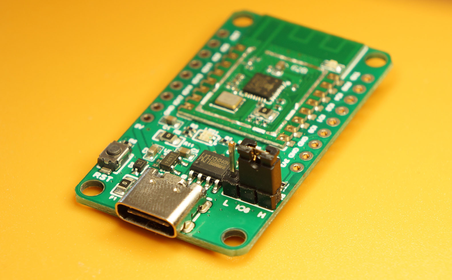
For PineCone:
Set the PineCone Jumper (IO 8) to the H Position (Like this)
Press the Reset Button
For BL10:
Connect BL10 to the USB port
Press and hold the D8 Button (GPIO 8)
Press and release the EN Button (Reset)
Release the D8 Button
For Ai-Thinker Ai-WB2, Pinenut and MagicHome BL602:
Disconnect the board from the USB Port
Connect GPIO 8 to 3.3V
Reconnect the board to the USB port
Enter these commands to flash sdk_app_spi_demo.bin to BL602 over UART…
## For Linux:
blflash flash build_out/sdk_app_spi_demo.bin \
    --port /dev/ttyUSB0

## For macOS:
blflash flash build_out/sdk_app_spi_demo.bin \
    --port /dev/tty.usbserial-1420 \
    --initial-baud-rate 230400 \
    --baud-rate 230400

## For Windows: Change COM5 to the BL602 Serial Port
blflash flash c:\blflash\sdk_app_spi_demo.bin --port COM5
(For WSL: Do this under plain old Windows CMD, not WSL, because blflash needs to access the COM port)
More details on flashing firmware
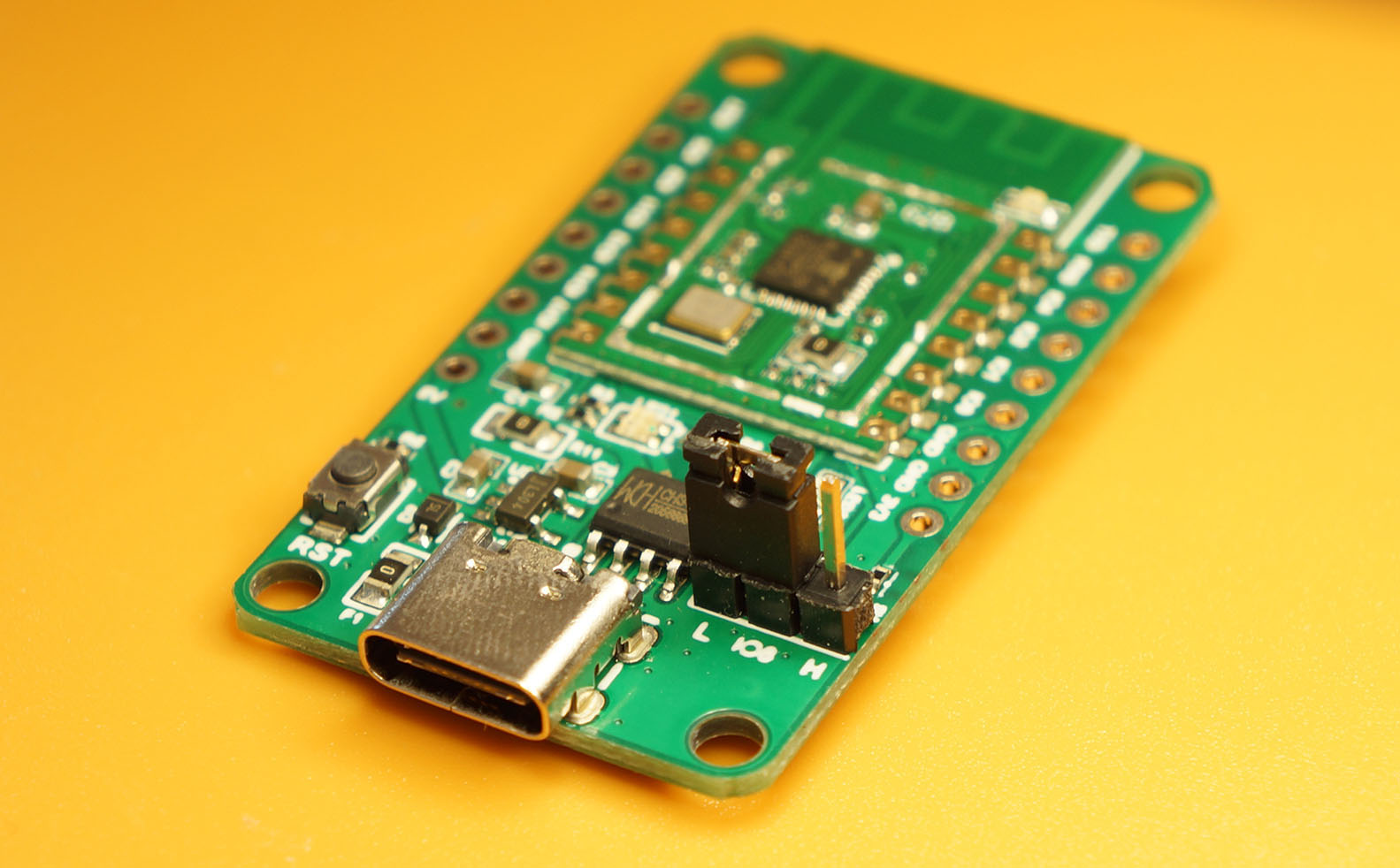
Set BL602 to Normal Mode (Non-Flashing) and restart the board…
For PineCone:
Set the PineCone Jumper (IO 8) to the L Position (Like this)
Press the Reset Button
For BL10:
For Ai-Thinker Ai-WB2, Pinenut and MagicHome BL602:
Disconnect the board from the USB Port
Connect GPIO 8 to GND
Reconnect the board to the USB port
After restarting, connect to BL602’s UART Port at 2 Mbps like so…
For Linux:
screen /dev/ttyUSB0 2000000For macOS: Use CoolTerm (See this)
For Windows: Use putty (See this)
Alternatively: Use the Web Serial Terminal (See this)
More details on connecting to BL602
Let’s enter some SPI commands to read our BME280 Sensor!
Press Enter to reveal the command prompt.
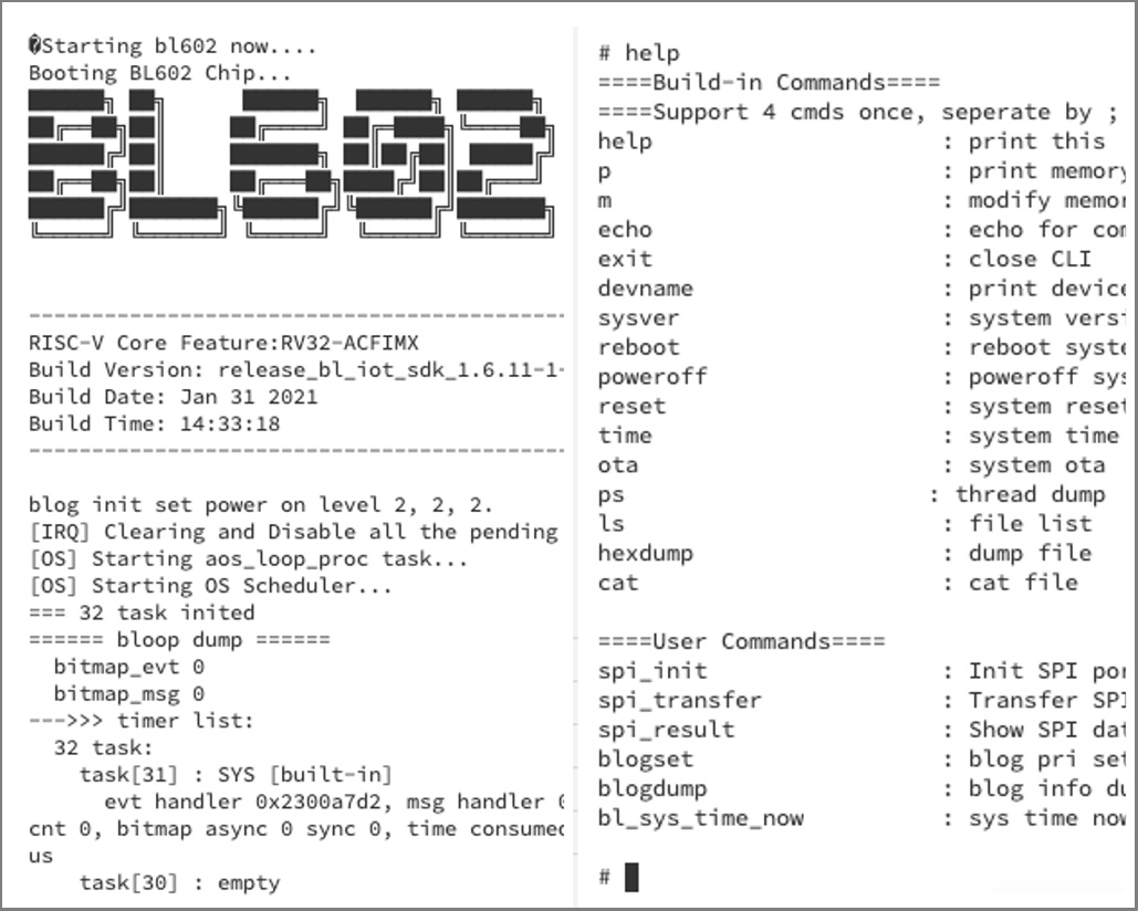
Enter help to see the available commands…
help
====User Commands====
spi_init                 : Init SPI port
spi_transfer             : Transfer SPI data
spi_result               : Show SPI data received
First we initialise our SPI Port.
Enter this command…
spi_initspi_init calls the function test_spi_init, which we have seen earlier.
We should see this…
port0 eventloop init = 42010b48
[HAL] [SPI] Init :
port=0, mode=0, polar_phase = 1, freq=200000, tx_dma_ch=2, rx_dma_ch=3, pin_clk=3, pin_cs=2, pin_mosi=1, pin_miso=4
set rwspeed = 200000
hal_gpio_init: cs:2, clk:3, mosi:1, miso: 4
hal_gpio_init: SPI controller mode
hal_spi_init.
Set CS pin 14 to high
Now we start the two SPI Transfers…
spi_transferspi_transfer calls the function test_spi_transfer, which we have seen earlier.
We should see this…
Set CS pin 14 to low
hal_spi_transfr = 2
transfer xfer[0].len = 1
Tx DMA src=0x4200d1b8, dest=0x4000a288, size=1, si=1, di=0, i=1
Rx DMA src=0x4000a28c, dest=0x4200d1b0, size=1, si=0, di=1, i=1
recv all event group.
transfer xfer[1].len = 1
Tx DMA src=0x4200d1bc, dest=0x4000a288, size=1, si=1, di=0, i=1
Rx DMA src=0x4000a28c, dest=0x4200d1b4, size=1, si=0, di=1, i=1
recv all event group.
Set CS pin 14 to high
Finally we display the SPI Data received from BME280…
spi_result(spi_result is defined here in sdk_app_spi_demo/demo.c)
We should see this…
SPI Transfer #1: Received Data 0x0x4200d1b0:
ff
SPI Transfer #2: Received Data 0x0x4200d1b4:
60
Tx Interrupts: 2
Tx Status:     0x0
Tx Term Count: 0x0
Tx Error:      0x0
Rx Interrupts: 2
Rx Status:     0x0
Rx Term Count: 0x0
Rx Error:      0x0
This shows that we have encountered two Transmit Interrupts and two Receive Interrupts, no errors. Which is expected for two SPI Transfers.
Remember that we’re reading the Chip ID from BME280. We should see this Chip ID under SPI Transfer #2…
60(For BMP280 the Chip ID is 0x58)
Congratulations! We have successfully read the BME280 Sensor from BL602 over SPI!
Earlier we said that we’re not using Pin 2, the designated Chip Select Pin from the BL602 SPI Port…
//  Configure the SPI Port
int rc = spi_init(
    ...
    2,   //  Unused SPI Chip Select Pin
But instead, we’re using Pin 14 as our own Chip Select Pin…
/// Use GPIO 14 as SPI Chip Select Pin
#define SPI_CS_PIN 14
Why are we controlling the Chip Select Pin ourselves?
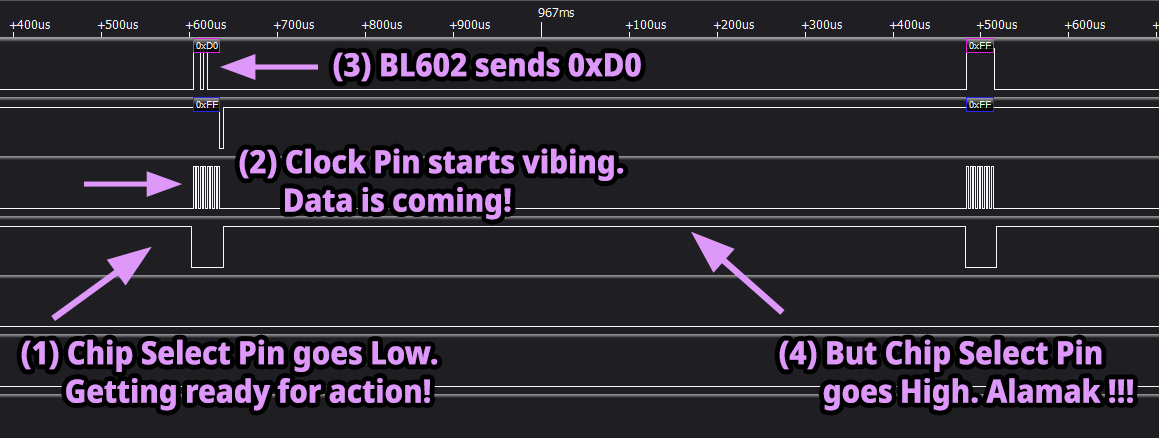
We get to shape the Chip Select Signal ourselves
When we use the Chip Select Pin from the SPI Port, the Chip Select Pin goes High between the two SPI Transfers. (See pic above)
This is not good… We expect the Chip Select Pin to stay Low between the two SPI Transfers! (See this)
We’ll control the Chip Select Pin ourselves to produce the desired signal shape.
(It’s like shaping our own eyebrows… We have complete control!)
(How do we know that the Chip Select Pin should stay Low? From the Bus Pirate data captured by the Logic Analyser. See this)
We want to control multiple SPI Peripherals with BL602
We may connect multiple SPI Peripherals to BL602 at the same time: BME280 Sensor, ST7789 Display Controller, SX1262 LoRa Transceiver, …
BL602’s Serial Data In, Serial Data Out and Clock Pins may be shared by the SPI Peripherals… But each SPI Periperhal needs its own Chip Select Pin.
Hence we’ll control the Chip Select Pin ourselves to support multiple SPI Peripherals.
Read on to learn how we use BL602 GPIO to control our Chip Select Pin.
(Remember: Don’t use Pin 2 for any other purpose… Because the SPI Port is still controlling it!)
BL602 is extremely versatile for Pin Functions… We may assign any BL602 Pin as GPIO, SPI, I2C, UART, PWM or JTAG!
(See Table 3.1 “Pin Description”, Page 27 in the BL602 Reference Manual)
We configure Pin 14 for GPIO like so: sdk_app_spi_demo/demo.c
/// Use GPIO 14 as SPI Chip Select Pin
#define SPI_CS_PIN 14

//  Configure Chip Select pin as a GPIO Pin
GLB_GPIO_Type pins[1];
pins[0] = SPI_CS_PIN;
BL_Err_Type rc2 = GLB_GPIO_Func_Init(
    GPIO_FUN_SWGPIO,  //  Configure as GPIO
    pins,             //  Pins to be configured (Pin 14)
    sizeof(pins) / sizeof(pins[0])  //  Number of pins (1)
);
assert(rc2 == SUCCESS);
We call GLB_GPIO_Func_Init to configure Pin 14 as a plain GPIO Pin: GPIO_FUN_SWGPIO.
(GLB_GPIO_Func_Init comes from the BL602 Standard Driver: bl602_glb.c)
Now that Pin 14 is configured as a GPIO Pin, let’s configure it for GPIO Output (instead of GPIO Input)…
//  Configure Chip Select pin as a GPIO Output Pin (instead of GPIO Input)
rc = bl_gpio_enable_output(SPI_CS_PIN, 0, 0);
assert(rc == 0);
We’re ready to toggle Pin 14 as a GPIO Output Pin!
(bl_gpio_enable_output comes from the BL602 GPIO Low Level HAL. See this)
To set our Chip Select Pin to Low (which activates BME280), we do this: sdk_app_spi_demo/demo.c
//  Set Chip Select pin to Low, to activate BME280
int rc = bl_gpio_output_set(SPI_CS_PIN, 0);
assert(rc == 0);
We set Chip Select to Low just before executing the two SPI Transfers.
(bl_gpio_output_set comes from the BL602 GPIO Low Level HAL. See this)
To set our Chip Select Pin to High (which deactivates BME280), we do this…
//  Set Chip Select pin to High, to deactivate BME280
rc = bl_gpio_output_set(SPI_CS_PIN, 1);
assert(rc == 0);
We set Chip Select to High in two places…
When we initialise the SPI Port
After completing the two SPI Transfers
Here’s a strange problem about the BL602 SPI Data Pins that still spooks me today…
Recall that we’re using Pins 1 and 4 as the SPI Data Pins.
Yep BL602 will let us assign Pins 1 and 4 to the SPI Port… But within that SPI Port, each pin serves a fixed SPI Function (like Serial Data In and Serial Data Out).
Here’s what the BL602 Reference Manual says (Table 3.1 “Pin Description”, Page 27)…
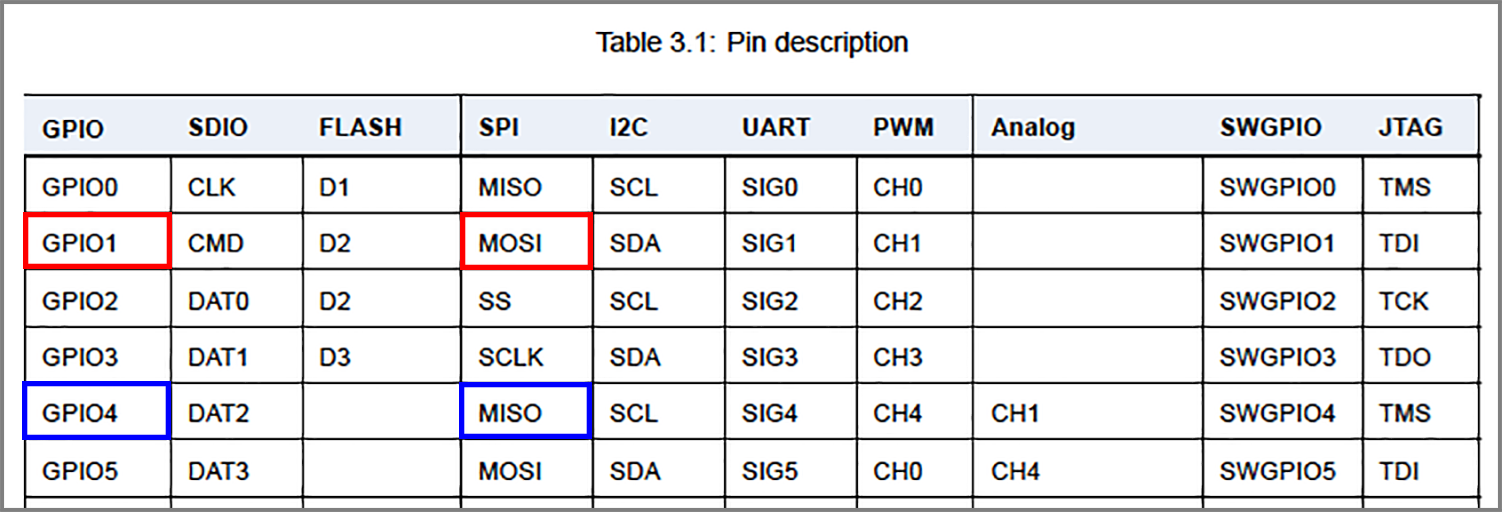
GPIO 1 should be BL602 Serial Data Out (formerly MOSI)
Which connects to BME280 Serial Data In
GPIO 4 should be BL602 Serial Data In (formerly MISO)
Which connects to BME280 Serial Data Out
(Remember that Data In/Out are flipped across BL602 and BME280)
Yet when we connect BL602 to BME280 in the above manner, we’ll see this…
The two BL602 SPI Data Pins are flipped! (According to the Logic Analyser)
This seems to be a bug in the BL602 hardware or documentation. We fix this by flipping the two data pins…
| BL602 Pin | BME280 SPI | Wire Colour |
|---|---|---|
GPIO 1 | SDO | Green |
GPIO 4 | SDI | Blue |
This works perfectly fine, though it contradicts the BL602 Reference Manual.
Because of this bug, we shall refer to Pin 1 as Serial Data In (formerly MISO), and Pin 4 as Serial Data Out (formerly MOSI): sdk_app_spi_demo/demo.c
//  Configure the SPI Port
int rc = spi_init(
    ...
    1,   //  SPI Serial Data In Pin  (formerly MISO)
    4    //  SPI Serial Data Out Pin (formerly MOSI)
(Could we have mistakenly configured BL602 as SPI Peripheral… Instead of SPI Controller? 🤔)
UPDATE: We may call GLB_Swap_SPI_0_MOSI_With_MISO to swap the two SPI Data Pins. (See this)
Here’s another spooky problem: BL602 SPI Phase seems incorrect.
Earlier we have configured BL602 for SPI Polarity 0 (CPOL), Phase 1 (CPHA): sdk_app_spi_demo/demo.c
//  Configure the SPI Port
int rc = spi_init(
    ...
    1,           //  SPI Polarity and Phase: 1 for (CPOL=0, CPHA=1)
Here’s how it looks with a Logic Analyser…
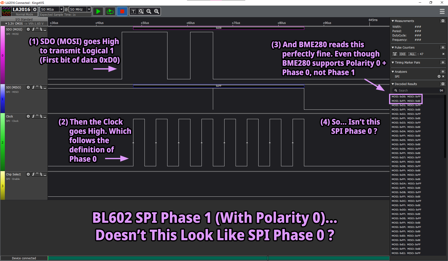
Note that the Serial Data Out Pin (formerly MOSI) goes High… before the Clock Pin goes High.
Now compare this with the SPI Polarity and Phase diagrams here…
Doesn’t this look like SPI Polarity 0 Phase 0, not Phase 1?
Here’s another odd thing: This BL602 SPI Configuration (SPI Polarity 0, Phase 1) works perfectly splendid with BME280…
Yet BME280 doesn’t support SPI Polarity 0, Phase 1!
BME280 only supports…
SPI Polarity 0, Phase 0
SPI Polarity 1, Phase 1
Again this seems to be a bug in the BL602 hardware or documentation.
Be careful when configuring the BL602 SPI Phase… It doesn’t quite work the way we expect!
(Yep I painstakingly verified… Setting BL602 to SPI Polarity 0, Phase 0 doesn’t work with BME280)
To summarise the spooky mysteries we have observed on BL602 SPI…
SPI Pins for Serial Data In and Serial Data Out seem to be flipped, when observed with a Logic Analyser.
This contradicts the BL602 Reference Manual.
To fix this, we flip the Serial Data In and Serial Data Out Pins.
To talk to BME280, we must configure BL602 for SPI Polarity 0 Phase 1.
Though the Logic Analyser shows that BL602 behaves as SPI Polarity 0 Phase 0 (not Phase 1).
Be careful when configuring BL602’s SPI Phase.
Using Pin 0 for SPI will switch on the WiFi LED on PineCone.
(This is undocumented behaviour… What else does Pin 0 do?)
We’ll switch to Pin 4 for SPI Serial Data Out.
(This is neither spooky nor mysterious… But we fixed it anyway)
BL602’s SPI Chip Select Pin doesn’t work with BME280’s SPI protocol.
And it doesn’t support multiple SPI Peripherals.
We’ll control the SPI Chip Select Pin ourselves with GPIO.
We have implemented workarounds for these issues.
BL602 SPI is Good To Go!
BL602 SPI HAL runs on FreeRTOS today. Will the SPI HAL run on other Embedded Operating Systems? Like Mynewt, RIOT, Zephyr, …
We may port the BL602 SPI HAL to other operating systems by emulating these FreeRTOS functions for Event Groups…
xEventGroupCreate: Create an Event Group
(Used by the DMA Interrupt Handlers to notify the Foreground Task)
xEventGroupClearBits: Clear the Event Group
(Called by the Foreground Task)
xEventGroupWaitBits: Wait for Event Group
(Called by the Foreground Task)
xEventGroupSetBitsFromISR: Notify the Event Group
(Called by the DMA Interrupt Handlers)
portYIELD_FROM_ISR: Wakes up the Foreground Task that’s waiting for the Event Group.
(Called by the DMA Interrupt Handlers)
We also need to emulate these FreeRTOS heap memory functions, which are similar to malloc and free…
pvPortMalloc: Allocate heap memory
(For creating the DMA Linked List)
vPortFree: Free the allocated heap memory
(The usage of these functions is explained in the Appendix)
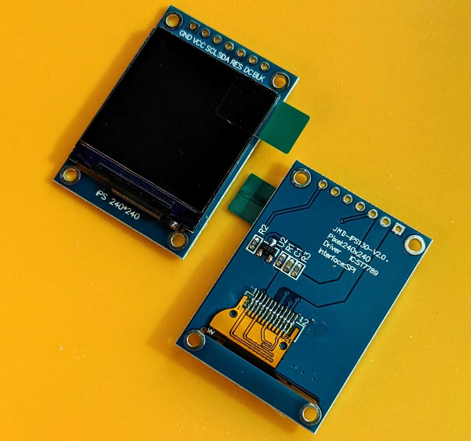
ST7789 Display Controller with SPI Interface
Now that we have SPI working on BL602, let’s test it with the ST7789 Display Controller… And maybe with the LVGL Graphics Library too!
Here’s the article…
BL602 SPI HAL is also used by the Semtech SX1276 / Hope RF96 LoRa Transceiver. Here’s how…
Eventually I’ll be porting BL602 SPI HAL to Apache Mynewt operating system… So that we can build BL602 SPI applications in Rust!
There’s plenty more code in the BL602 IoT SDK to be deciphered and documented: ADC, DAC, WiFi, Bluetooth LE, …
Come Join Us… Make BL602 Better!
🙏 👍 😀
Got a question, comment or suggestion? Create an Issue or submit a Pull Request here…
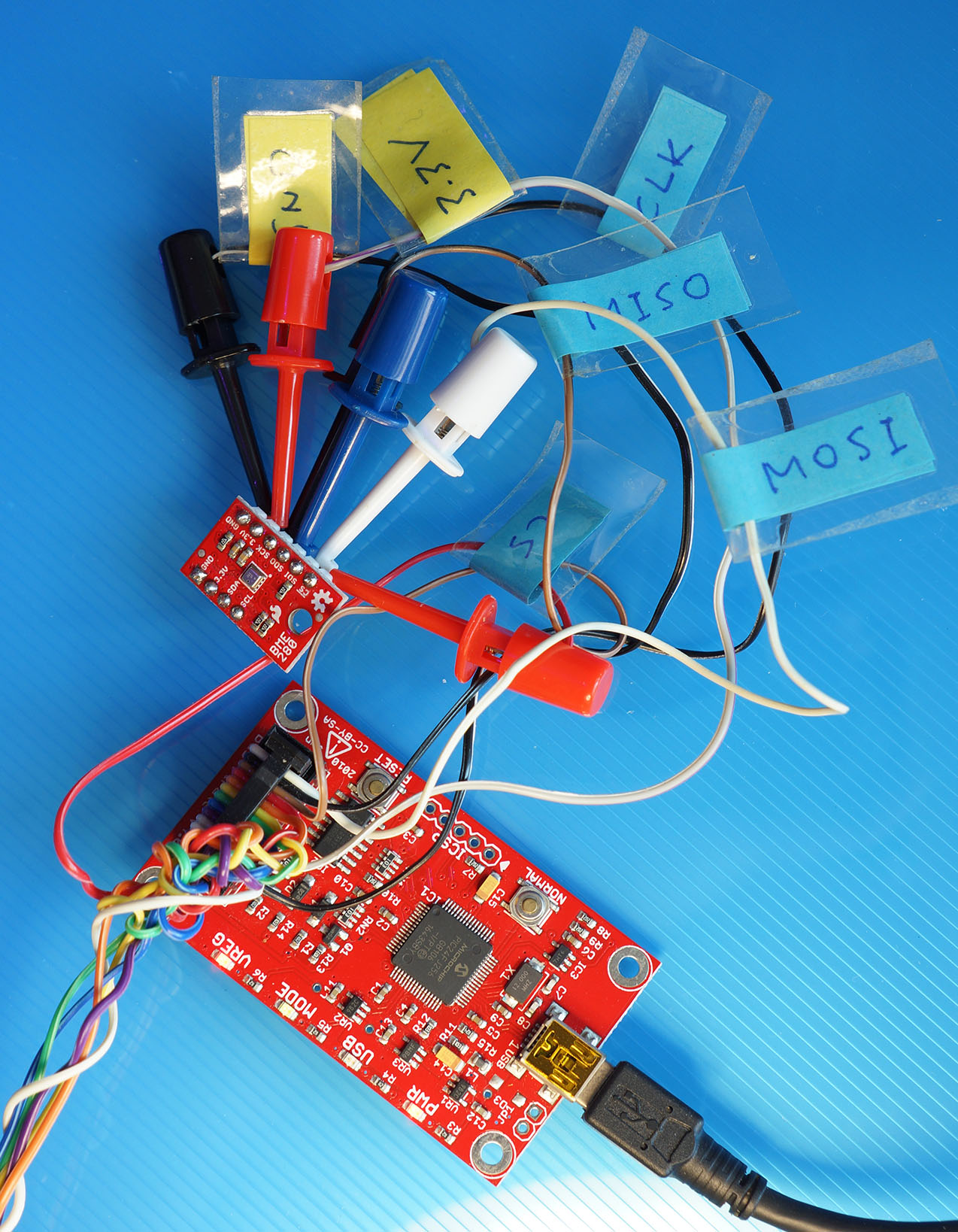
Bus Pirate connected to BME280 Sensor over SPI
Bus Pirate is a useful gadget for verifying whether our BME280 Sensor works OK. And for checking the SPI signals that should be sent down the wire to BME280.
Here’s how we test BME280 (or BMP280) with Bus Pirate…
Connect Bus Pirate to BME280 (or BMP280) according to the pic above…
| Bus Pirate Pin | BME280 SPI Pin |
|---|---|
MOSI | SDI |
MISO | SDO |
CLK | SCK |
CS | CS |
3.3V | 3.3V |
GND | GND |
Connect to the SPI side of BME280 (with 6 pins).
Don’t use any pins on the I2C side (with 4 pins).
Connect Bus Pirate to our computer’s USB port.
Open a Serial Terminal for Bus Pirate.
Enter m to show the menu
Select SPI
HiZ> m
1. HiZ
2. 1-WIRE
3. UART
4. I2C
5. SPI
6. 2WIRE
7. 3WIRE
8. KEYB
9. LCD
10. PIC
11. DIO
x. exit(without change)

(1)> 5
Select 250 kHz
Set speed:
1. 30KHz
2. 125KHz
3. 250KHz
4. 1MHz

(1)> 3
Select Idle Low
Clock polarity:
1. Idle low *default
2. Idle high

(1)>
Select Active To Idle
Output clock edge:
1. Idle to active
2. Active to idle *default

(2)>
Select Middle
Input sample phase:
1. Middle *default
2. End

(1)>
Select /CS
CS:
1. CS
2. /CS *default

(2)>
Select Open Drain
Select output type:
1. Open drain (H=Hi-Z, L=GND)
2. Normal (H=3.3V, L=GND)

(1)>
Clutch disengaged!!!
To finish setup, start up the power supplies with command 'W'
Ready
Enter W to power on BME280
SPI> W
POWER SUPPLIES ON
Clutch engaged!!!
Enter this command…
[ 0xD0 r ](We’ll learn why in a while)
We should see…
SPI> [ 0xD0 r ]
/CS ENABLED
WRITE: 0xD0
READ: 0x60
/CS DISABLED
This means that the result is 0x60, which is the Chip ID for BME280.
(For BMP280 the Chip ID is 0x58)
This Bus Pirate SPI command…
[ 0xD0 r ]Will do this…
Set Chip Select Pin to Low (to activate BME280)
Transmit byte 0xD0 to BME280
Receive one byte from BME280
Set Chip Select Pin to High (to deactivate BME280)
This will read BME280’s Chip ID Register 0xD0.
We expect the byte received to be 0x60, which is the Chip ID for BME280.
(For BMP280 the Chip ID is 0x58)
Check out the SPI Guide for Bus Pirate
Bus Pirate talks to BME280 over SPI, visualised by LA2016 Logic Analyser
To see the actual SPI Signals on each Bus Pirate Pin (shown above), we will use a Logic Analyser.
This is useful for comparing and checking whether BL602 is sending the right SPI Signals to BME280.
The next section explains how.
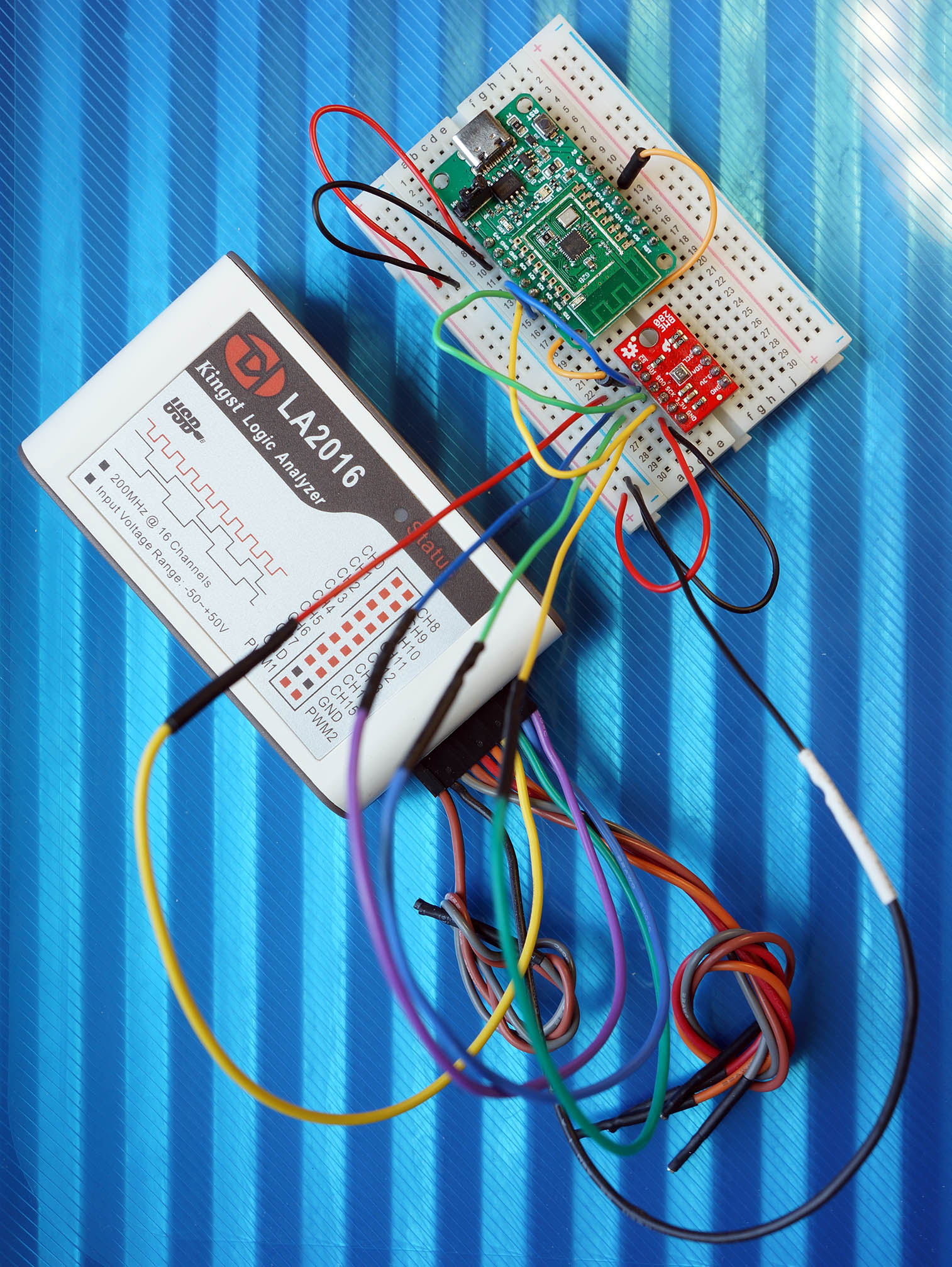
PineCone BL602 RISC-V Board connected to LA2016 Logic Analyser and BME280 SPI Sensor
We shall use the LA2016 Logic Analyser to capture and decode the SPI Signals between BL602 and BME280. (Also between Bus Pirate and BME280)
(LA2016 User Guide is in the link above, under “Learn and Documents”)
Connect the Logic Analyser to BL602 according to the pic above…
| Logic Analyser | BL602 Pin |
|---|---|
CH0 | GPIO 4 (SDO / MOSI) |
CH1 | GPIO 1 (SDI / MISO) |
CH2 | GPIO 3 (SCK) |
CH3 | GPIO 14 (CS) |
GND | GND |
But be very careful!
Rule of Single Power Source: Be sure that BL602 and Logic Analyser are powered by the same source… Both must be connected to the same computer!
Also the LA2016 User Guide says that the measured voltage is highly sensitive to grounding. We shall connect BL602 to the Logic Analyser in this sequence…
Disconnect BL602 and Logic Analyser from our computer’s USB ports
Connect GND from BL602 to Logic Analyser
Connect BL602 and Logic Analyser to our computer’s USB ports
Connect the remaining pins from BL602 to Logic Analyser
Then do this…
Launch the Logic Analyser Software on our computer
Start capturing the SPI Signals with the Logic Analyser Software
Open a Serial Terminal to BL602.
Enter the SPI commands to read BME280’s Chip ID Register.
Switch back to the Logic Analyser Software.
Select the SPI Analyser to decode the SPI Signals.
We should see the decoded SPI Signals between BL602 and BME280 on all four SPI pins…
BL602 talks to BME280 over SPI, visualised by LA2016 Logic Analyser
This should look similar to the decoded SPI Signals between Bus Pirate and BME280. (See this)
Let’s walk through the BL602 SPI HAL code and understand how it performs SPI Transfers with DMA.
We haven’t modified any logic in the SPI HAL. (Though we have added some debug code to understand how the HAL works)
We added the function spi_init to initialise the SPI Port without using the AliOS Device Tree.
HAL_SPI_DEBUG is presently set to 1 to enable debug messages.
For production we should change this to 0.
From bl602_hal/hal_spi.c
//  TODO: Change to 0 for production to disable logging
#define HAL_SPI_DEBUG       (1)
HAL_SPI_HARDCS is supposed to control the Chip Select Pin via GPIO… But it doesn’t work according to our testing.
//  TODO: When set to 0, this is supposed to control
//  Chip Select Pin as GPIO (instead of SPI).
//  But this doesn't work, because the pin has been
//  configured for SPI Port, which overrides GPIO.
#define HAL_SPI_HARDCS (1)We added the function spi_init to initialise the SPI Port without using the AliOS Device Tree. This function is called by our demo firmware.
spi_init was derived from these SPI HAL Functions (which use the AliOS Device Tree)…
Note that there is only a single global instance of SPI Data.
spi_init shall only be called once by our firmware.
From bl602_hal/hal_spi.c
//  Global single instance of SPI Data.
//  We support only one instance of SPI Device.
static spi_priv_data_t g_spi_data;

//  Init the SPI Device for DMA without calling AOS and
//  Device Tree. Return non-zero in case of error.
//  Supports only one instance of SPI Device.
//  Based on spi_arg_set_fdt2 and vfs_spi_init_fullname.
int spi_init(spi_dev_t *spi, uint8_t port,
    uint8_t mode, uint8_t polar_phase, uint32_t freq, uint8_t tx_dma_ch, uint8_t rx_dma_ch,
    uint8_t pin_clk, uint8_t pin_cs, uint8_t pin_mosi, uint8_t pin_miso)
{
    assert(spi != NULL);

    //  Use the global single instance of SPI Data
    g_hal_buf = &g_spi_data;
    memset(g_hal_buf, 0, sizeof(spi_priv_data_t));
(The parameters for spi_init are listed here)
We call xEventGroupCreate to create a FreeRTOS Event Group.
This Event Group will be signalled by the DMA Interrupt Handlers to notify the Foreground Task that the DMA Transmit and Receive Requests have been completed.
    //  Create the Event Group for DMA Interrupt Handler to notify Foreground Task
    g_hal_buf->hwspi[port].spi_dma_event_group = xEventGroupCreate();
    blog_info("port%d eventloop init = %08lx\r\n", port,
        (uint32_t)g_hal_buf->hwspi[port].spi_dma_event_group);
    if (NULL == g_hal_buf->hwspi[port].spi_dma_event_group) {
        return -ENOMEM;
    }
We set the internal fields of the SPI device…
    //  Init the SPI Device
    memset(spi, 0, sizeof(spi_dev_t));
    spi->port = port;
    spi->config.mode = mode;
    spi->config.freq  = 0;  //  Will validate and set frequency in hal_spi_set_rwspeed
    g_hal_buf->hwspi[port].ssp_id      = port;
    g_hal_buf->hwspi[port].mode        = mode;
    g_hal_buf->hwspi[port].polar_phase = polar_phase;
    g_hal_buf->hwspi[port].freq        = 0;  //  Will validate and set frequency in hal_spi_set_rwspeed
    g_hal_buf->hwspi[port].tx_dma_ch   = tx_dma_ch;
    g_hal_buf->hwspi[port].rx_dma_ch   = rx_dma_ch;
    g_hal_buf->hwspi[port].pin_clk     = pin_clk;
    g_hal_buf->hwspi[port].pin_cs      = pin_cs;
    g_hal_buf->hwspi[port].pin_mosi    = pin_mosi;
    g_hal_buf->hwspi[port].pin_miso    = pin_miso;

    //  SPI Device points to global single instance of SPI Data
    spi->priv = g_hal_buf;
    blog_info("[HAL] [SPI] Init :\r\nport=%d, mode=%d, polar_phase = %d, freq=%ld, tx_dma_ch=%d, rx_dma_ch=%d, pin_clk=%d, pin_cs=%d, pin_mosi=%d, pin_miso=%d\r\n",
        port, mode, polar_phase, freq, tx_dma_ch, rx_dma_ch, pin_clk, pin_cs, pin_mosi, pin_miso);
(This code is derived from vfs_spi_init_fullname)
Note that we don’t assign the SPI Frequency yet. We’ll assign later in hal_spi_set_rwspeed because the function validates the SPI Frequency.
Finally we call hal_spi_set_rwspeed to set the SPI Frequency, assign the SPI Pins and initialise the DMA Controller…
    //  Init the SPI speed, pins and DMA
    int rc = hal_spi_set_rwspeed(spi, freq);
    assert(rc == 0);
    return rc;
}hal_spi_set_rwspeed is called by spi_init to set the SPI Frequency, assign the SPI Pins and initialise the DMA Controller.
From bl602_hal/hal_spi.c
int hal_spi_set_rwspeed(spi_dev_t *spi_dev, uint32_t speed)
{
    spi_priv_data_t *data;
    int i;
    uint8_t real_flag = 0;
    uint32_t real_speed = 0;

#if (HAL_SPI_DEBUG)
    blog_info("set rwspeed = %ld\r\n", speed);
#endif
    if (spi_dev->config.freq == speed) {
        blog_info("speed not change.\r\n");
        return 0;
    }
Parameter speed is the SPI Frequency (in Hz) from 200,000 (200 kHz) to 40,000,000 (40 MHz).
The Actual SPI Frequency needs to be divisible by 40,000,000.
Here we compute the divisor for the SPI Frequency and derive the Actual SPI Frequency real_speed…
    for (i = 0; i < 256; i++) {
        if (speed == (40000000/(i+1))) {
            real_speed = speed;
            real_flag = 1;
        } else if (speed < (40000000/(i+1))) {
            continue;
        } else {
            break;
        }
    }
We validate that the Actual SPI Frequency is in the range 200 kHz to 40 MHz…
    if (real_flag != 1) {
        if (i == 0) {
            blog_error("The max speed is 40000000 Hz, please set it smaller.");
            return -1;
        } else if (i == 256) {
            blog_error("The min speed is 156250 Hz, please set it bigger.");
            return -1;
        } else {
            if ( ((40000000/(i+1)) - speed) > (speed - (40000000/i)) ) {
                real_speed = (40000000/(i+1));
                blog_info("not support speed: %ld, change real_speed = %ld\r\n", speed, real_speed);
            } else {
                real_speed = (40000000/i);
                blog_info("not support speed: %ld, change real_speed = %ld\r\n", speed, real_speed);
            }
        }
    }
We set the Actual SPI Frequency…
    data = (spi_priv_data_t *)spi_dev->priv;
    data->hwspi[spi_dev->port].freq = real_speed;
    spi_dev->config.freq = real_speed;
Finally we call hal_spi_init to assign the SPI Pins and initialise the DMA Controller.
    hal_spi_init(spi_dev);
    return 0;
}hal_spi_init is called by hal_spi_set_rwspeed to assign the SPI Pins and initialise the DMA Controller.
From bl602_hal/hal_spi.c
int32_t hal_spi_init(spi_dev_t *spi)
{
    int i;
    spi_priv_data_t *data;

    if (!spi) {
        blog_error("arg err.\r\n");
    }

    data = (spi_priv_data_t *)spi->priv;
    if (data == NULL) {
        return -1;
    }
For every SPI Port (there’s only one: SPI Port 0)…
We call hal_gpio_init to assign the SPI Pins and configure the SPI Port as SPI Controller or Peripheral
We call hal_spi_dma_init to initialise the DMA Controller
    for (i = 0; i < SPI_NUM_MAX; i++) {
        hal_gpio_init(&data->hwspi[i]);
        hal_spi_dma_init(&data->hwspi[i]);
    }

#if (HAL_SPI_DEBUG)
    blog_info("hal_spi_init.\r\n");
#endif

    return 0;
}hal_gpio_init is called by hal_spi_init to assign the SPI Pins and configure the SPI Port as SPI Controller or Peripheral.
From bl602_hal/hal_spi.c
static void hal_gpio_init(spi_hw_t *arg)
{
    GLB_GPIO_Type gpiopins[4];

    if (!arg) {
        blog_error("arg err.\r\n");
        return;
    }
    blog_info("hal_gpio_init: cs:%d, clk:%d, mosi:%d, miso: %d\r\n", arg->pin_cs, arg->pin_clk, arg->pin_mosi, arg->pin_miso);
We call GLB_GPIO_Func_Init to assign the four SPI Pins to the SPI Port…
    gpiopins[0] = arg->pin_cs;
    gpiopins[1] = arg->pin_clk;
    gpiopins[2] = arg->pin_mosi;
    gpiopins[3] = arg->pin_miso;
    GLB_GPIO_Func_Init(GPIO_FUN_SPI,gpiopins,sizeof(gpiopins)/sizeof(gpiopins[0]));
The sequence of the SPI Pins doesn’t matter, because each pin has a fixed SPI Function (like Serial Data In, Serial Data Out) within the SPI Port.
(GLB_GPIO_Func_Init comes from the BL602 Standard Driver: bl602_glb.c)
Finally we configure the SPI Port as SPI Controller or Peripheral…
    if (arg->mode == 0) {
        blog_info("hal_gpio_init: SPI controller mode\r\n");
        GLB_Set_SPI_0_ACT_MOD_Sel(GLB_SPI_PAD_ACT_AS_MASTER);
    } else {
        blog_info("hal_gpio_init: SPI peripheral mode\r\n");
        GLB_Set_SPI_0_ACT_MOD_Sel(GLB_SPI_PAD_ACT_AS_SLAVE);
    }
    return;
}hal_spi_dma_init is called by hal_spi_init to initialise the DMA Controller.
From bl602_hal/hal_spi.c
static void hal_spi_dma_init(spi_hw_t *arg)
{
    spi_hw_t *hw_arg = arg;
    SPI_CFG_Type spicfg;
    SPI_ClockCfg_Type clockcfg;
    SPI_FifoCfg_Type fifocfg;
    SPI_ID_Type spi_id;
    uint8_t clk_div;
    spi_id = hw_arg->ssp_id;
We configure the Timing Intervals for the SPI Clock (according to the Actual SPI Frequency)…
Length of the Start Condition
Length of the Stop Condition
Length of Phase 0
Length of Phase 1
Interval between each frame of data
    /* clock */
    /*1  --->  40 Mhz
     *2  --->  20 Mhz
     *5  --->  8  Mhz
     *6  --->  6.66 Mhz
     *10 --->  4 Mhz
     * */
    clk_div = (uint8_t)(40000000 / hw_arg->freq);
    GLB_Set_SPI_CLK(ENABLE,0);
    clockcfg.startLen      = clk_div;
    clockcfg.stopLen       = clk_div;
    clockcfg.dataPhase0Len = clk_div;
    clockcfg.dataPhase1Len = clk_div;
    clockcfg.intervalLen   = clk_div;
    SPI_ClockConfig(spi_id, &clockcfg);
(This is currently a Square Wave… But we may shape the SPI Clock if necessary)
We set the SPI Configuration: Deglitching, Continuous Chip Enable, Byte Sequence, Bit Sequence, Frame Size…
    /* spi config */
    spicfg.deglitchEnable = DISABLE;
    spicfg.continuousEnable = ENABLE;
    spicfg.byteSequence = SPI_BYTE_INVERSE_BYTE0_FIRST,
    spicfg.bitSequence = SPI_BIT_INVERSE_MSB_FIRST,
    spicfg.frameSize = SPI_FRAME_SIZE_8;
We set the SPI Polarity and Phase…
    if (hw_arg->polar_phase == 0) {
        spicfg.clkPhaseInv = SPI_CLK_PHASE_INVERSE_0;
        spicfg.clkPolarity = SPI_CLK_POLARITY_LOW;
    } else if (hw_arg->polar_phase == 1) {
        spicfg.clkPhaseInv = SPI_CLK_PHASE_INVERSE_1;
        spicfg.clkPolarity = SPI_CLK_POLARITY_LOW;
    } else if (hw_arg->polar_phase == 2) {
        spicfg.clkPhaseInv = SPI_CLK_PHASE_INVERSE_0;
        spicfg.clkPolarity = SPI_CLK_POLARITY_HIGH;
    } else if (hw_arg->polar_phase == 3) {
        spicfg.clkPhaseInv = SPI_CLK_PHASE_INVERSE_1;
        spicfg.clkPolarity = SPI_CLK_POLARITY_HIGH;
    } else {
        blog_error("node support polar_phase \r\n");
    }
We initialise the SPI Port and disable it. We disable all interrupts.
    //  TODO: In future when there are multiple
    //  SPI ports, this should be
    //  SPI_Init(spi_id, &spicfg)
    SPI_Init(0,&spicfg);
    if (hw_arg->mode == 0)
    {
        SPI_Disable(spi_id, SPI_WORK_MODE_MASTER);
    } else {
        SPI_Disable(spi_id, SPI_WORK_MODE_SLAVE);
    }
    SPI_IntMask(spi_id,SPI_INT_ALL,MASK);
We configure the SPI FIFO (First-In First-Out Queue) Threshold, and use DMA for FIFO…
    /* fifo */
    fifocfg.txFifoThreshold = 1;
    fifocfg.rxFifoThreshold = 1;
    fifocfg.txFifoDmaEnable = ENABLE;
    fifocfg.rxFifoDmaEnable = ENABLE;
    SPI_FifoConfig(spi_id,&fifocfg);
SPI FIFO is the Transmit / Receive Queue for SPI. The SPI FIFO Transmit and Receive Queues can buffer up to 4 bytes each…
SPI Transmit FIFO: spi_fifo_wdata at 0x4000a288
SPI Receive FIFO: spi_fifo_rdata at 0x4000a28c
When we set the SPI FIFO Thresholds to 1 (txFifoThreshold and rxFifoThreshold), the SPI Port will notify the DMA Controller whenever one byte has been transmitted or received, so that the DMA Controller will copy the next transmit / receive byte.
Next we configure the Transmit DMA Interrupts…
    DMA_Disable();
    DMA_IntMask(hw_arg->tx_dma_ch, DMA_INT_ALL, MASK);
    DMA_IntMask(hw_arg->tx_dma_ch, DMA_INT_TCOMPLETED, UNMASK);
    DMA_IntMask(hw_arg->tx_dma_ch, DMA_INT_ERR, UNMASK);
Then we configure the Receive DMA Interrupts and enable the DMA interrupts…
    DMA_IntMask(hw_arg->rx_dma_ch, DMA_INT_ALL, MASK);
    DMA_IntMask(hw_arg->rx_dma_ch, DMA_INT_TCOMPLETED, UNMASK);
    DMA_IntMask(hw_arg->rx_dma_ch, DMA_INT_ERR, UNMASK);
    bl_irq_enable(DMA_ALL_IRQn);
Finally we register the DMA Interrupt Handlers…
Transmit DMA Interrupt Handler: bl_spi0_dma_int_handler_tx
This will be triggered when an SPI DMA Transmit Request completes (successfully or unsuccessfully)
Receive DMA Interrupt Handler: bl_spi0_dma_int_handler_rx
This will be triggered when an SPI DMA Receive Request completes (successfully or unsuccessfully)
    bl_dma_irq_register(hw_arg->tx_dma_ch, bl_spi0_dma_int_handler_tx, NULL, NULL);
    bl_dma_irq_register(hw_arg->rx_dma_ch, bl_spi0_dma_int_handler_rx, NULL, NULL);
    return;
}hal_spi_transfer is called by our demo firmware to execute multiple SPI Transfers with DMA.
hal_spi_transfer is a Blocking Function… It waits for the SPI Transfers to complete before returning.
From bl602_hal/hal_spi.c
int hal_spi_transfer(spi_dev_t *spi_dev, void *xfer, uint8_t size)
{
    uint16_t i;
    spi_ioc_transfer_t * s_xfer;
    spi_priv_data_t *priv_data;

    if ((!spi_dev) || (!xfer)) {
        blog_error("arg err.\r\n");
        return -1;
    }

    priv_data = (spi_priv_data_t *)spi_dev->priv;
    if (priv_data == NULL) {
        blog_error("priv_data NULL.\r\n");
        return -1;
    }

    s_xfer = (spi_ioc_transfer_t *)xfer;

#if (HAL_SPI_DEBUG)
    blog_info("hal_spi_transfer = %d\r\n", size);
#endif
Parameter xfer contains an array of SPI Transfers (spi_ioc_transfer_t).
Parameter size specifies the number of SPI Transfers in xfer.
If HAL_SPI_HARDCS is 0, this code is supposed to set the Chip Select Pin to Low via GPIO (which activates the SPI Peripheral). But it doesn’t work.
#if (0 == HAL_SPI_HARDCS)
    blog_info("Set CS pin %d to low\r\n", priv_data->hwspi[spi_dev->port].pin_cs);
    bl_gpio_output_set(priv_data->hwspi[spi_dev->port].pin_cs, 0);
#endif
For every SPI Transfer: We call hal_spi_dma_trans to execute the SPI Transfer, and wait for the SPI Transfer to complete.
    for (i = 0; i < size; i++) {
#if (HAL_SPI_DEBUG)
        blog_info("transfer xfer[%d].len = %ld\r\n", i, s_xfer[i].len);
#endif
        hal_spi_dma_trans(&priv_data->hwspi[spi_dev->port],
                (uint8_t *)s_xfer[i].tx_buf, (uint8_t *)s_xfer[i].rx_buf, s_xfer[i].len);
    }
If HAL_SPI_HARDCS is 0, this code is supposed to set the Chip Select Pin to High via GPIO (which deactivates the SPI Peripheral). But it doesn’t work.
#if (0 == HAL_SPI_HARDCS)
    bl_gpio_output_set(priv_data->hwspi[spi_dev->port].pin_cs, 1);
    blog_info("Set CS pin %d to high\r\n", priv_data->hwspi[spi_dev->port].pin_cs);
#endif
    return 0;
}BL602’s DMA Controller accepts a DMA Linked List of DMA Requests that will be executed automatically.
In lli_list_init we’ll create two DMA Linked Lists of DMA Requests…
One DMA Linked List for SPI Transmit: Copy data from RAM to SPI Port for transmission
Another DMA Linked List for SPI Receive: Copy received data from SPI Port to RAM
lli_list_init is called by hal_spi_dma_trans.
From bl602_hal/hal_spi.c
static int lli_list_init(DMA_LLI_Ctrl_Type **pptxlli, DMA_LLI_Ctrl_Type **pprxlli, uint8_t *ptx_data, uint8_t *prx_data, uint32_t length)
{
    uint32_t i = 0;
    uint32_t count;
    uint32_t remainder;
    struct DMA_Control_Reg dmactrl;
Each DMA Transfer Request is limited to 2048 bytes (LLI_BUFF_SIZE).
To execute larger requests, we break them into smaller requests of 2048 bytes each, and add them to the DMA Linked List…
    count = length / LLI_BUFF_SIZE;
    remainder = length % LLI_BUFF_SIZE;

    if (remainder != 0) {
        count = count + 1;
    }
We define the parameters for the DMA Request…
    dmactrl.SBSize = DMA_BURST_SIZE_1;
    dmactrl.DBSize = DMA_BURST_SIZE_1;
    dmactrl.SWidth = DMA_TRNS_WIDTH_8BITS;
    dmactrl.DWidth = DMA_TRNS_WIDTH_8BITS;
    dmactrl.Prot = 0;
    dmactrl.SLargerD = 0;
We call pvPortMalloc (from FreeRTOS) to allocate heap memory for storing the DMA Linked List…
    *pptxlli = pvPortMalloc(sizeof(DMA_LLI_Ctrl_Type) * count);
    if (*pptxlli == NULL) {
        blog_error("malloc lli failed. \r\n");
        return -1;
    }
    *pprxlli = pvPortMalloc(sizeof(DMA_LLI_Ctrl_Type) * count);
    if (*pprxlli == NULL) {
        blog_error("malloc lli failed.");
        vPortFree(*pptxlli);
        return -1;
    }
For every chunk of SPI Transfer (max 2048 bytes):
We create the DMA Requests for each chunk of SPI Transmit and SPI Receive (max 2048 bytes)…
for (i = 0; i < count; i++) {We compute the DMA Transmit / Receive Size…
        if (remainder == 0) {
            dmactrl.TransferSize = LLI_BUFF_SIZE;
        } else {
            if (i == count - 1) {
                dmactrl.TransferSize = remainder;
            } else {
                dmactrl.TransferSize = LLI_BUFF_SIZE;
            }
        }
For SPI Transmit: We configure the DMA Automatic Address Accumulation for Source (SI) and Destination (DI)…
        dmactrl.SI = DMA_MINC_ENABLE;
        dmactrl.DI = DMA_MINC_DISABLE;
The BL602 Reference Manual doesn’t explain Automatic Address Accumulation. (See Section 6.3.2 “DMA Channel Configuration”, Page 73)
(In the original Chinese docs, “Automatic Address Accumulation” actually means “Automatic Address Increment”. See this)
Let’s assume that the above configuration will auto-increment the Source RAM Address (SI) when the DMA Controller copies data from RAM to the SPI Port.
We don’t auto-increment the Destination Address (DI) because the SPI Port uses a single address for transmitting data: spi_fifo_wdata at 0x4000a288
(DMA_MINC_ENABLE means “Enable Memory Increment Mode”, DMA_MINC_DISABLE means “Disable Memory Increment Mode”. See this)
We set I to 1 if this is the last entry in the DMA Linked List…
        if (i == count - 1) {
            dmactrl.I = 1;
        } else {
            dmactrl.I = 0;
        }
For SPI Transmit: We create a DMA Request that copies data from RAM to the SPI Port for transmission…
        (*pptxlli)[i].srcDmaAddr = (uint32_t)(ptx_data + i * LLI_BUFF_SIZE);
        (*pptxlli)[i].destDmaAddr = (uint32_t)(SPI_BASE+SPI_FIFO_WDATA_OFFSET);
        (*pptxlli)[i].dmaCtrl = dmactrl;

        blog_info("Tx DMA src=0x%x, dest=0x%x, size=%d, si=%d, di=%d, i=%d\r\n", (unsigned) (*pptxlli)[i].srcDmaAddr, (unsigned) (*pptxlli)[i].destDmaAddr, dmactrl.TransferSize, dmactrl.SI, dmactrl.DI, dmactrl.I);
For SPI Receive: We configure the DMA Automatic Address Accumulation (Increment) for Source (SI) and Destination (DI)…
        dmactrl.SI = DMA_MINC_DISABLE;
        dmactrl.DI = DMA_MINC_ENABLE;
Let’s assume that this will auto-increment the Destination RAM Address (DI) when the DMA Controller copies the received data from the SPI Port to RAM.
We don’t auto-increment the Source Address (SI) because the SPI Port uses a single address for receiving data: spi_fifo_rdata at 0x4000a28c
(DMA_MINC_ENABLE means “Enable Memory Increment Mode”, DMA_MINC_DISABLE means “Disable Memory Increment Mode”. See this)
For SPI Receive: We create a DMA Request that copies the received data from the SPI Port to RAM…
        (*pprxlli)[i].srcDmaAddr = (uint32_t)(SPI_BASE+SPI_FIFO_RDATA_OFFSET);
        (*pprxlli)[i].destDmaAddr = (uint32_t)(prx_data + i * LLI_BUFF_SIZE);
        (*pprxlli)[i].dmaCtrl = dmactrl;

        blog_info("Rx DMA src=0x%x, dest=0x%x, size=%d, si=%d, di=%d, i=%d\r\n", (unsigned) (*pprxlli)[i].srcDmaAddr, (unsigned) (*pprxlli)[i].destDmaAddr, dmactrl.TransferSize, dmactrl.SI, dmactrl.DI, dmactrl.I);
Finally we append both DMA Requests to the DMA Linked Lists (Transmit and Receive)…
        if (i != 0) {
            (*pptxlli)[i-1].nextLLI = (uint32_t)&(*pptxlli)[i];
            (*pprxlli)[i-1].nextLLI = (uint32_t)&(*pprxlli)[i];
        }

        (*pptxlli)[i].nextLLI = 0;
        (*pprxlli)[i].nextLLI = 0;
    }
    return 0;
}
Here’s the debug output from lli_list_init when it creates the DMA Linked Lists (Transmit and Receive) for our two SPI Transfers…
DMA Linked Lists (Transmit and Receive) for First SPI Transfer:
Tx DMA src=0x4200d1b8, dest=0x4000a288, size=1, si=1, di=0, i=1
Rx DMA src=0x4000a28c, dest=0x4200d1b0, size=1, si=0, di=1, i=1
The Transmit DMA Linked List Tx DMA copies the data from our first Transmit Buffer tx_buf1 to the SPI Port…
Tx DMA src is the address of our first Transmit Buffer tx_buf1
Tx DMA dest is the address of the SPI Transmit FIFO: spi_fifo_wdata at 0x4000a288
The Receive DMA Linked List Rx DMA copies the received data from the SPI Port to our first Receive Buffer rx_buf1…
Rx DMA src is the address of the SPI Receive FIFO: spi_fifo_rdata at 0x4000a28c
Rx DMA dest is the address of our first Receive Buffer rx_buf1
DMA Linked Lists (Transmit and Receive) for Second SPI Transfer:
Tx DMA src=0x4200d1bc, dest=0x4000a288, size=1, si=1, di=0, i=1
Rx DMA src=0x4000a28c, dest=0x4200d1b4, size=1, si=0, di=1, i=1
The Transmit DMA Linked List Tx DMA copies the data from our second Transmit Buffer tx_buf2 to the SPI Port…
Tx DMA src is the address of our second Transmit Buffer tx_buf2
Tx DMA dest is the address of the SPI Transmit FIFO: spi_fifo_wdata at 0x4000a288
The Receive DMA Linked List Rx DMA copies the received data from the SPI Port to our second Receive Buffer rx_buf2…
Rx DMA src is the address of the SPI Receive FIFO: spi_fifo_rdata at 0x4000a28c
Rx DMA dest is the address of our second Receive Buffer rx_buf2
hal_spi_dma_trans is called by hal_spi_transfer to execute an SPI Transfer with DMA, and wait for the SPI Transfer to complete.
From bl602_hal/hal_spi.c
static void hal_spi_dma_trans(spi_hw_t *arg, uint8_t *TxData, uint8_t *RxData, uint32_t Len)
{
    EventBits_t uxBits;
    DMA_LLI_Cfg_Type txllicfg;
    DMA_LLI_Cfg_Type rxllicfg;
    DMA_LLI_Ctrl_Type *ptxlli;
    DMA_LLI_Ctrl_Type *prxlli;
    int ret;

    if (!arg) {
        blog_error("arg err.\r\n");
        return;
    }
We define the DMA Request for SPI Transmit…
    txllicfg.dir = DMA_TRNS_M2P;
    txllicfg.srcPeriph = DMA_REQ_NONE;
    txllicfg.dstPeriph = DMA_REQ_SPI_TX;
DMA_TRNS_M2P means Memory to Peripheral Transfer
DMA_REQ_SPI_TX says that the destination is the SPI Transmit Port
We define the DMA Request for SPI Receive…
    rxllicfg.dir = DMA_TRNS_P2M;
    rxllicfg.srcPeriph = DMA_REQ_SPI_RX;
    rxllicfg.dstPeriph = DMA_REQ_NONE;
DMA_TRNS_P2M means Peripheral to Memory Transfer
DMA_REQ_SPI_RX says that the source is the SPI Receive Port
We clear the Event Group (from FreeRTOS) so that we can be signalled by the DMA Interrupt Handlers (when the DMA Requests are done)…
xEventGroupClearBits(arg->spi_dma_event_group, EVT_GROUP_SPI_DMA_TR);We disable the DMA Channels and DMA Interrupts…
    DMA_Channel_Disable(arg->tx_dma_ch);
    DMA_Channel_Disable(arg->rx_dma_ch);
    bl_dma_int_clear(arg->tx_dma_ch);
    bl_dma_int_clear(arg->rx_dma_ch);
We enable the DMA Controller and enable SPI for Controller or Peripheral mode…
    DMA_Enable();
    if (arg->mode == 0) {
        SPI_Enable(arg->ssp_id, SPI_WORK_MODE_MASTER);
    } else {
        SPI_Enable(arg->ssp_id, SPI_WORK_MODE_SLAVE);
    }
We call lli_list_init to create the DMA Linked Lists (Transmit and Receive) that will contain every SPI Transfer…
    ret = lli_list_init(&ptxlli, &prxlli, TxData, RxData, Len);
    if (ret < 0) {
        blog_error("init lli failed. \r\n");
        return;
    }
We assign the DMA Linked Lists (Transmit and Receive) to the DMA Controller…
    DMA_LLI_Init(arg->tx_dma_ch, &txllicfg);
    DMA_LLI_Init(arg->rx_dma_ch, &rxllicfg);
    DMA_LLI_Update(arg->tx_dma_ch, (uint32_t) ptxlli);
    DMA_LLI_Update(arg->rx_dma_ch, (uint32_t) prxlli);
We enable the DMA Channels. The DMA Controller will transfer data according to the DMA Linked Lists…
    DMA_Channel_Enable(arg->tx_dma_ch);
    DMA_Channel_Enable(arg->rx_dma_ch);
We call xEventGroupWaitBits (from FreeRTOS) to wait until the Event Group is signalled by both DMA Interrupt Handlers: Transmit Complete and Receive Complete…
    //  TODO: To troubleshoot SPI Transfers that hang
    //  (like ST7789 above 4 MHz), change...
    //      portMAX_DELAY
    //  To...
    //      100 / portTICK_PERIOD_MS
    //  Which will change the SPI Timeout from
    //  "Wait Forever" to 100 milliseconds.
    //  Then check the Interrupt Counters and Error Codes.
    uxBits = xEventGroupWaitBits(   //  Wait for...
        arg->spi_dma_event_group,   //  Event Group
        EVT_GROUP_SPI_DMA_TR,       //  For BOTH Transmit and Receive to complete
        pdTRUE,                     //  Clear bits on exit
        pdTRUE,                     //  Both Transmit and Receive bits must be set
        portMAX_DELAY               //  Wait forever for both bits to be set
    );

    if ((uxBits & EVT_GROUP_SPI_DMA_TR) == EVT_GROUP_SPI_DMA_TR) {
        blog_info("recv all event group.\r\n");
    }
EVT_GROUP_SPI_DMA_TR is a combination of two Events…
EVT_GROUP_SPI_DMA_TX: The Transmit DMA Interrupt Handler triggers this Event when an SPI DMA Transmit Request completes (successfully or unsuccessfully)
EVT_GROUP_SPI_DMA_RX: The Receive DMA Interrupt Handler triggers this Event when an SPI DMA Receive Request completes (successfully or unsuccessfully)
Thus when we wait for EVT_GROUP_SPI_DMA_TR, we’re waiting for the SPI DMA Transmit AND Receive Requests to complete.
Note that we’re waiting forever until both requests complete. For easier troubleshooting, follow the instructions in the comments above to change the SPI Timeout from portMAX_DELAY to 100 / portTICK_PERIOD_MS
(EVT_GROUP_SPI_DMA_TR is defined here)
Finally we free the heap memory for the DMA Linked Lists (Transmit and Receive)…
    vPortFree(ptxlli);
    vPortFree(prxlli);
}bl_spi0_dma_int_handler_tx is the DMA Interrupt Handler that’s triggered when an SPI DMA Transmit Request completes (successfully or unsuccessfully).
The DMA Interrupt Handler is registered by hal_spi_dma_init.
From bl602_hal/hal_spi.c
void bl_spi0_dma_int_handler_tx(void)
{
    g_tx_counter++;  //  Increment the Transmit Interrupt Counter
    g_tx_status = *(uint32_t *) 0x4000c000;  //  Set the Transmit Status
    g_tx_tc     = *(uint32_t *) 0x4000c004;  //  Set the Transmit Terminal Count
if (g_tx_error == 0) { g_tx_error = *(uint32_t *) 0x4000c00c; } // Set the Transmit Error Code(g_tx_counter, g_tx_status and g_tx_tc are explained here)
We call xEventGroupSetBitsFromISR to notify the Event Group, by triggering the EVT_GROUP_SPI_DMA_TX Event.
Then we call portYIELD_FROM_ISR to wake up the Foreground Task that’s waiting for the SPI DMA Transmit Request to complete (hal_spi_dma_trans).
    BaseType_t xResult = pdFAIL;
    BaseType_t xHigherPriorityTaskWoken = pdFALSE;

    if (NULL != g_hal_buf) {
        bl_dma_int_clear(g_hal_buf->hwspi[0].tx_dma_ch);

        if (g_hal_buf->hwspi[0].spi_dma_event_group != NULL) {
            xResult = xEventGroupSetBitsFromISR(
                g_hal_buf->hwspi[0].spi_dma_event_group,
                EVT_GROUP_SPI_DMA_TX,
                &xHigherPriorityTaskWoken);
        }

        if(xResult != pdFAIL) {
            portYIELD_FROM_ISR(xHigherPriorityTaskWoken);
        }
    } else {
        blog_error("bl_spi0_dma_int_handler_tx no clear isr.\r\n");
    }

    return;
}bl_spi0_dma_int_handler_rx is the DMA Interrupt Handler that’s triggered when an SPI DMA Receive Request completes (successfully or unsuccessfully).
The DMA Interrupt Handler is registered by hal_spi_dma_init.
From bl602_hal/hal_spi.c
void bl_spi0_dma_int_handler_rx(void)
{
    g_rx_counter++;  //  Increment the Receive Interrupt Counter
    g_rx_status = *(uint32_t *) 0x4000c000;  //  Set the Receive Status
    g_rx_tc     = *(uint32_t *) 0x4000c004;  //  Set the Receive Terminal Count
if (g_rx_error == 0) { g_rx_error = *(uint32_t *) 0x4000c00c; } // Set the Receive Error Code(g_rx_counter, g_rx_status and g_rx_tc are explained here)
We call xEventGroupSetBitsFromISR to notify the Event Group, by triggering the EVT_GROUP_SPI_DMA_RX Event.
Then we call portYIELD_FROM_ISR to wake up the Foreground Task that’s waiting for the SPI DMA Receive Request to complete (hal_spi_dma_trans).
    BaseType_t xResult = pdFAIL;
    BaseType_t xHigherPriorityTaskWoken = pdFALSE;

    if (NULL != g_hal_buf) {
        bl_dma_int_clear(g_hal_buf->hwspi[0].rx_dma_ch);

        if (g_hal_buf->hwspi[0].spi_dma_event_group != NULL) {
            xResult = xEventGroupSetBitsFromISR(
                g_hal_buf->hwspi[0].spi_dma_event_group,
                EVT_GROUP_SPI_DMA_RX,
                &xHigherPriorityTaskWoken);
        }

        if(xResult != pdFAIL) {
            portYIELD_FROM_ISR(xHigherPriorityTaskWoken);
        }
    } else {
        blog_error("bl_spi0_dma_int_handler_rx no clear isr.\r\n");
    }
    return;
}To check whether the DMA Interrupts are working correctly, we added Interrupt Counters and captured the Status and Error Codes.
From bl602_hal/hal_spi.c
//  Interrupt Counters for Transmit and Receive
int g_tx_counter;
int g_rx_counter;

//  Status, Terminal Counts and Error Codes for Transmit and Receive
uint32_t g_tx_status;  //  Transmit Status         (from 0x4000c000)
uint32_t g_tx_tc;      //  Transmit Terminal Count (from 0x4000c004)
uint32_t g_tx_error;   //  Transmit Error Code     (from 0x4000c00c)
uint32_t g_rx_status;  //  Receive Status          (from 0x4000c000)
uint32_t g_rx_tc;      //  Receive Terminal Count  (from 0x4000c004)
uint32_t g_rx_error;   //  Receive Error Code      (from 0x4000c00c)
These values are displayed when we enter the SPI Command spi_result.
When we complete two SPI Transfers successfully, we should see these values…
Tx Interrupts: 2
Tx Status:     0x0
Tx Term Count: 0x0
Tx Error:      0x0
Rx Interrupts: 2
Rx Status:     0x0
Rx Term Count: 0x0
Rx Error:      0x0
The Interrupt Counters, Status and Error Codes are set by the DMA Interrupt Handlers…
Transmit DMA Interrupt Handler: bl_spi0_dma_int_handler_tx
This will be triggered when an SPI DMA Transmit Request completes (successfully or unsuccessfully)
Receive DMA Interrupt Handler: bl_spi0_dma_int_handler_rx
This will be triggered when an SPI DMA Receive Request completes (successfully or unsuccessfully)