Tiny tasty treat… PineDio Stack BL604 RISC-V Board
📝 16 Sep 2021
Previously I wrote about testing the prototype PineDio Stack BL604 RISC-V Board…
Today we dive into the most exciting component on PineDio Stack: Semtech SX1262 Transceiver for LoRa and LoRaWAN Networking.
Why LoRa?
LoRa is a Low-Power, Long-Range, Low-Bandwidth wireless network.
LoRa is perfect for IoT Sensor Devices that run on Battery Power. (Or Solar Power)
Since PineDio Stack comes with a Solar Panel, it will work really well for Agriculture Sensors.
(And many other IoT gadgets out there in the sun)
Will LoRa support all kinds of messages?
Not quite. LoRa only supports Short Messages of up to 242 Bytes.
And because LoRa is a Low Power (best effort) network, messages may get dropped.
Which is probably OK for sensor devices that send data periodically.
(But not for texting your friends)
Is LoRa secure?
LoRa messages are delivered securely when we join a LoRaWAN Network.
Though our Security Keys would also need to be stored securely on PineDio Stack.
(We’ll learn how in a while)
Which Pine64 devices will talk LoRa and LoRaWAN?
Once the drivers are implemented, these Pine64 devices will talk LoRa and LoRaWAN to PineDio Stack…

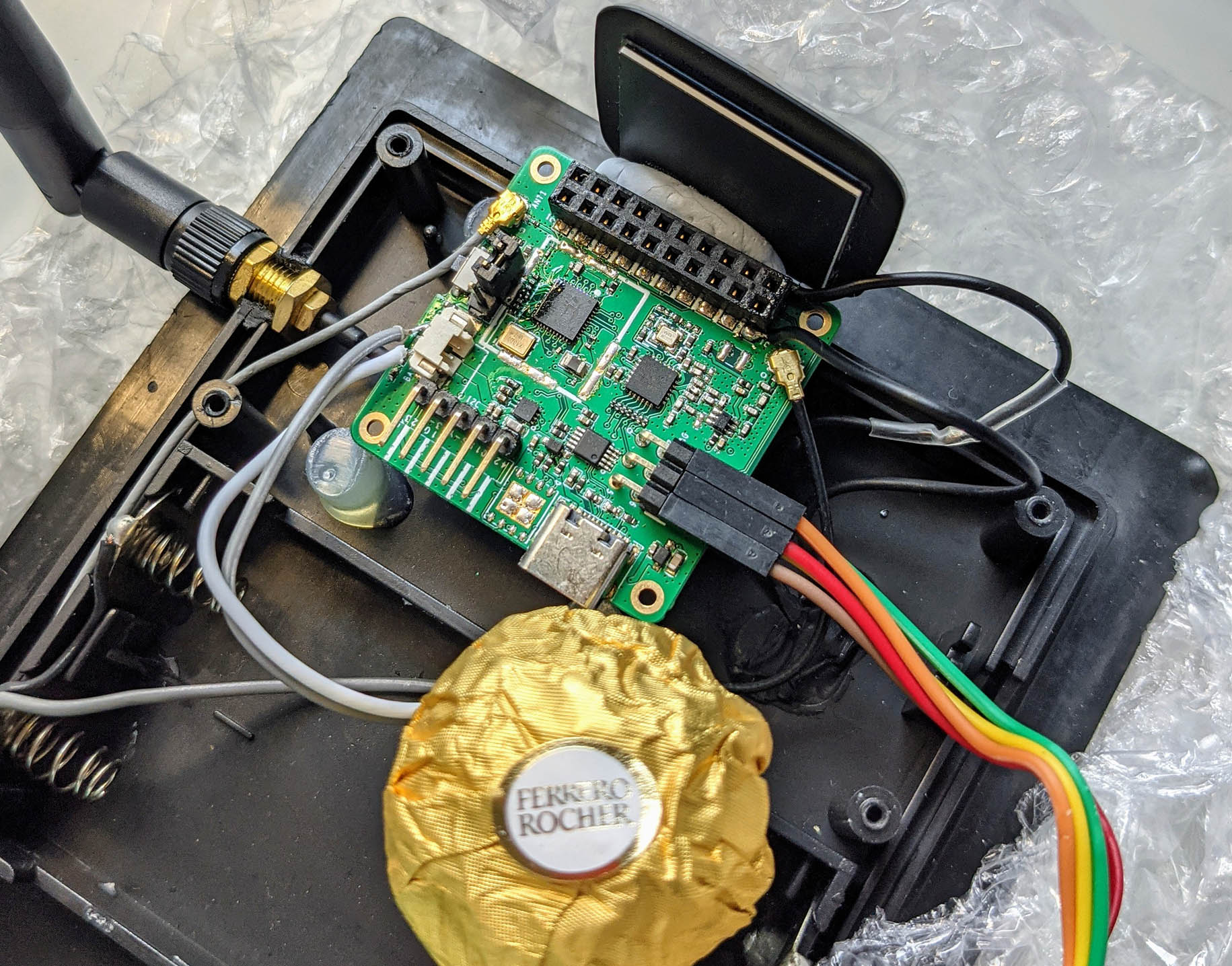
This article describes the (pre-production) PineDio Stack Prototype thus…
⚠️ Obligatory Disclaimer: Features included in The Prototype are not complete, and will most certainly undergo changes before becoming available for public consumption. (Burp) They are described here for testing, exploration, education and entertainment purposes only. The Prototype shall NOT be used in production gadgets. (Like toasters, microwave ovens, and most definitely not, pressure cookers)
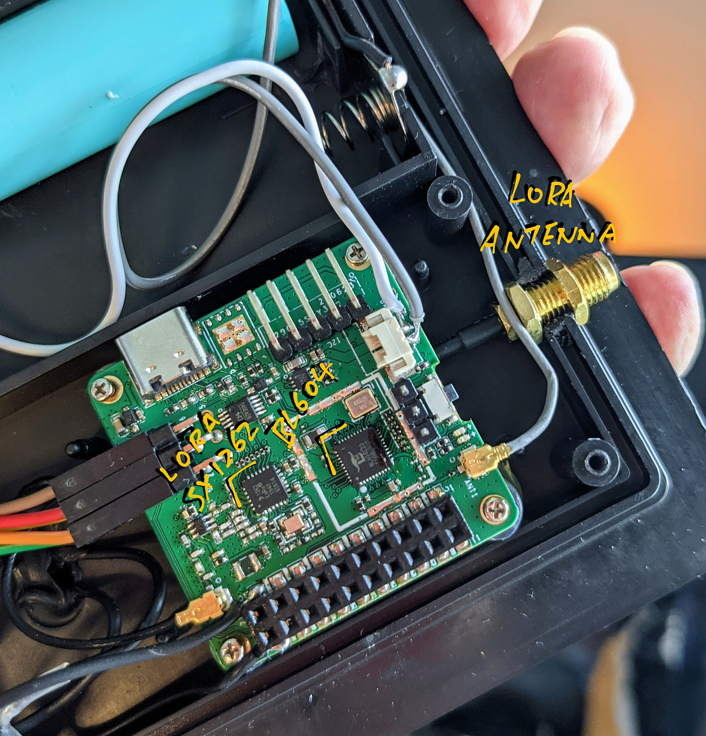
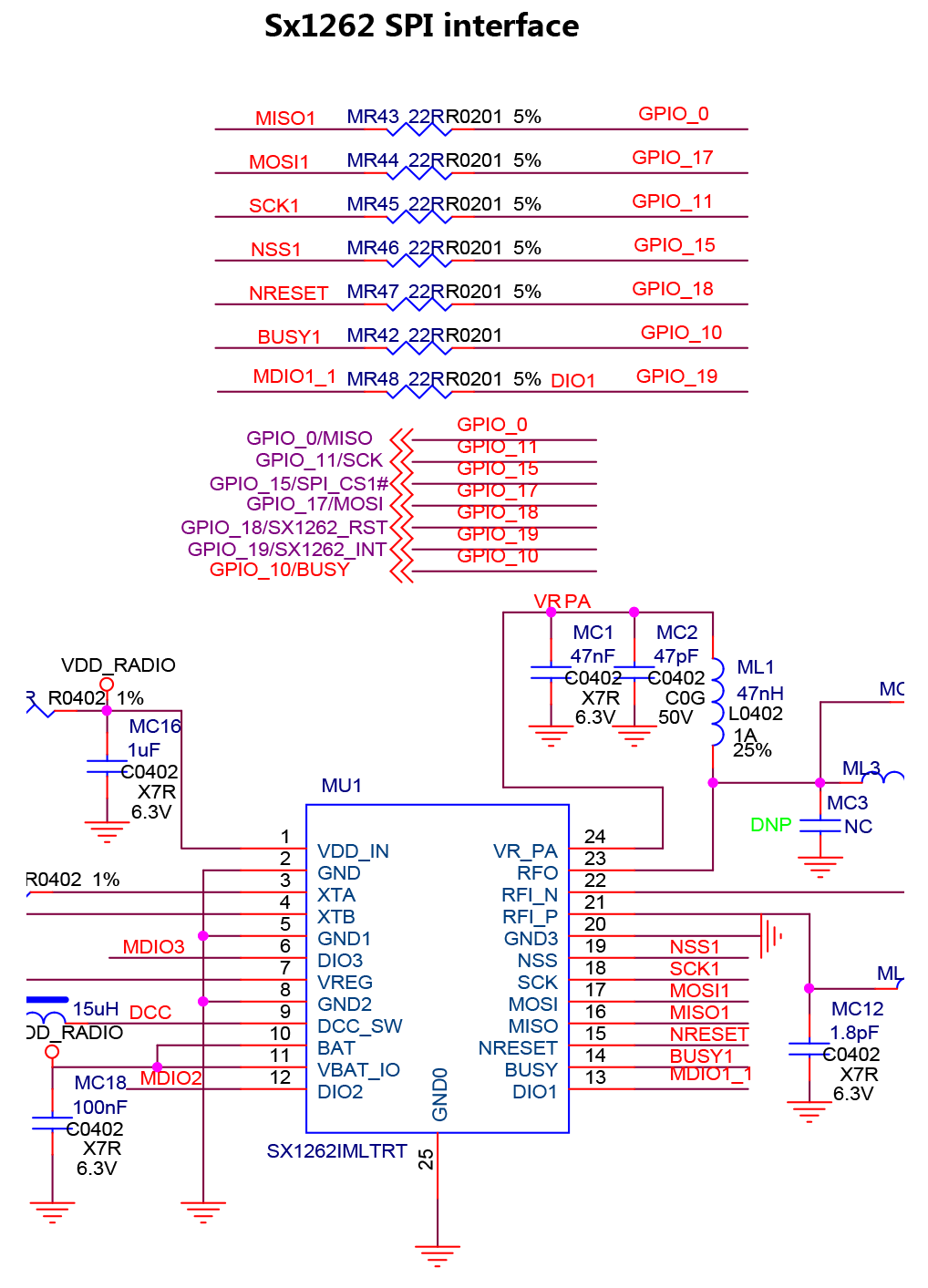
According to the PineDio Stack Schematic…
Our LoRa SX1262 Transceiver is wired onboard like so…
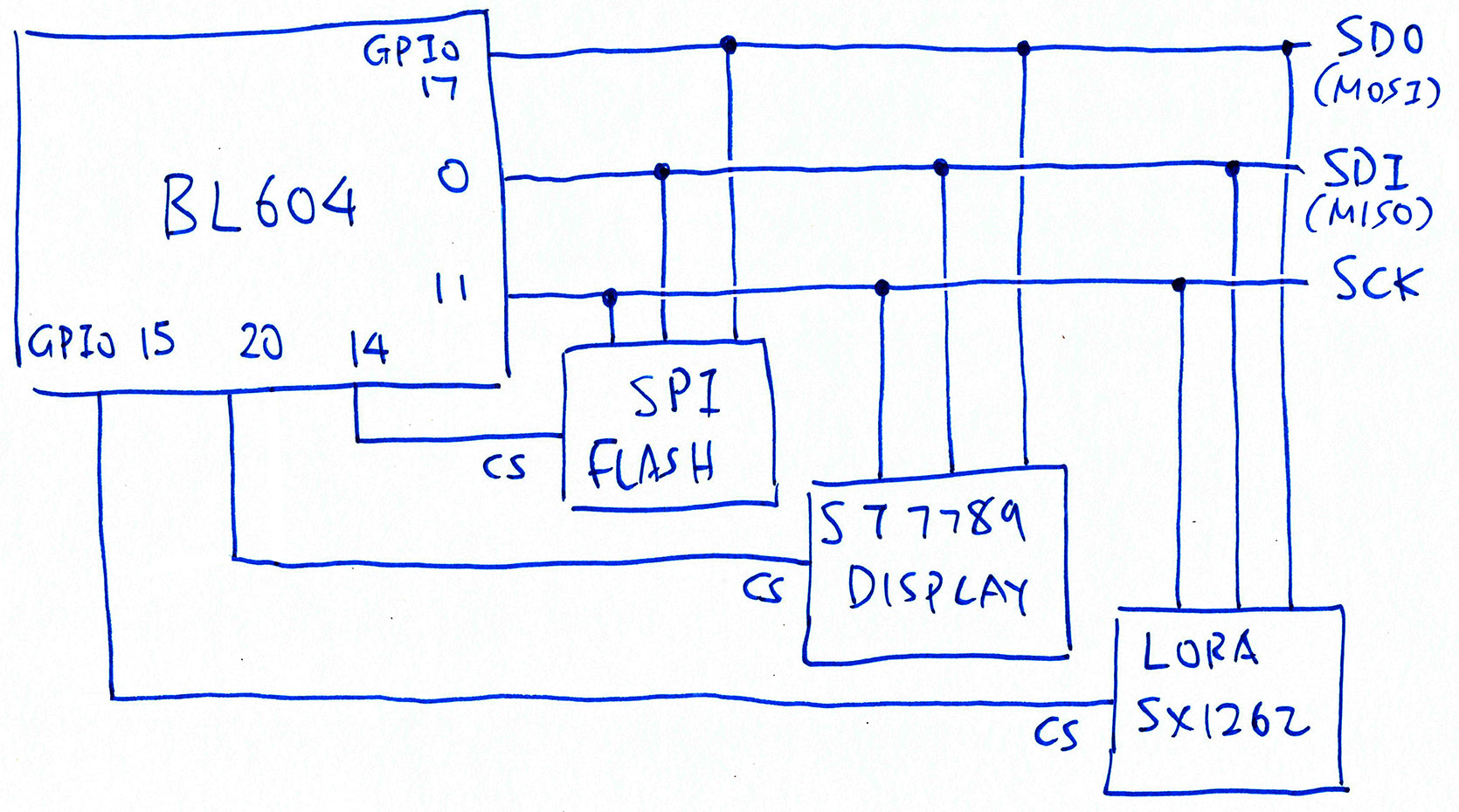
Note that the above SPI Pins are shared with the SPI Flash and ST7789 Display…
| GPIO Number | SPI Pin |
|---|---|
17 | Common SDO (MOSI) |
0 | Common SDI (MISO) |
11 | Common SCK |
14 | CS for SPI Flash |
20 | CS for ST7789 |
15 | CS for SX1262 |
We set the Chip Select Pin (CS) to Low to select the Active SPI Device: Either LoRa SX1262, SPI Flash or ST7789 Display…
To test the LoRa SX1262 Transceiver, we define the GPIO Pin Numbers like so: lora-sx1262/sx126x-board.h
//  Below are the pin numbers for PineDio Stack BL604 with onboard SX1262.
#define SX126X_SPI_IDX           0  //  SPI Port 0
#define SX126X_SPI_SDI_PIN       0  //  SPI Serial Data In Pin  (formerly MISO)
#define SX126X_SPI_SDO_PIN      17  //  SPI Serial Data Out Pin (formerly MOSI)
#define SX126X_SPI_CLK_PIN      11  //  SPI Clock Pin
#define SX126X_SPI_CS_PIN       15  //  SPI Chip Select Pin
#define SX126X_SPI_CS_OLD        8  //  Unused SPI Chip Select Pin
#define SX126X_NRESET           18  //  Reset Pin
#define SX126X_DIO1             19  //  DIO1
#define SX126X_BUSY_PIN         10  //  Busy Pin
#define SX126X_DEBUG_CS_PIN      5  //  Debug Chip Select Pin, mirrors the High / Low State of SX1262 Chip Select Pin. Set to -1 if not needed.
#define SX126X_TCXO_WAKEUP_TIME  5  //  Time required for the TCXO to wakeup (milliseconds)
#define SX126X_SPI_BAUDRATE (200 * 1000) // SPI Frequency (200 kHz)(SX126X_DEBUG_CS_PIN should be set to -1 if we’re not debugging. More about the Debug CS Pin later)
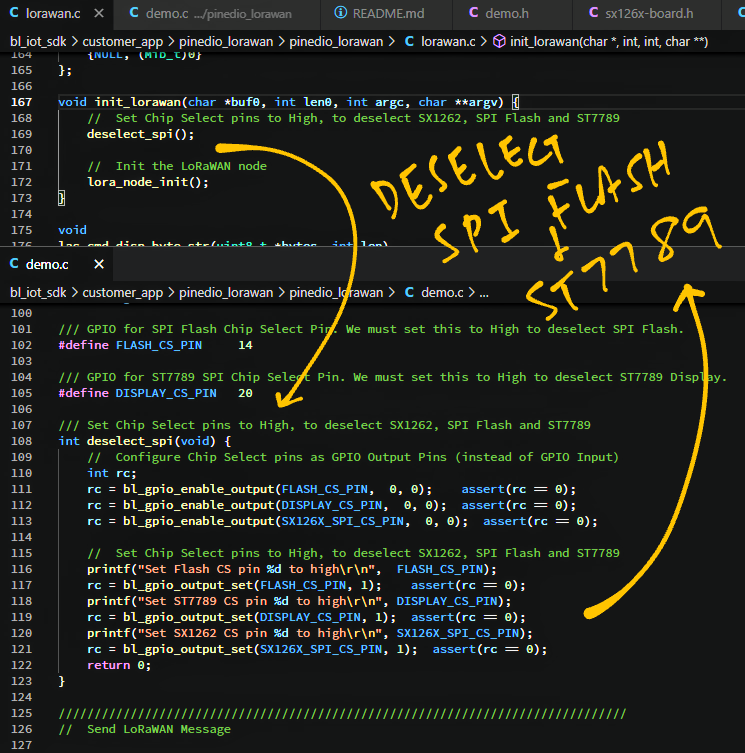
We define the Chip Select Pins for SPI Flash and ST7789 Display as well: pinedio_lorawan/demo.c
/// GPIO for SPI Flash Chip Select Pin. We must set this to High to deselect SPI Flash.
#define FLASH_CS_PIN     14

/// GPIO for ST7789 SPI Chip Select Pin. We must set this to High to deselect ST7789 Display.
#define DISPLAY_CS_PIN 20To test LoRaWAN on PineDio Stack we shall run this LoRaWAN Firmware…
Which calls the following LoRaWAN and SX1262 Drivers…
The firmware and drivers were previously ported from Apache Mynewt operating system to BL602 and BL604…
Here are the changes we made for PineDio Stack.
While testing LoRaWAN (and LoRa SX1262), we need to deselect all other SPI Peripherals (SPI Flash and ST7789 Display).
From pinedio_lorawan/demo.c …
/// Set Chip Select pins to High, to deselect SX1262, SPI Flash and ST7789
int deselect_spi(void) {
  //  Configure Chip Select pins as GPIO Output Pins (instead of GPIO Input)
  int rc;
  rc = bl_gpio_enable_output(FLASH_CS_PIN,      0, 0);  assert(rc == 0);
  rc = bl_gpio_enable_output(DISPLAY_CS_PIN,    0, 0);  assert(rc == 0);
  rc = bl_gpio_enable_output(SX126X_SPI_CS_PIN, 0, 0);  assert(rc == 0);
  if (SX126X_DEBUG_CS_PIN >= 0) {  //  Mirror SX126X_SPI_CS_PIN
    rc = bl_gpio_enable_output(SX126X_DEBUG_CS_PIN, 0, 0);  assert(rc == 0);
  }
First we configure the Chip Select Pins for GPIO Output.
Then we set the Chip Select Pins to High, to deselect the SPI Peripherals…
  //  Set Chip Select pins to High, to deselect SX1262, SPI Flash and ST7789
  rc = bl_gpio_output_set(FLASH_CS_PIN,      1);  assert(rc == 0);
  rc = bl_gpio_output_set(DISPLAY_CS_PIN,    1);  assert(rc == 0);
  rc = bl_gpio_output_set(SX126X_SPI_CS_PIN, 1);  assert(rc == 0);
  if (SX126X_DEBUG_CS_PIN >= 0) {  //  Mirror SX126X_SPI_CS_PIN
    rc = bl_gpio_output_set(SX126X_DEBUG_CS_PIN, 1);  assert(rc == 0);
  }
  return 0;
}
(More about SX126X_DEBUG_CS_PIN when we talk about the Logic Analyser)
This function is called by the init_lorawan Command, which we’ll run in a while…
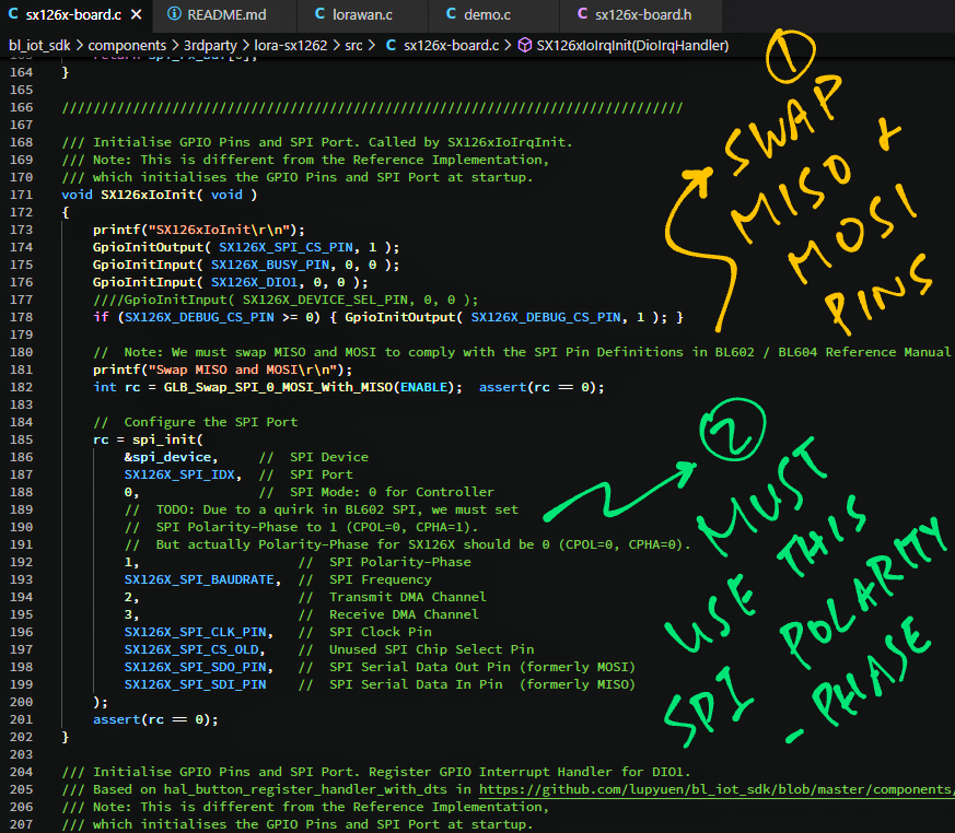
Due to a quirk in the SPI implementation on BL602 and BL604, we need to swap the SPI Pins for SDI (formerly MISO) and SDO (formerly MOSI).
We do this by calling GLB_Swap_SPI_0_MOSI_With_MISO in lora-sx1262/sx126x-board.c …
/// Initialise GPIO Pins and SPI Port. Called by SX126xIoIrqInit.
void SX126xIoInit( void ) {
  //  Configure the pins for GPIO Input / Output
  GpioInitOutput( SX126X_SPI_CS_PIN, 1 );
  GpioInitInput( SX126X_BUSY_PIN, 0, 0 );
  GpioInitInput( SX126X_DIO1, 0, 0 );
  if (SX126X_DEBUG_CS_PIN >= 0) { GpioInitOutput( SX126X_DEBUG_CS_PIN, 1 ); }

  //  Note: We must swap SDI (MISO) and SDO (MOSI)
  //  to comply with the SPI Pin Definitions in
  //  BL602 / BL604 Reference Manual
  int rc = GLB_Swap_SPI_0_MOSI_With_MISO(ENABLE);  assert(rc == 0);
(More about swapping SPI Pins)
After swapping the SPI Pins we may initialise the SPI Port…
  //  Configure the SPI Port
  rc = spi_init(
    &spi_device,     //  SPI Device
    SX126X_SPI_IDX,  //  SPI Port
    0,               //  SPI Mode: 0 for Controller
    //  TODO: Due to a quirk in BL602 SPI, we must set
    //  SPI Polarity-Phase to 1 (CPOL=0, CPHA=1).
    //  But actually Polarity-Phase for SX126X should be 0 (CPOL=0, CPHA=0).
    1,                    //  SPI Polarity-Phase
    SX126X_SPI_BAUDRATE,  //  SPI Frequency
    2,                    //  Transmit DMA Channel
    3,                    //  Receive DMA Channel
    SX126X_SPI_CLK_PIN,   //  SPI Clock Pin
    SX126X_SPI_CS_OLD,    //  Unused SPI Chip Select Pin
    SX126X_SPI_SDO_PIN,   //  SPI Serial Data Out Pin (formerly MOSI)
    SX126X_SPI_SDI_PIN    //  SPI Serial Data In Pin  (formerly MISO)
  );
  assert(rc == 0);
}
Note that the SPI Polarity-Phase should be 1 and not 0.
This seems to be another quirk of the SPI implementation on BL602 and BL604…
We build, flash and run the LoRaWAN Firmware for PineDio Stack with these steps…
Now we enter the LoRaWAN commands to…
Join a LoRaWAN Network
(Because we’ll transmit data securely over LoRa)
Send a Data Packet to the network
(So that the packet appears in our LoRaWAN Gateway)
We’ll talk to the ChirpStack LoRaWAN Gateway that we have installed here…
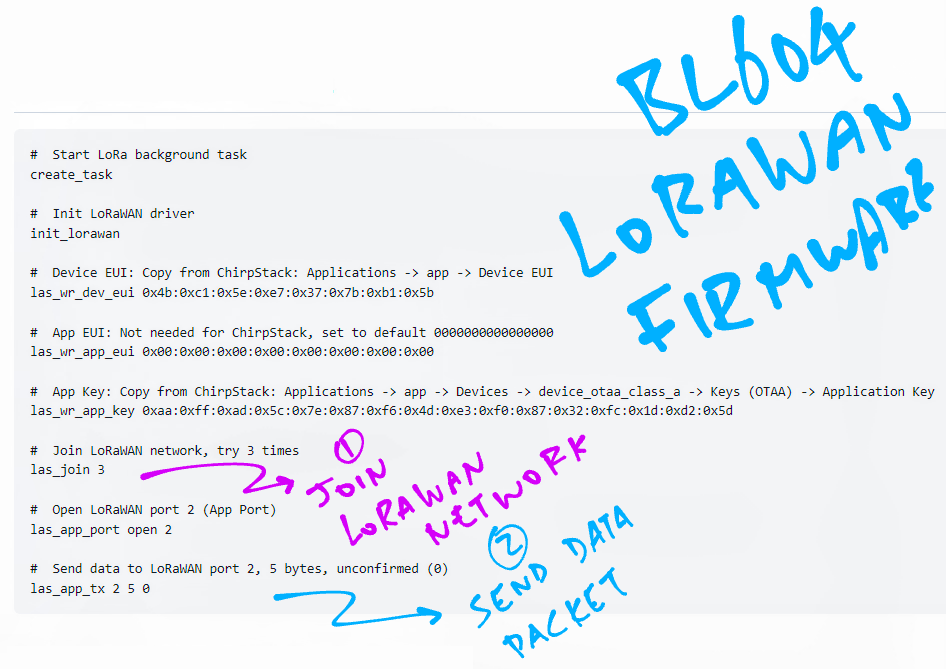
At the BL604 Command Prompt, enter these LoRaWAN Commands…
First we start the Background Task that will handle LoRa packets…
create_taskNext we initialise the LoRa SX1262 and LoRaWAN Drivers…
init_lorawanWe set the Device EUI (Extended Unique Identifier)…
las_wr_dev_eui 0x4b:0xc1:0x5e:0xe7:0x37:0x7b:0xb1:0x5bChange the above EUI to the one in our ChirpStack Gateway: Applications → app → Device EUI
Set the App EUI…
las_wr_app_eui 0x00:0x00:0x00:0x00:0x00:0x00:0x00:0x00This is not needed for ChirpStack, thus we set to default 0000000000000000.
Set the App Key…
las_wr_app_key 0xaa:0xff:0xad:0x5c:0x7e:0x87:0xf6:0x4d:0xe3:0xf0:0x87:0x32:0xfc:0x1d:0xd2:0x5dWe get the App Key from ChirpStack at Applications → app → Devices → device_otaa_class_a → Keys (OTAA) → Application Key
We send a request to join the LoRaWAN Network…
las_join 3(Retry up to 3 times)
After the ChirpStack LoRaWAN Gateway has accepted our Join Request, we open a LoRaWAN Application Port…
las_app_port open 2(2 is the Application Port Number)
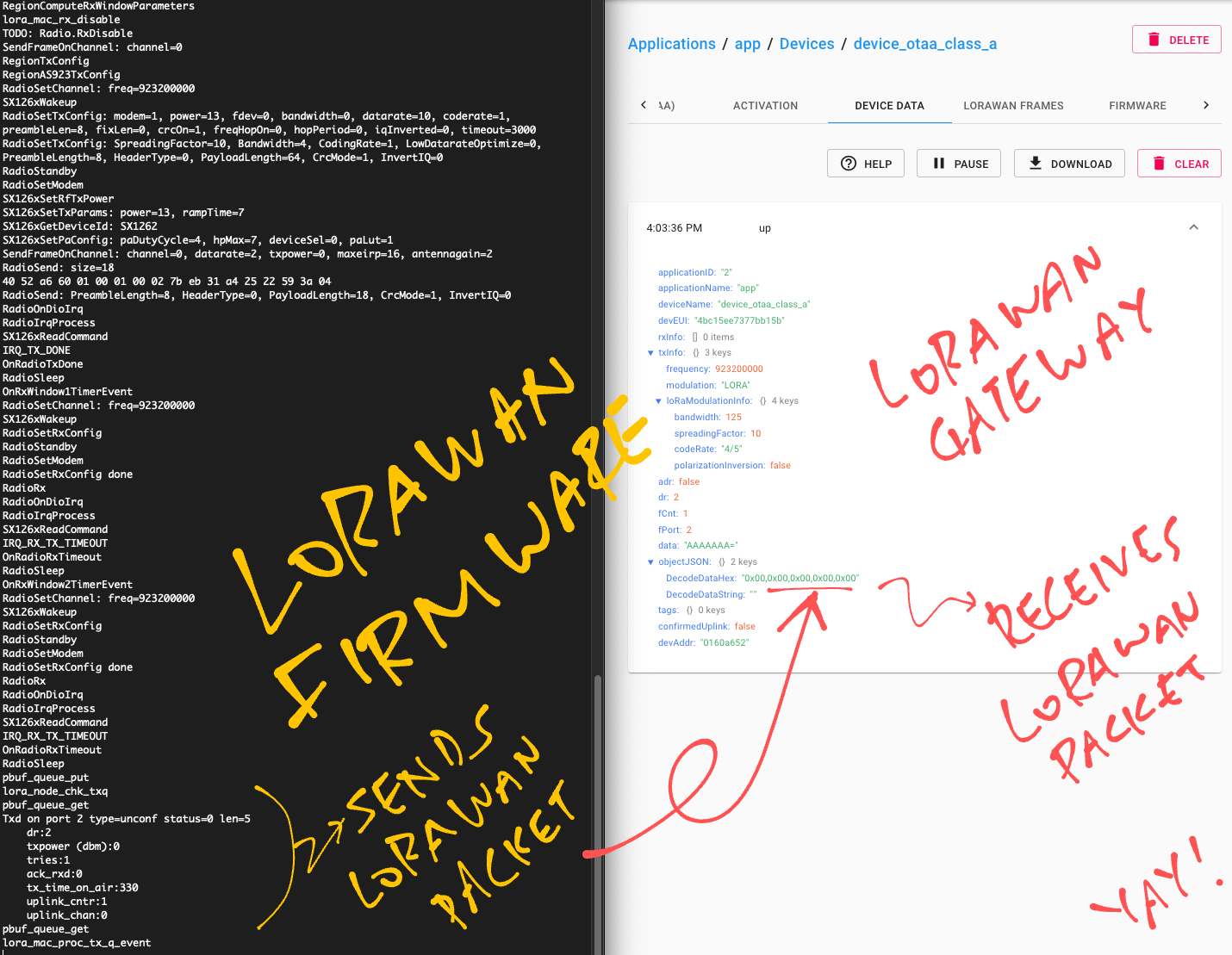
Finally we send a LoRaWAN Data Packet containing 5 bytes of data (0x00) to LoRaWAN Port 2…
las_app_tx 2 5 0(0 means that this is an Unconfirmed Message, we’re not expecting an acknowledgement from the LoRaWAN Gateway)
We should see this in our PineDio Stack serial terminal…
Let’s check our ChirpStack LoRaWAN Gateway!
(More about the LoRaWAN Commands)
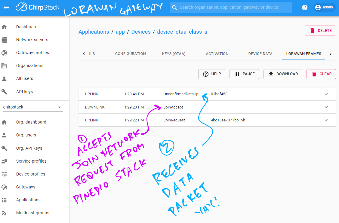
To see the Join Network Request and the Data Packet received by our ChirpStack LoRaWAN Gateway, we do this…
In ChirpStack, click Applications → app → device_otaa_class_a → LoRaWAN Frames
Restart PineDio Stack.
Run the LoRaWAN Commands from the previous section.
The Join Network Request appears in ChirpStack, followed by the Data Packet…
Click the Device Data tab in ChirpStack.
On PineDio Stack, run this command to send a Data Packet…
las_app_tx 2 5 0Our Data Packet appears in ChirpStack.
DecodedDataHex shows 5 bytes of zero, which is what we sent…
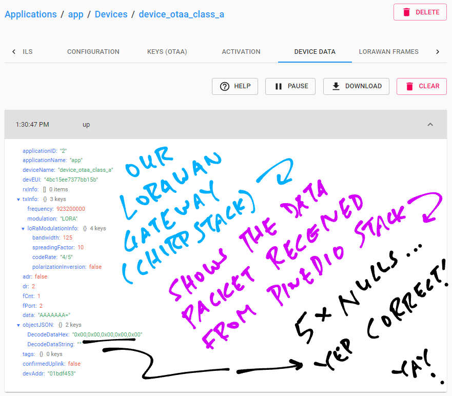
LoRaWAN tested OK on PineDio Stack!
Let’s take a peek inside our LoRa SX1262 Transceiver…
How did we find out that the SPI Pins need to be swapped?
And the tweaking for SPI Polarity-Phase?
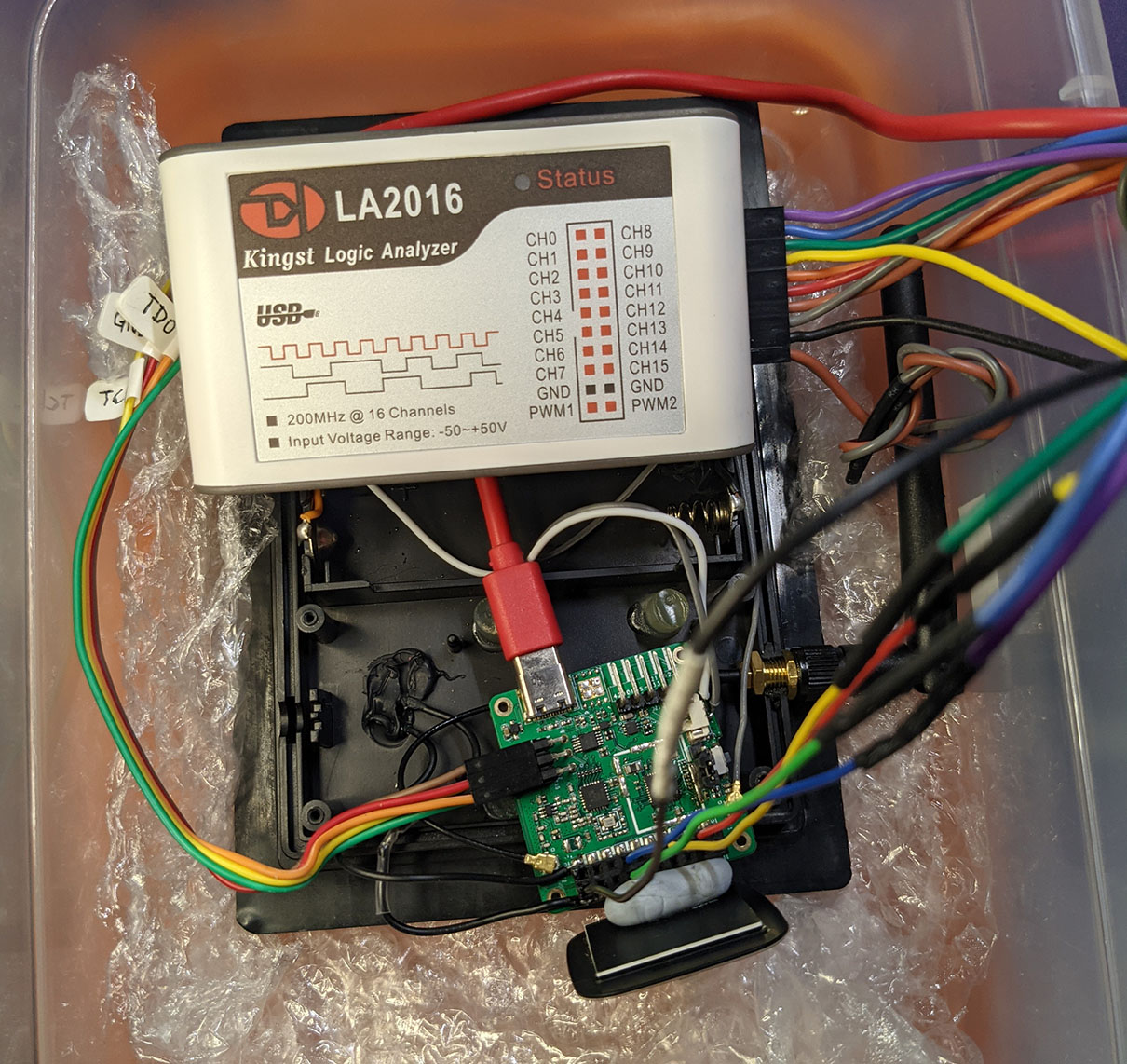
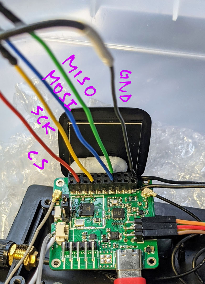
A Logic Analyser is super helpful for troubleshooting SPI and other interfacing problems on prototype hardware. (Pic above)
PineDio Stack’s GPIO Connector exposes the SPI Pins: SDO (formerly MOSI), SDI (formerly MISO) and SCK…
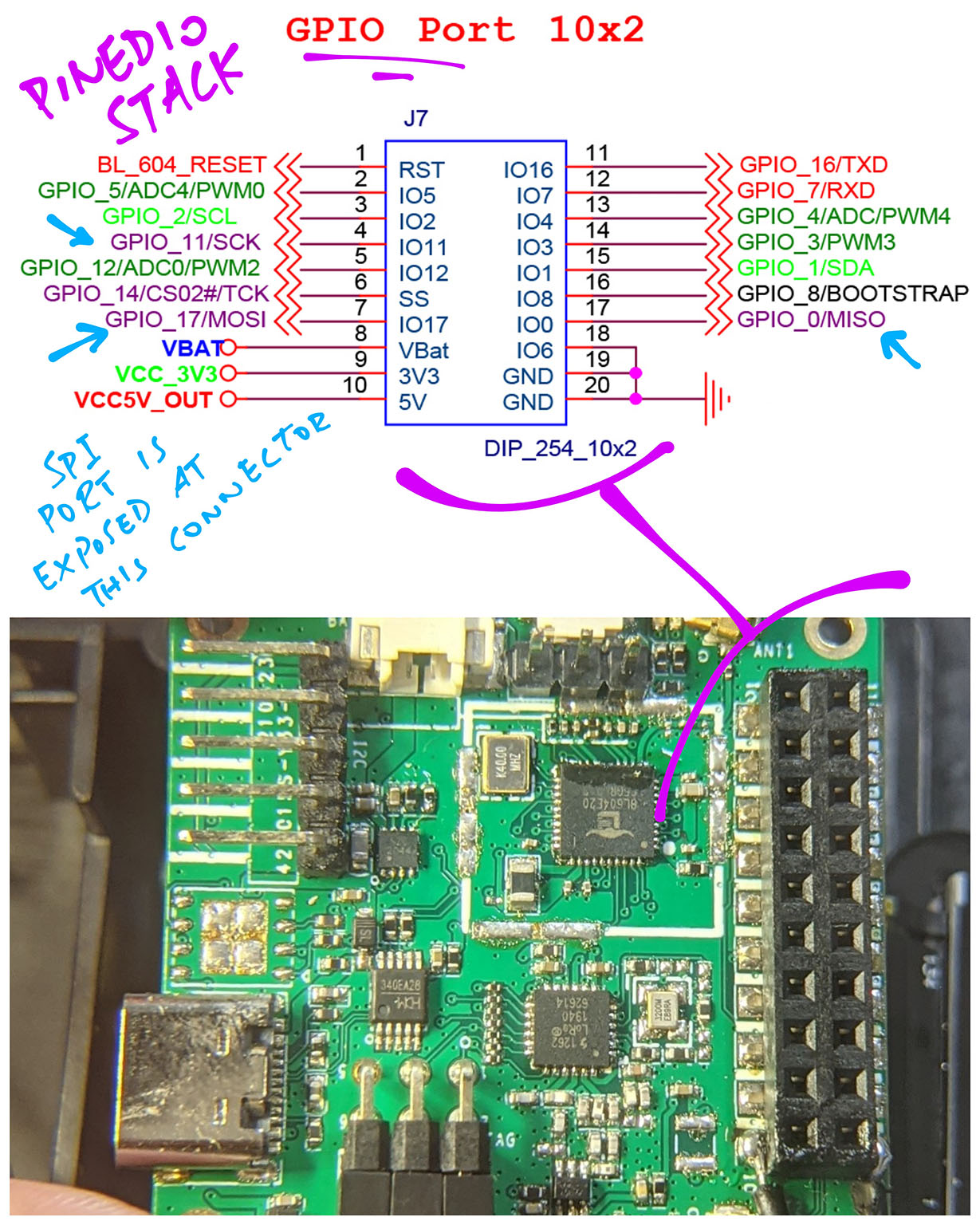
We connect our Logic Analyser to the GPIO Connector like so…
| GPIO Number | SPI Pin | Connector Pin |
|---|---|---|
17 | Common SDO (MOSI) | 7 |
0 | Common SDI (MISO) | 17 |
11 | Common SCK | 4 |
5 | Debug CS | 2 |
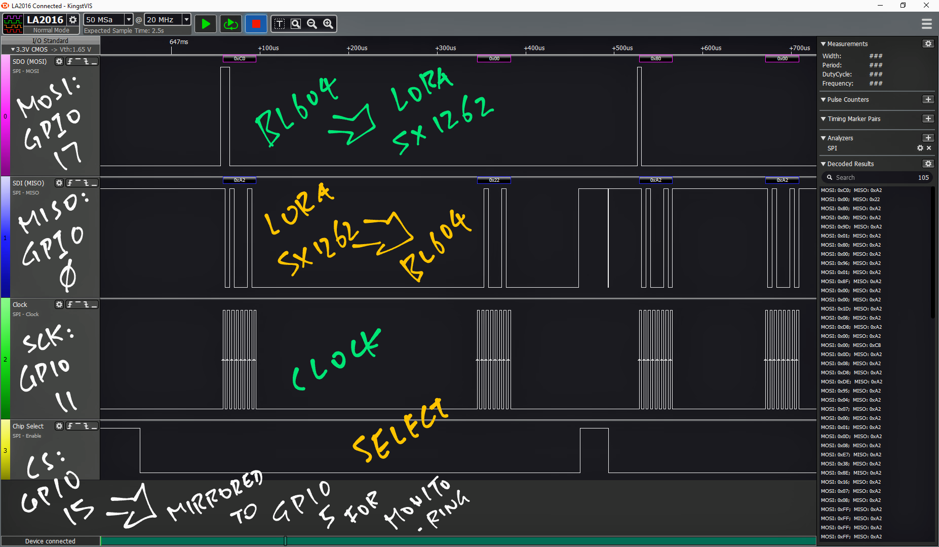
What about the SX1262 Chip Select Pin: GPIO 15?
Unfortunately GPIO 15 is not exposed on the GPIO Connector.
Hence we designate GPIO 5 as the Debug CS Pin that mirrors the GPIO High / Low state of GPIO 15. (Here’s how)
Then we simply connect our Logic Analyser to GPIO 5 as the Chip Select Pin. (Pic above)
Our Logic Analyser shows that BL604 is indeed talking correctly to SX1262 over SPI…
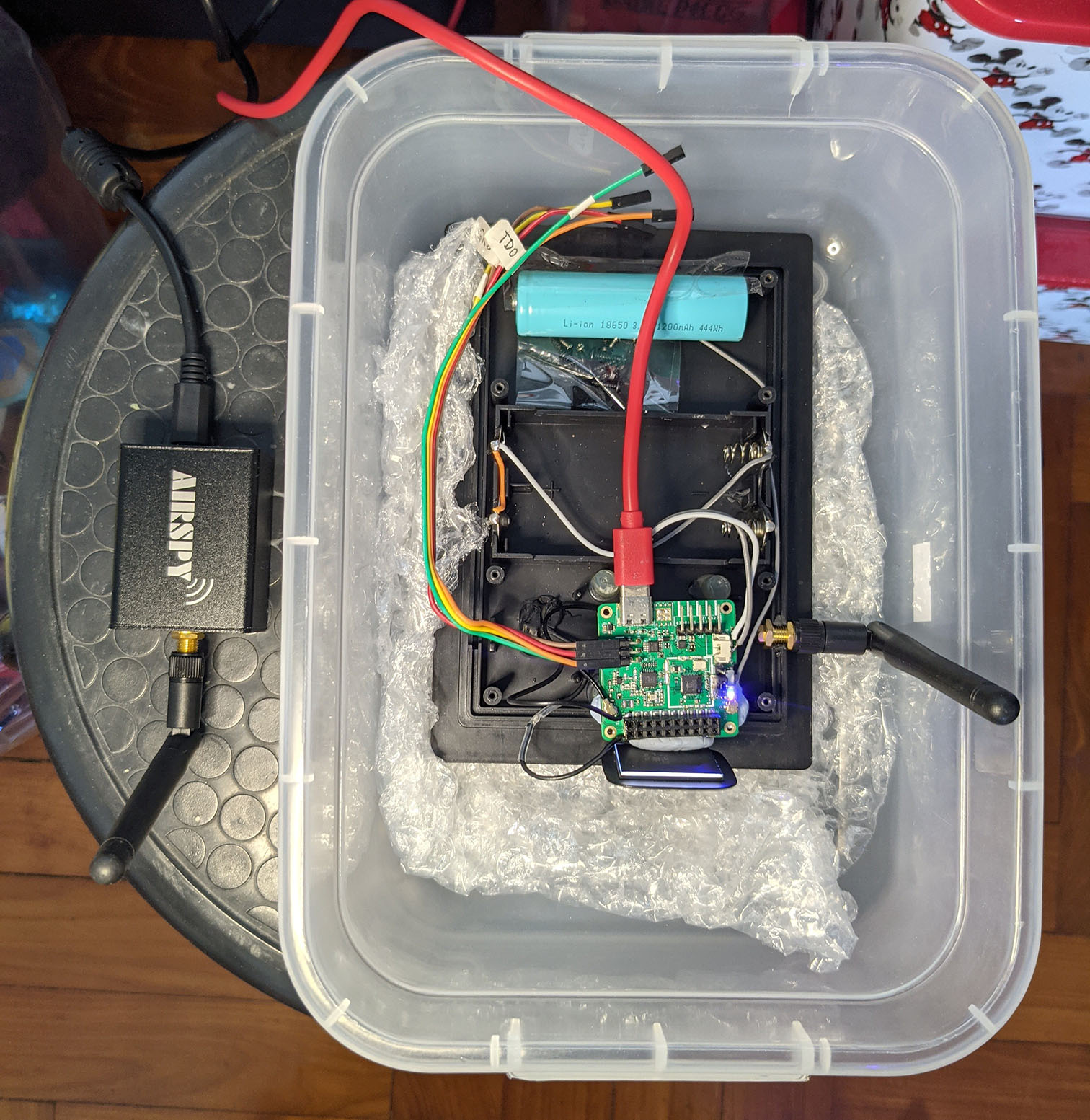
We’ve used a Logic Analyser to sniff the data inside our LoRa Transceiver. Now we use a Spectrum Analyser to sniff the data in the airwaves!
Our Spectrum Analyser is the Airspy R2 Software Defined Radio, which will sniff a range of radio frequences…
When we analyse the radio spectrum (with Cubic SDR), we see this healthy radio signal produced by our LoRa Transceiver…
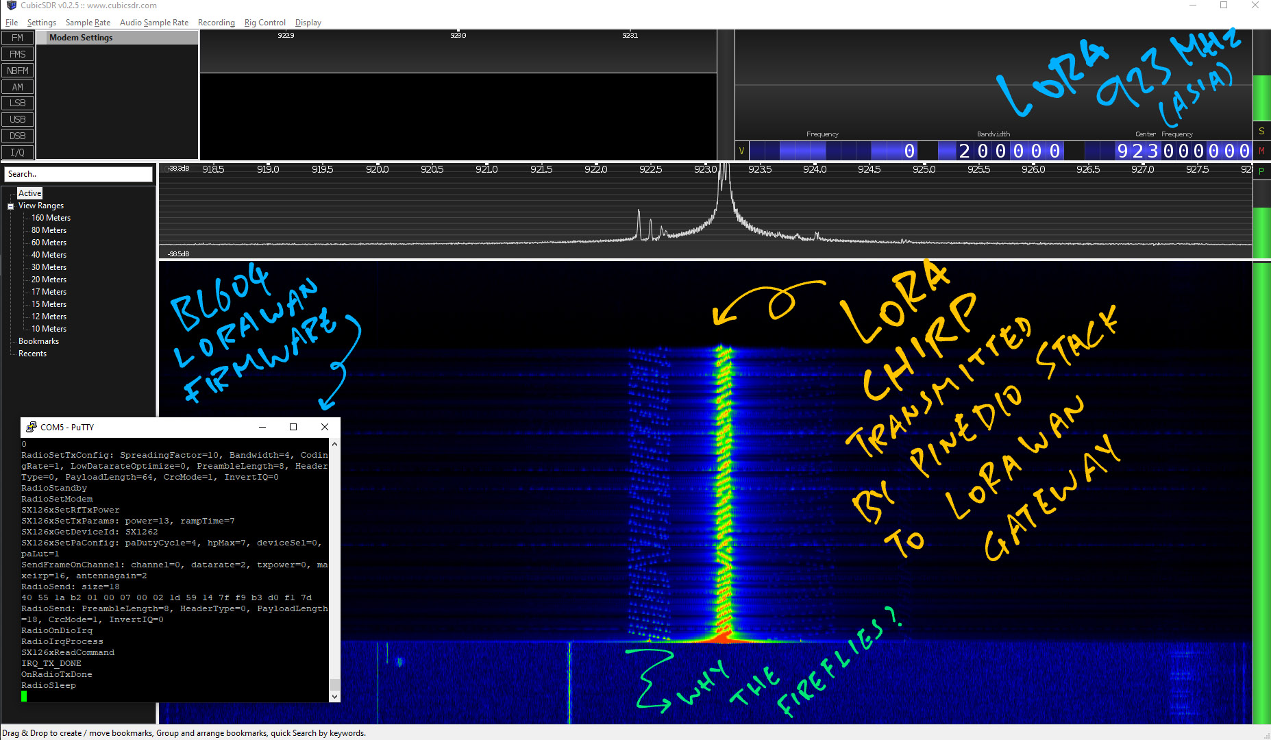
This is known as a LoRa Chirp.
LoRa Packets have this unique shape so that the packets can be transmitted over long distances in spite of radio interference.
(Up to 5 kilometres in some urban areas!)
More about LoRa and Software Defined Radio here…
(The “fireflies” look odd though. Are we transmitting with too much power?)
Since LoRa packets can be sniffed over the airwaves…
How do we transmit data securely over LoRa?
That’s why we join a LoRaWAN Network when we transmit data.
LoRaWAN is a layer on top of LoRa that adds security features like…
Message Encryption
(Messages are encrypted with a 128-bit AES Key)
Message Integrity Check
(Prevents tampering and replay of messages)
Message Routing
(We relay messages through a trusted LoRaWAN Gateway, instead of peer-to-peer direct messaging)
Message Throttling
(Prevents flooding of messages)
More about LoRaWAN Security here…
What’s the catch?
Well the LoRaWAN Security Keys would need to be stored and accessed securely on PineDio Stack.
We should never allow the Security Keys to be exposed.
Doesn’t BL604 securely store Security Keys in its Internal EFuse Storage?
Yes. Though there have been past incidents (on other microcontrollers) where Security Keys in EFuse Storage have been compromised. (See this)
Is there a better way to store and access Security Keys?
We could use a Cryptographic Co-Processor like this…
ATECC608A works with The Things Network, the public worldwide LoRaWAN Network…
It also works with Helium, another global LoRaWAN Network…
There are new dev boards with ATECC608 onboard…
This article explains how a microcontroller might connect to a secure network (like LoRaWAN) with ATECC608A…
What’s the catch?
We need to be extra careful when working with Cryptographic Co-Processors…
Once the Security Keys have been injected, they can never be reset!
(Same for EFuse Storage)
Can we send LoRa messages securely… Without LoRaWAN?
Traditional Peer-to-Peer Messaging Protocols (like XMPP and Matrix) won’t run on PineDio Stack with LoRa.
(Because of LoRa’s tiny lossy packets. And JSON over HTTPS is too heavy for BL604)
These newer Peer-to-Peer Messaging Protocols will probably work with PineDio Stack…
Meshtastic: Data Mesh Network for LoRa
QMesh: Voice Mesh Network for LoRa
Mycelium Mesh: Text Mesh Network for LoRa
There is an experimental Matrix protocol for IoT devices…
Maybe we’ll see messaging protocols based on Blockchain…
But how secure are they?
Calm down, amigo… Sorry I haven’t reviewed their security features.
Someday I might!
PineDio Stack supports triple comms: LoRa, WiFi AND Bluetooth LE…
What can we do with them?
Maybe we can turn PineDio Stack into a (very basic) Solar-Powered Gateway for LoRa + WiFi + Bluetooth LE?
That will relay LoRa and Bluetooth LE messages to the internet over WiFi?
Like for tracking our pets? (Excluding hamsters and goldfish)
Or for connecting our PineTime watches to the internet?
Perhaps super-accurate geolocation with LoRa + WiFi + Bluetooth LE?
Got any ideas? Lemme know!
I’m really excited that PineDio Stack BL604 will be available soon!
But in the meantime, JF and I have plenty to test on PineDio Stack…
Please let us know if you’re keen to help! 🙏
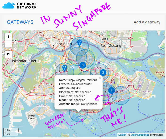
In the next article, PineDio Stack shall transmit data to the cloud via the public global LoRaWAN Network… The Things Network!
(Sorry for griping… But why doesn’t Singapore have decent coverage for The Things Network? 🙄)
Got a question, comment or suggestion? Create an Issue or submit a Pull Request here…
lupyuen.github.io/src/lorawan2.md
This article is the expanded version of this Twitter Thread
Here’s a great way run a PineDio Stack BL604 Regression Test with GPIO, ADC, SPI, SX1262, LoRa, LoRaWAN and The Things Network
This is how we tested the upstream updates from Pine64’s BL602 IoT SDK before merging them. (See this)
However Bouffalo Lab’s BL602 IoT SDK has just been revamped with the new “hosal” HAL.
We have no plans yet to merge with the new HAL, because it will impact all the articles and code that we have written for “The RISC-V BL602 / BL604 Book”.
How shall we proceed? Lemme know what you think! 🙏