📝 13 Dec 2021
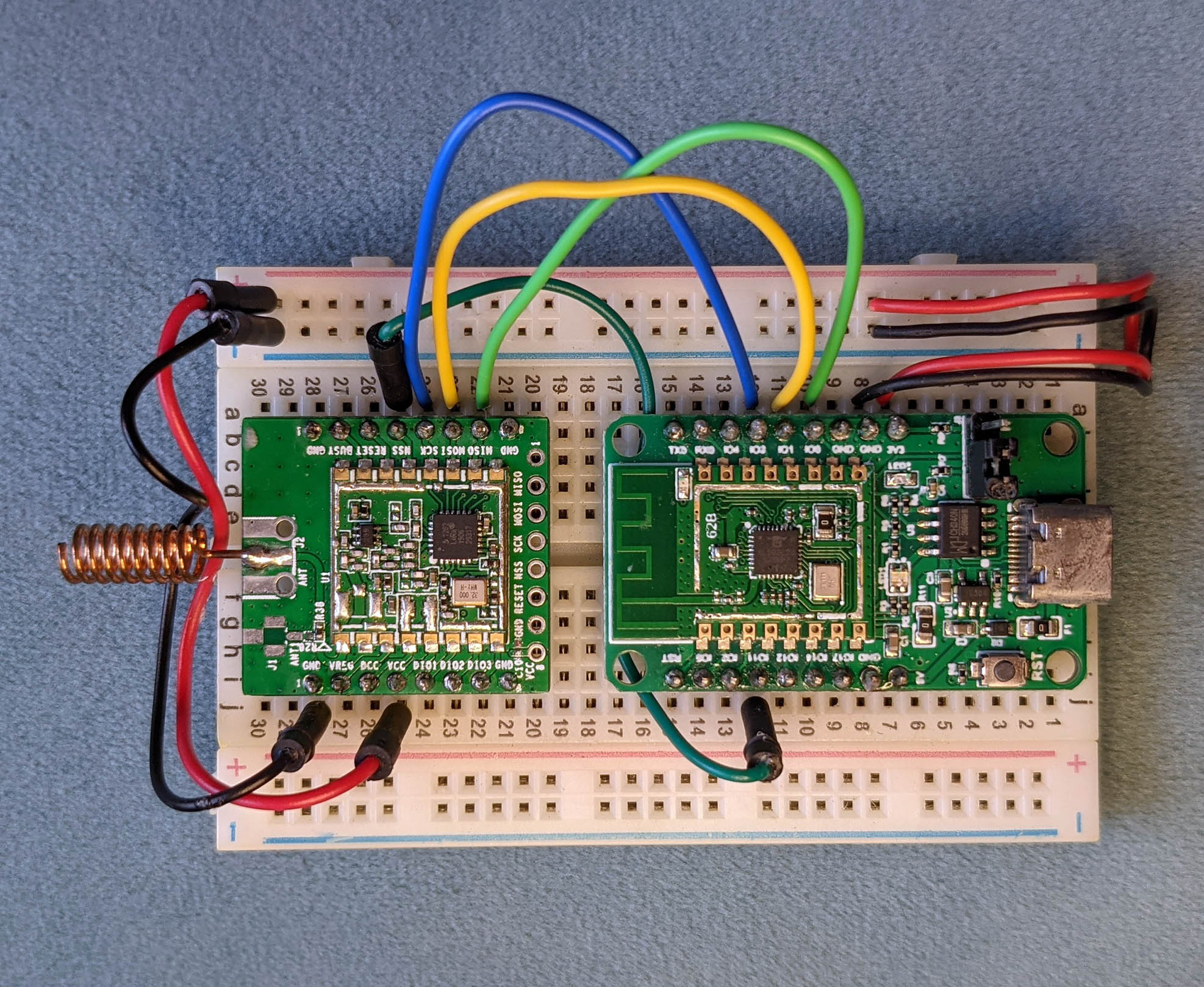
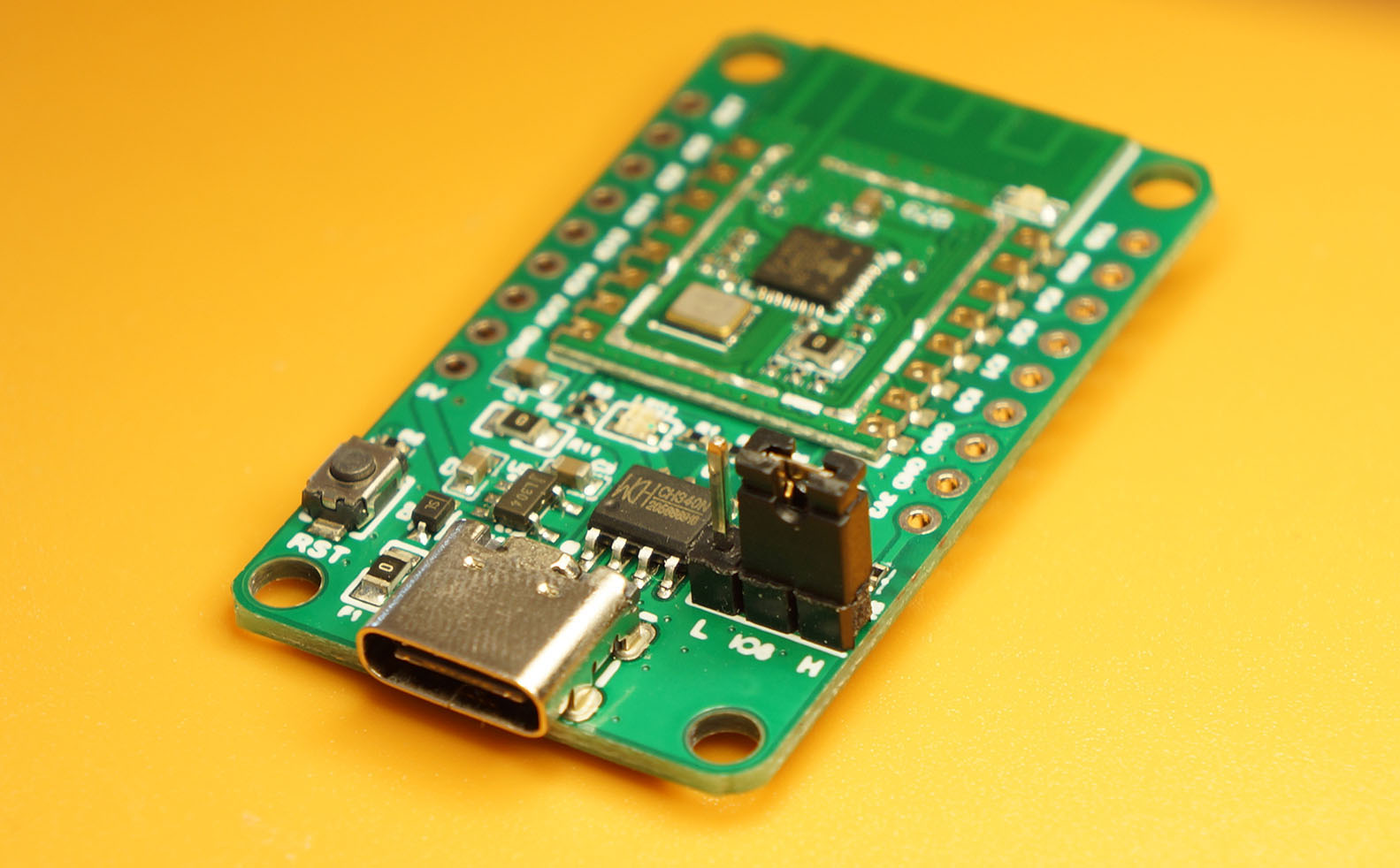
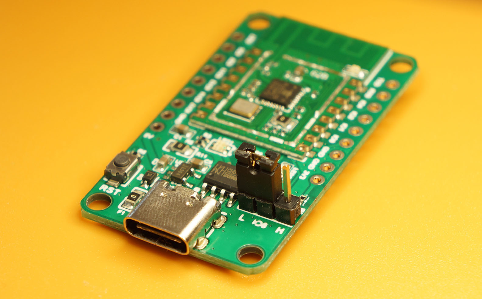
PineCone BL602 Board (right) connected to Semtech SX1262 LoRa Transceiver (left)
Last article we explored Apache NuttX OS and its GPIO Functions…
Today we shall venture into the SPI Functions and discover…
How to transmit and receive data over SPI
By coding a simple NuttX Device Driver
And testing with Semtech SX1262 (LoRa Transceiver)
On Bouffalo Lab’s BL602 and BL604 RISC-V SoCs
We’ll also study briefly the internals of the NuttX SPI Driver, to understand how it works.
What about ESP32? NuttX works the same across platforms right?
I realise that many of my readers are using ESP32 instead of BL602.
In this article I’ll point out the tweaks needed to run the code on ESP32.
(Watch for the “For ESP32” tags)
(For BL602 and ESP32)
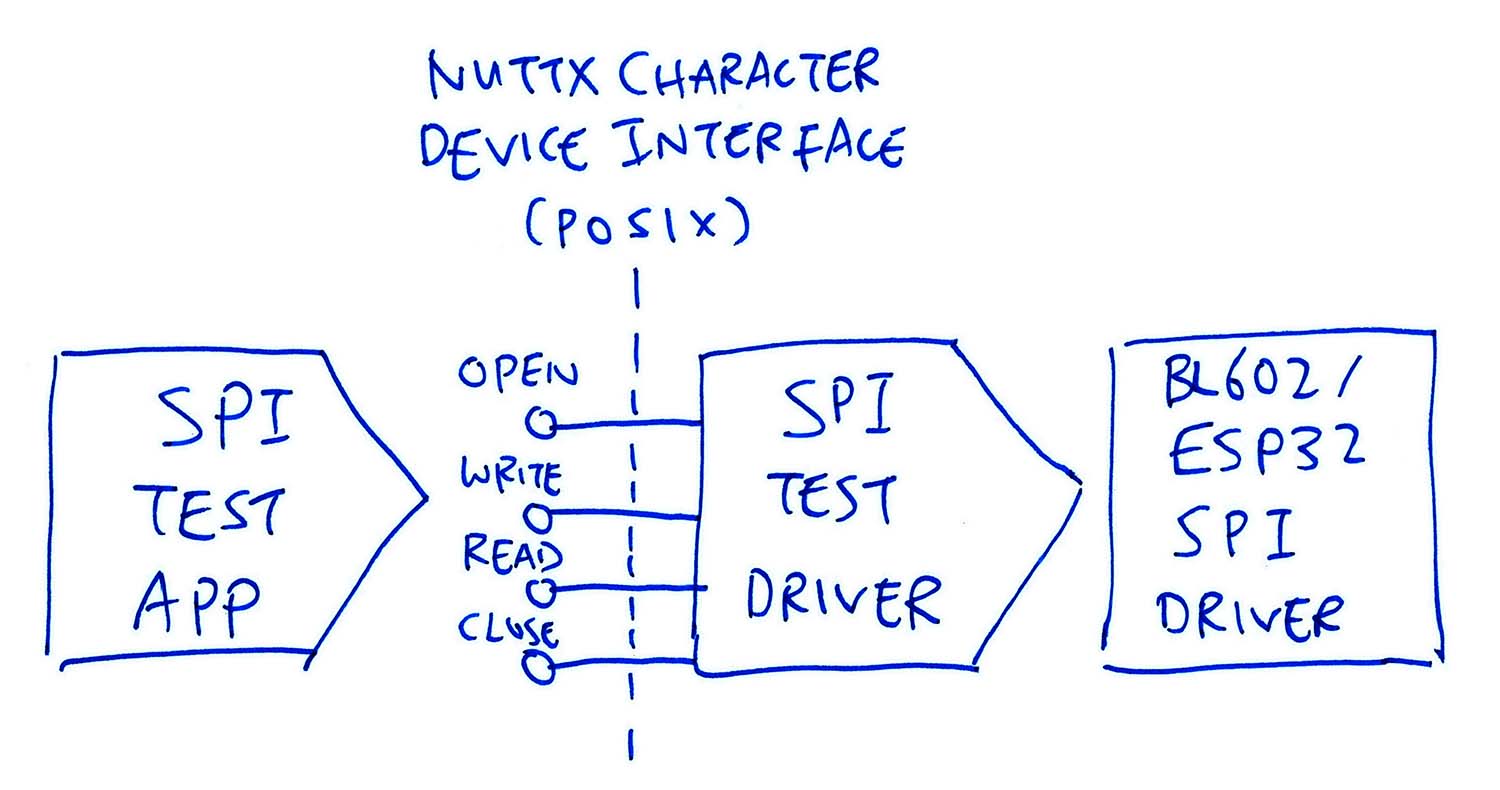
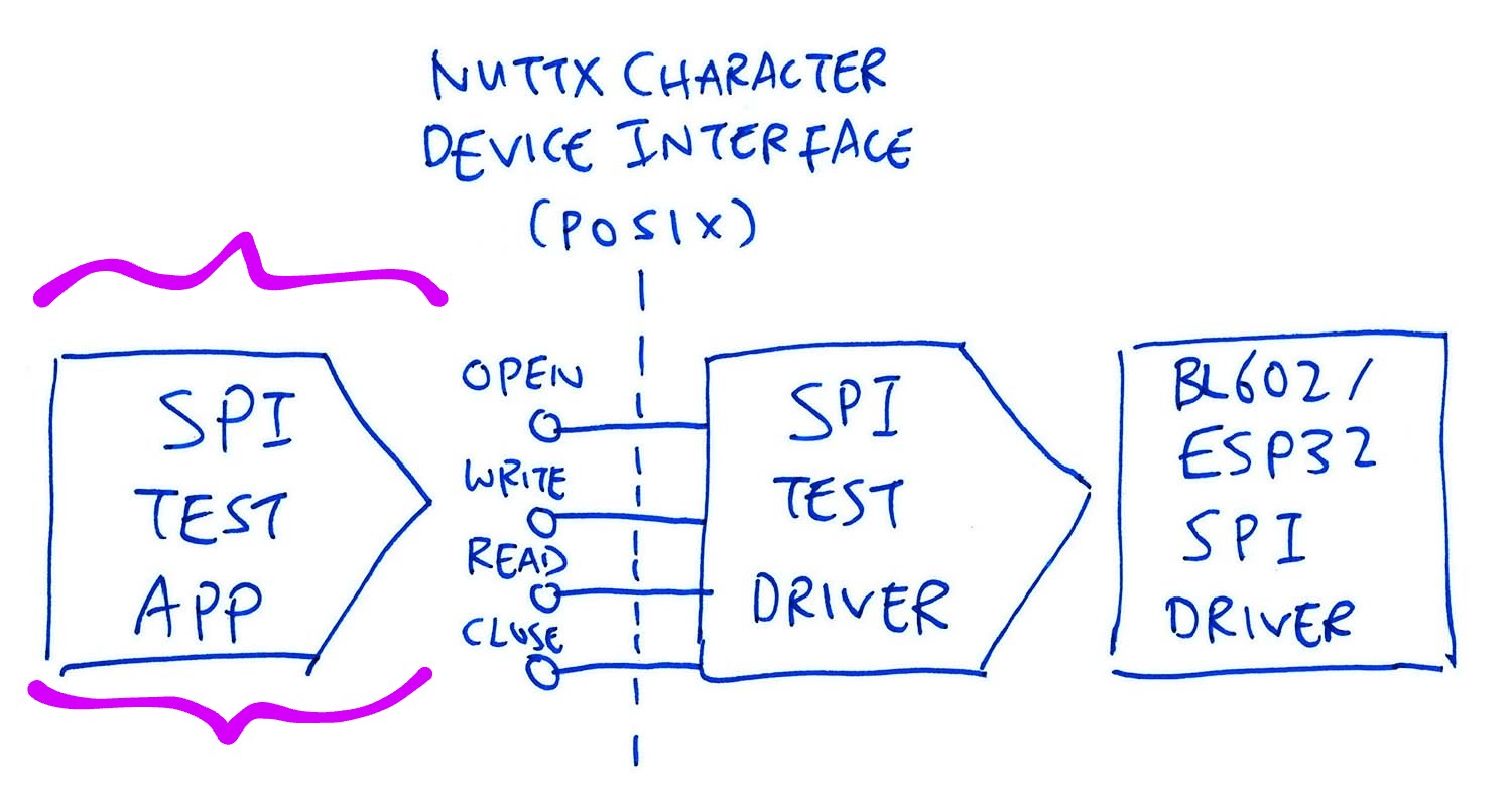
Our plan for today (pic above)…
We create an SPI Test App that will transfer data over SPI.
(A tiny program with a few lines of code)
We create an SPI Test Driver (called by SPI Test App) that will handle the SPI Operations.
(To transmit and receive data over SPI)
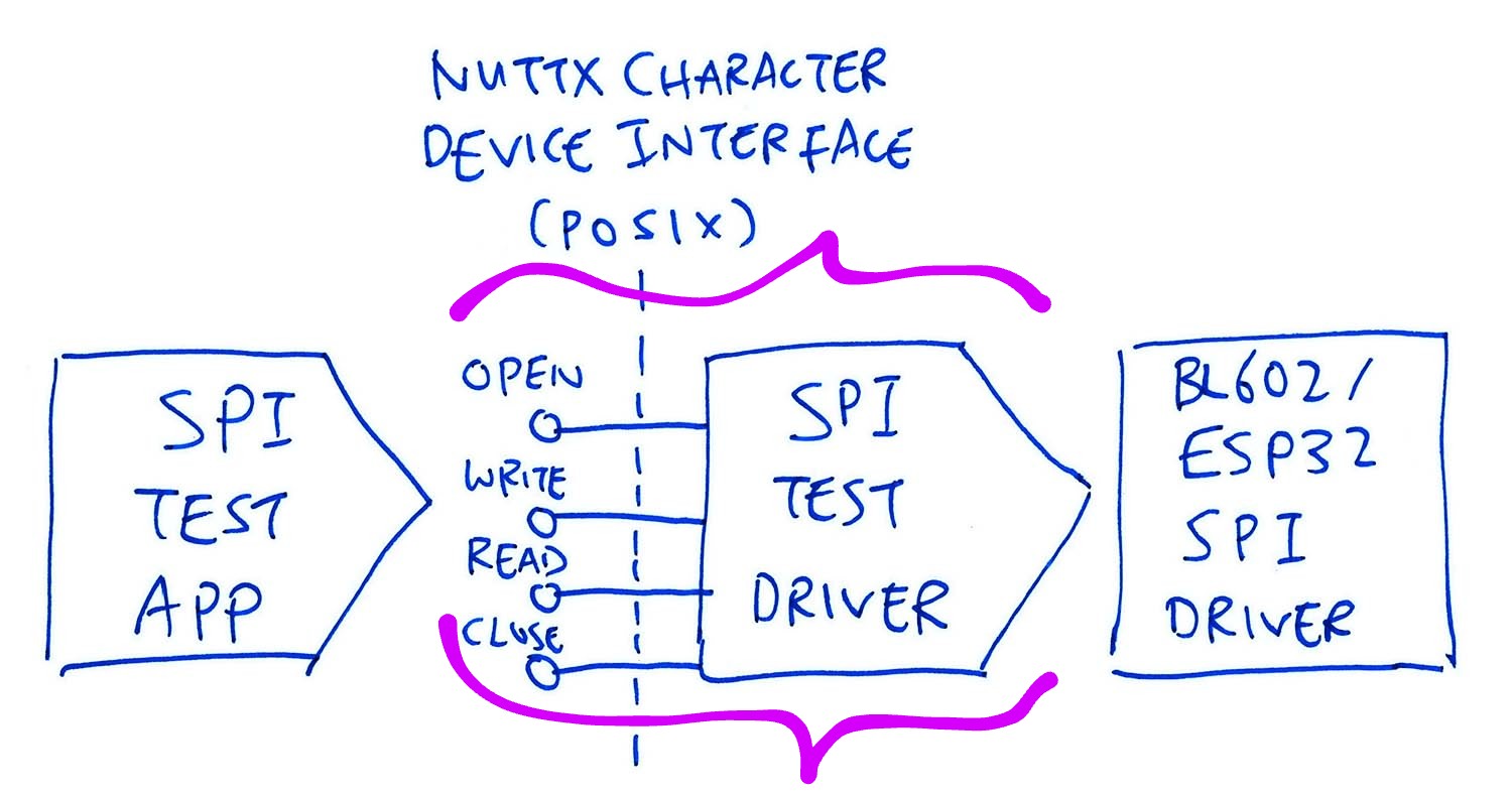
Our SPI Test Driver exposes a NuttX Character Device Interface: open(), write(), read() and close().
(Yep it looks like Linux, because NuttX is POSIX Compliant)
Our SPI Test Driver executes the SPI Operations by calling the BL602 or ESP32 SPI Driver.
(Which is equivalent to the Hardware Abstraction Layer in other operating systems)
This looks complex. Is there a simpler way?
Yes we have options for doing SPI on NuttX…
If our SPI Device is supported by an existing NuttX Device Driver, just go ahead and use the driver!
If we’re transferring data over SPI for testing only (not for a real app), we may call the SPI Transfer Interface
But today we experiment with a Custom Device Driver that will talk to our own SPI Device.
That’s why we’re building the SPI Test Driver.
(Eventually we’ll build a LoRaWAN Driver for Semtech SX1262)
Can our app call the BL602 / ESP32 SPI Driver directly?
Nope that’s not supported by NuttX. (Unlike other embedded operating systems)
It might seemingly work on BL602 and ESP32, but it will fail on platforms with Memory Protection.
(Imagine a Linux App directly calling a Kernel Driver… That’s no-no!)
Later we’ll see the layers of code that abstract the BL602 / ESP32 SPI Driver from our NuttX App.
(Thanks to Alan Carvalho de Assis for the tip!)
Must everything be done through the read() and write() interfaces?
There’s another POSIX Interface that’s supported by NuttX: ioctl().
We’ll see this when we cover the NuttX Device Driver for Semtech SX1276.
(For BL602 and ESP32)
Let’s study the code in our SPI Test Driver…
We created the SPI Test Driver by cloning another device driver, as explained here…
In the following sections we explain the SPI features that we have implemented in the driver.
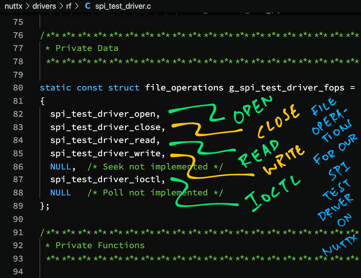
Every NuttX Character Device Driver defines a list of supported File Operations…
open(): Open the driver
close(): Close the driver
read(): Read data
write(): Write data
ioctl(): Other operations
(Plus others: seek(), poll(), …)
Our driver defines the File Operations like so: spi_test_driver.c
static const struct file_operations g_spi_test_driver_fops =
{
  spi_test_driver_open,
  spi_test_driver_close,
  spi_test_driver_read,
  spi_test_driver_write,
  NULL,  /* Seek not implemented */
  spi_test_driver_ioctl,
  NULL   /* Poll not implemented */
};

/* In spi_test_driver_register() we register the character driver */

register_driver(
  devpath,
  &g_spi_test_driver_fops,
  0666,
  priv);
spi_test_driver_register() and register_driver() are called during NuttX Startup, as explained here…
Our driver implements the write() and read() operations to transfer data over SPI.
(They will be called by our SPI Test App, as we’ll see later)
SPI is a full-duplex protocol. How will we implement read() and write()?
To simplify our SPI Test Driver, the read operation shall be buffered…
write() transmits the provided data over SPI
And saves the received data into the Receive Buffer
Then read() returns the received data from the Receive Buffer
The Receive Buffer is defined like so: spi_test_driver.c
static char recv_buffer[256];  /* Buffer for SPI response */

static int recv_buffer_len = 0;  /* Length of SPI response */
Let’s dive into the write() and read() operations.
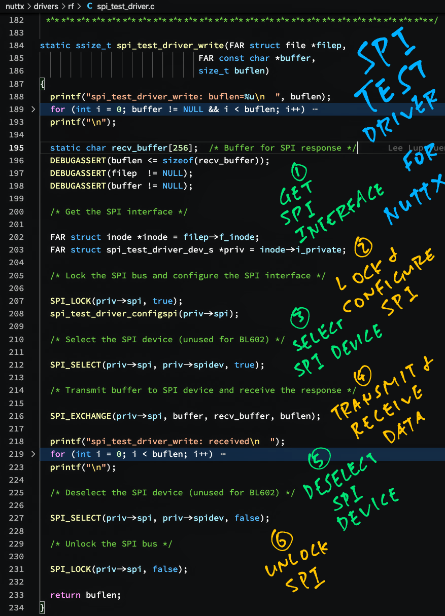
In the write() operation for our SPI Test Driver, we…
Lock the SPI Bus
Configure the SPI Interface
Select the SPI Device
Transfer SPI Data
Deselect the device and unlock the bus
Below is the implementation: spi_test_driver.c
/* Write the buffer to the SPI device */

static ssize_t spi_test_driver_write(
  FAR struct file *filep,
  FAR const char *buffer,
  size_t buflen)
{
  DEBUGASSERT(buflen <= sizeof(recv_buffer));  /* TODO: Range eheck */
  DEBUGASSERT(buffer != NULL);
  DEBUGASSERT(filep  != NULL);

  /* Get the SPI interface */

  FAR struct inode *inode = filep->f_inode;
  DEBUGASSERT(inode != NULL);
  FAR struct spi_test_driver_dev_s *priv = inode->i_private;
  DEBUGASSERT(priv != NULL);
We begin by fetching the SPI Interface from the File Struct.
Next we lock the SPI Bus and configure the SPI Interface…
  /* Lock the SPI bus and configure the SPI interface */

  DEBUGASSERT(priv->spi != NULL);
  SPI_LOCK(priv->spi, true);
  spi_test_driver_configspi(priv->spi);
(We’ll see spi_test_driver_configspi in a while)
We select the SPI Device by pulling SPI Chip Select to Low…
  /* Select the SPI device (unused for BL602) */

  SPI_SELECT(priv->spi, priv->spidev, true);
(This has no effect on BL602. The SPI Hardware automatically sets Chip Select to Low during SPI transfer)
Then we transfer the data over SPI (transmit and receive)…
  /* Transmit buffer to SPI device and receive the response */

  SPI_EXCHANGE(priv->spi, buffer, recv_buffer, buflen);
  recv_buffer_len = buflen;
Note that the received data goes into our Receive Buffer.
(Which will be returned in the read() operation)
Finally we deselect the device and unlock the bus…
  /* Deselect the SPI device (unused for BL602) */

  SPI_SELECT(priv->spi, priv->spidev, false);

  /* Unlock the SPI bus */

  SPI_LOCK(priv->spi, false);

  return buflen;
}
The return value is the number of bytes transferred.
(Deselect has no effect on BL602. The SPI Hardware automatically sets Chip Select to High after SPI transfer)
What are SPI_LOCK, SPI_SELECT and SPI_EXCHANGE?
That’s the SPI Interface for NuttX.
(More about NuttX SPI Interface)
Remember that the write() operation has saved the received SPI data into the Receive Buffer.
Thus for the read() operation we simply return the data in the Receive Buffer: spi_test_driver.c
/* Return the data received from the SPI device */

static ssize_t spi_test_driver_read(
  FAR struct file *filep,
  FAR char *buffer,
  size_t buflen)
{
  DEBUGASSERT(filep  != NULL);
  DEBUGASSERT(buffer != NULL);

  /* Copy the SPI response to the buffer */

  DEBUGASSERT(recv_buffer_len >= 0);
  DEBUGASSERT(recv_buffer_len <= buflen);  /* TODO: Range check */
  memcpy(buffer, recv_buffer, recv_buffer_len);

  /* Return the number of bytes read */

  return recv_buffer_len;
}Earlier we called spi_test_driver_configspi to configure the SPI Interface.
Below is the implementation: spi_test_driver.c
static inline void spi_test_driver_configspi(FAR struct spi_dev_s *spi)
{
  DEBUGASSERT(spi != NULL);

  /* Set SPI Mode (Polarity and Phase) and Transfer Size (8 bits) */

  SPI_SETMODE(spi, SPI_TEST_DRIVER_SPI_MODE);
  SPI_SETBITS(spi, 8);

  /* Set SPI Hardware Features and Frequency */

  SPI_HWFEATURES(spi, 0);
  SPI_SETFREQUENCY(spi, CONFIG_SPI_TEST_DRIVER_SPI_FREQUENCY);
}The code above configures the SPI Interface as follows…
SPI Mode (Polarity Phase): 0
(For BL602 we’re using Mode 1)
SPI Transfer Size: 8 bits
SPI Hardware Features: None
SPI Frequency: 1 MHz
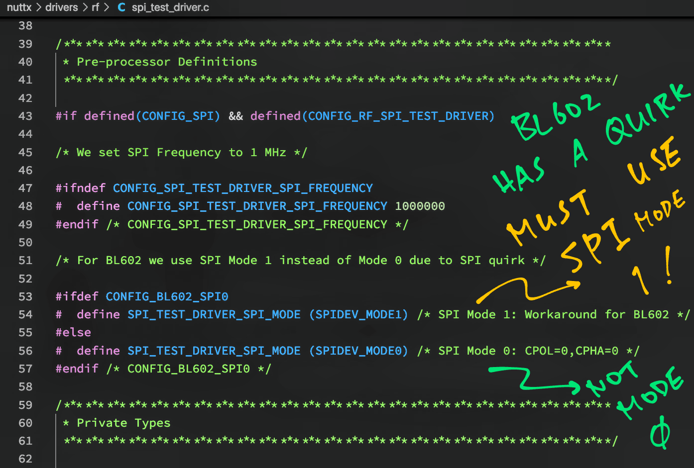
SPI Mode and SPI Frequency are defined below: spi_test_driver.c
/* We set SPI Frequency to 1 MHz */

#ifndef CONFIG_SPI_TEST_DRIVER_SPI_FREQUENCY
#define CONFIG_SPI_TEST_DRIVER_SPI_FREQUENCY 1000000
#endif /* CONFIG_SPI_TEST_DRIVER_SPI_FREQUENCY */

/* For BL602 we use SPI Mode 1 instead of Mode 0 due to SPI quirk */

#ifdef CONFIG_BL602_SPI0
#define SPI_TEST_DRIVER_SPI_MODE (SPIDEV_MODE1) /* SPI Mode 1: Workaround for BL602 */
#else
#define SPI_TEST_DRIVER_SPI_MODE (SPIDEV_MODE0) /* SPI Mode 0: CPOL=0,CPHA=0 */
#endif /* CONFIG_BL602_SPI0 */
BL602 uses SPI Mode 1 (instead of Mode 0) because of an SPI Mode Quirk in BL602.
(More about the SPI Mode Quirk)
(For BL602 and ESP32)
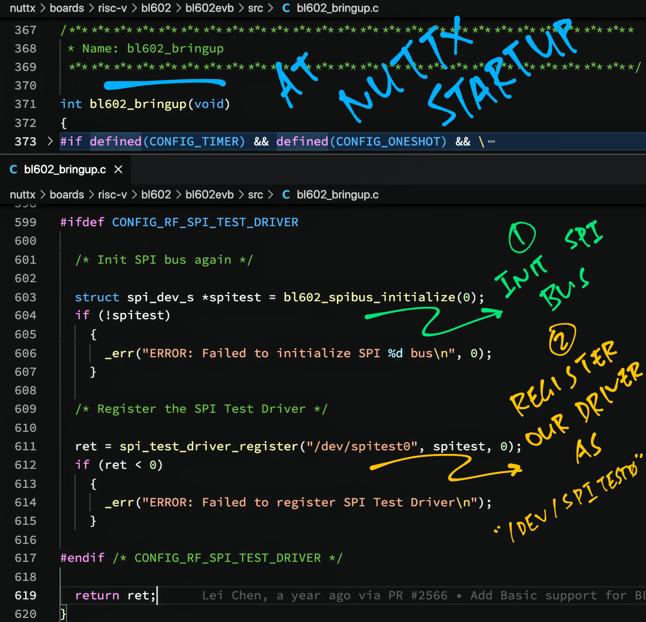
How do we load our SPI Test Driver at startup?
During NuttX Startup, we load our SPI Test Driver like so: bl602_bringup.c
int bl602_bringup(void)
{
  ...
#ifdef CONFIG_RF_SPI_TEST_DRIVER

  /* Init SPI bus again */

  struct spi_dev_s *spitest = bl602_spibus_initialize(0);
  if (!spitest)
    {
      _err("ERROR: Failed to initialize SPI %d bus\n", 0);
    }

  /* Register the SPI Test Driver */

  ret = spi_test_driver_register("/dev/spitest0", spitest, 0);
  if (ret < 0)
    {
      _err("ERROR: Failed to register SPI Test Driver\n");
    }

#endif /* CONFIG_RF_SPI_TEST_DRIVER */
bl602_bringup is the NuttX Startup Function for BL602.
(esp32_bringup for ESP32)
We modified the Startup Function to register our SPI Test Driver, which loads the driver into NuttX at startup.
Let’s run NuttX on BL602 / ESP32 and check that our SPI Test Driver loads correctly…
Install the build prerequisites…
Download the modified source code…
mkdir nuttx
cd nuttx
git clone --branch spi_test https://github.com/lupyuen/nuttx nuttx
git clone --branch spi_test https://github.com/lupyuen/nuttx-apps apps(For PineDio Stack BL604: The SPI Test Driver is already preinstalled)
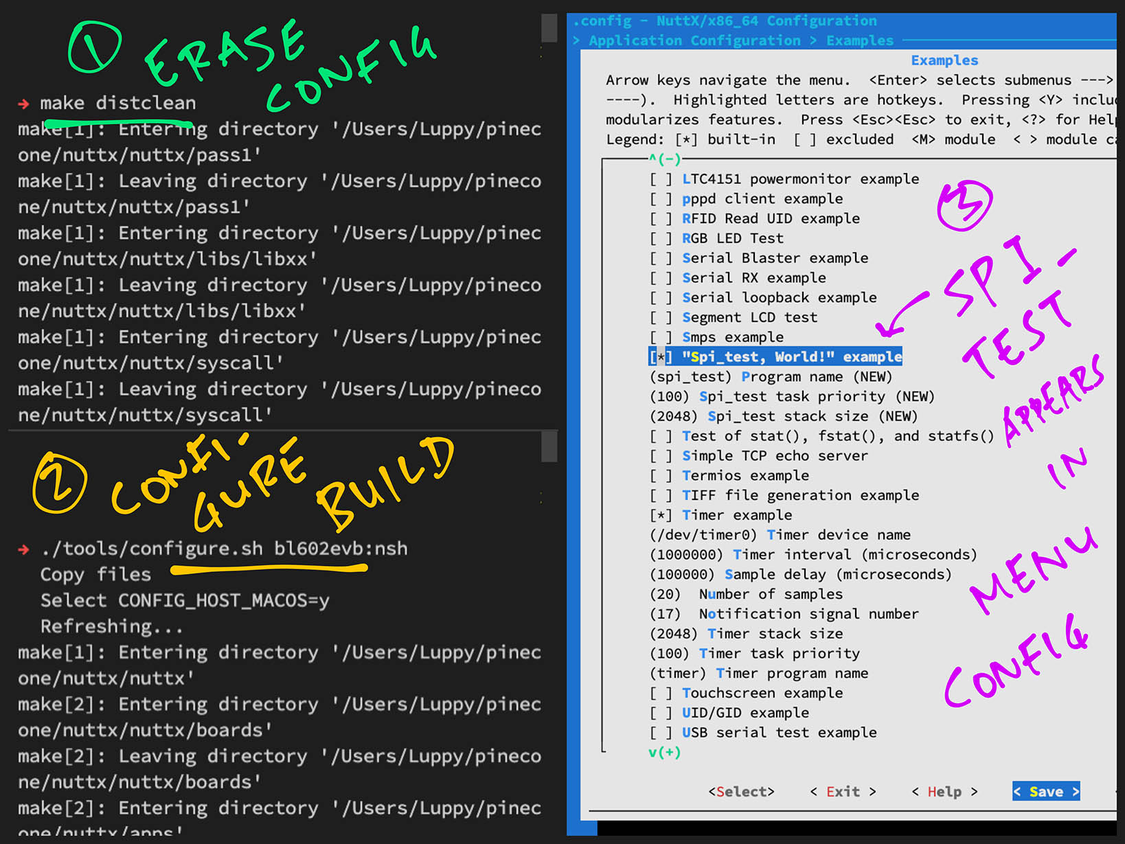
Configure the build…
cd nuttx
## For BL602: Configure the build for BL602
./tools/configure.sh bl602evb:nsh
## For PineDio Stack BL604: Configure the build for BL604
./tools/configure.sh bl602evb:pinedio
## For ESP32: Configure the build for ESP32.
## TODO: Change "esp32-devkitc" to our ESP32 board.
./tools/configure.sh esp32-devkitc:nsh
## Edit the Build Config
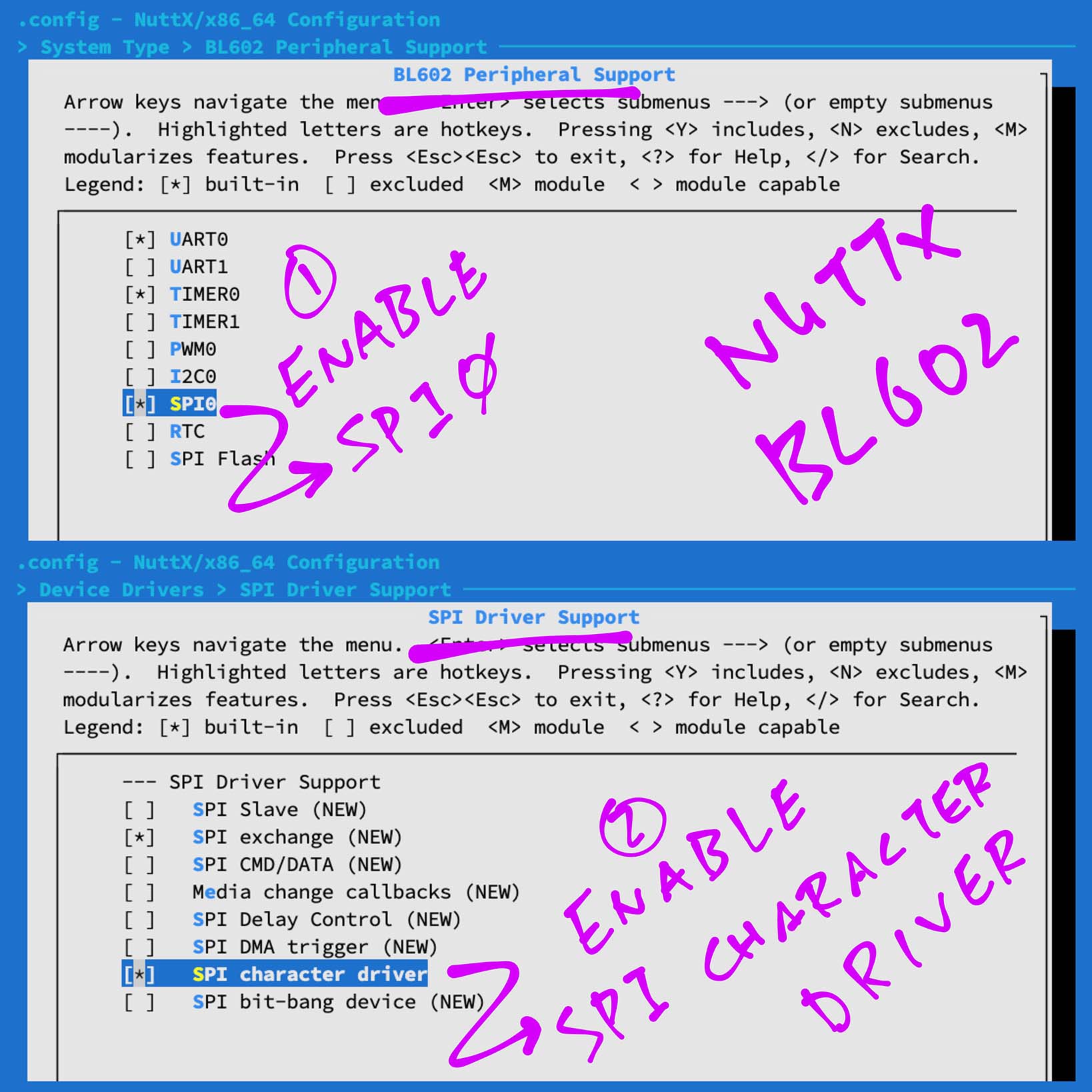
make menuconfig Enable the SPI Peripheral and SPI Character Driver in menuconfig…
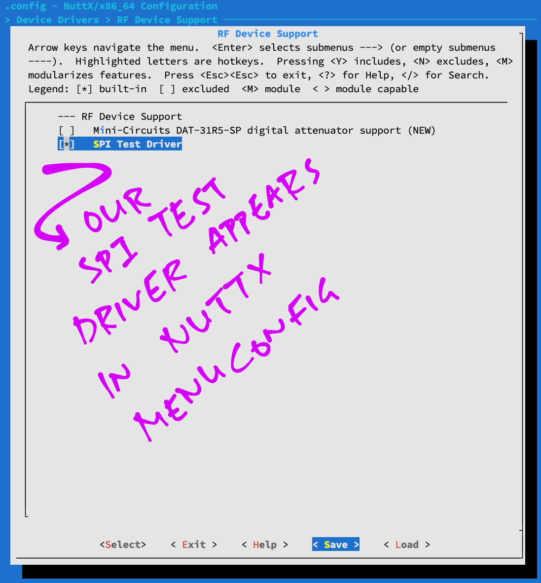
Enable our SPI Test Driver…
Enable SPI logging for easier troubleshooting…
Save the configuration and exit menuconfig
For ESP32: Edit esp32_bringup.c to register our SPI Test Driver (See this)
Build, flash and run the NuttX Firmware on BL602 or ESP32…
In the NuttX Shell, enter…
ls /devOur SPI Test Driver appears as “/dev/spitest0”
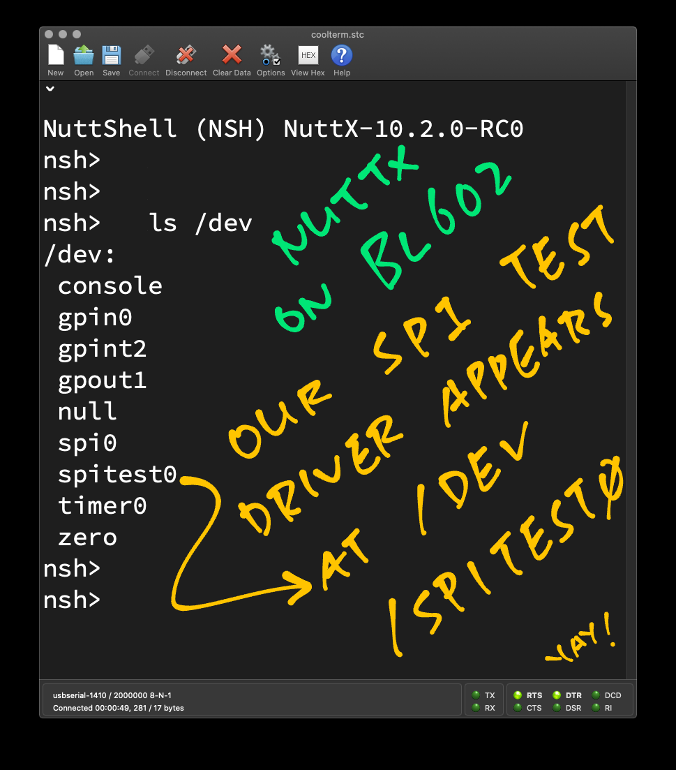
Congratulations NuttX has loaded our Device Driver!
Let’s talk about our SPI Test App.
(For BL602 and ESP32)
We’ve seen the write() and read() operations in our SPI Test Driver. Now we learn how they are called by our SPI Test App…
We created the SPI Test App by cloning another app, as explained here…
We’ll do the following in our SPI Test App…
Open our SPI Test Driver
Transmit data over SPI
Receive data over SPI
Close our SPI Test Driver
Earlier we saw that our SPI Test Driver appears in NuttX as “/dev/spitest0”
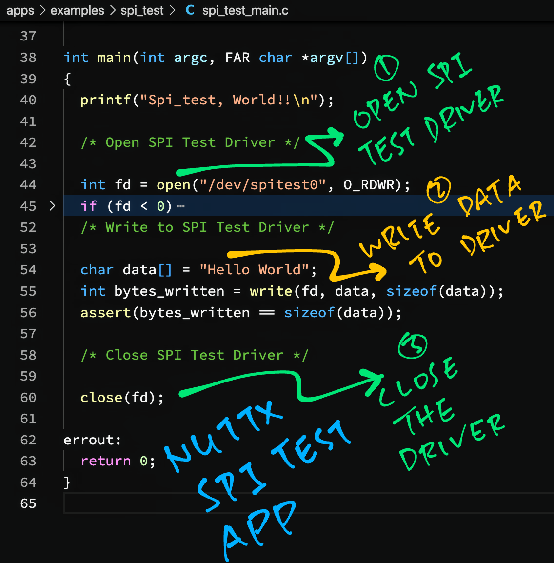
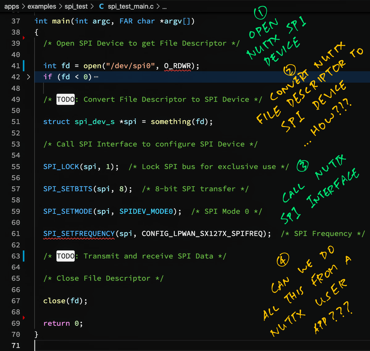
Let’s open the driver: spi_test_main.c
int main(int argc, FAR char *argv[])
{
  /* Open SPI Test Driver */

  int fd = open("/dev/spitest0", O_RDWR);
  assert(fd >= 0);  /* TODO: Handle error */
(Yep this looks very Linux-like!)
open() returns a File Descriptor that we’ll use to transmit and receive data over SPI.
Our SPI Test Driver implements a write() operation that will transmit SPI data.
We call it like so…
  /* Write to SPI Test Driver */

  static char data[] = "Hello World";
  int bytes_written = write(fd, data, sizeof(data));
  assert(bytes_written == sizeof(data));
This transmits the string “Hello World” to our SPI Device.
(Including the terminating null character)
Remember that the write() operation will actually transmit and receive SPI data at the same time.
We read the received SPI data by calling read()…
  /* Read response from SPI Test Driver */

  static char rx_data[256];  /* Buffer for SPI response */
  int bytes_read = read(fd, rx_data, sizeof(rx_data));
assert(bytes_read == sizeof(get_status));This code isn’t in our SPI Test App, we’ll see this later when we test with Semtech SX1262.
Finally we close the File Descriptor for our SPI Test Driver…
  /* Close SPI Test Driver */

  close(fd);
  return 0;
}
Let’s run our SPI Test App!
(For BL602 and ESP32)
Follow these steps to run our SPI Test App on BL602 or ESP32…
Assume that we have downloaded and configured our NuttX code…
Edit the build configuration…
make menuconfigEnable our SPI Test App in menuconfig…
Save the configuration and exit menuconfig
Build, flash and run the NuttX Firmware on BL602 or ESP32…
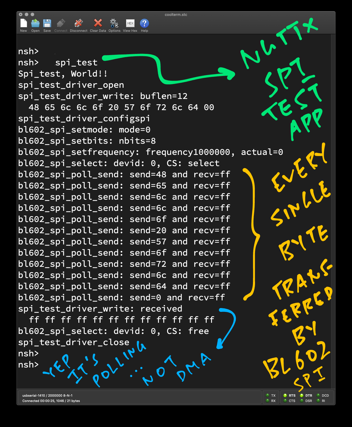
In the NuttX Shell, enter…
spi_testWe should see every byte transmitted and received over SPI.
(Thanks to SPI Logging!)
The pic below shows that our app has transmitted the string “Hello World” (plus the terminating null) over SPI.
But because we’re not connected to any SPI Device, we don’t receive any meaningful response. (It’s all 0xFF)
(For BL602 and ESP32)
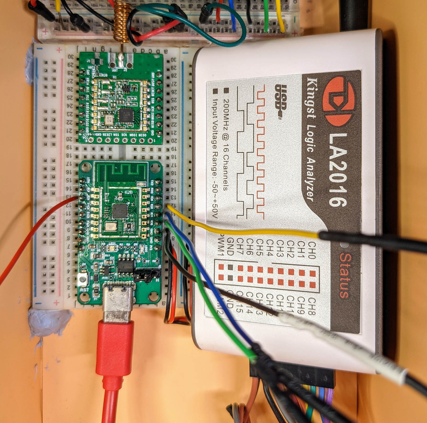
How do we check if our app is transmitting SPI data correctly?
Let’s connect a Logic Analyser to BL602 / ESP32 and verify the SPI output…
| Logic Analyser | BL602 Pin | ESP32 Pin |
|---|---|---|
| MOSI | GPIO 1 | GPIO 13 |
| MISO | GPIO 0 | GPIO 12 |
| SCK | GPIO 3 | GPIO 14 |
| CS | GPIO 2 | GPIO 15 |
| GND | GND | GND |
How did we get the GPIO Pin Numbers for the SPI Port?
For BL602: SPI Pins are defined in board.h
#define BOARD_SPI_CS   (GPIO_INPUT | GPIO_PULLUP | GPIO_FUNC_SPI | GPIO_PIN2)
#define BOARD_SPI_MOSI (GPIO_INPUT | GPIO_PULLUP | GPIO_FUNC_SPI | GPIO_PIN1)
#define BOARD_SPI_MISO (GPIO_INPUT | GPIO_PULLUP | GPIO_FUNC_SPI | GPIO_PIN0)
#define BOARD_SPI_CLK  (GPIO_INPUT | GPIO_PULLUP | GPIO_FUNC_SPI | GPIO_PIN3)
(Which pins can be used? See this)
For ESP32: SPI Pins are defined in Kconfig
config ESP32_SPI2_CSPIN
	int "SPI2 CS Pin"
	default 15
	range 0 39

config ESP32_SPI2_CLKPIN
	int "SPI2 CLK Pin"
	default 14
	range 0 39

config ESP32_SPI2_MOSIPIN
	int "SPI2 MOSI Pin"
	default 13
	range 0 39

config ESP32_SPI2_MISOPIN
	int "SPI2 MISO Pin"
	default 12
	range 0 39
When we run “spi_test”, we see this in our Logic Analyser…
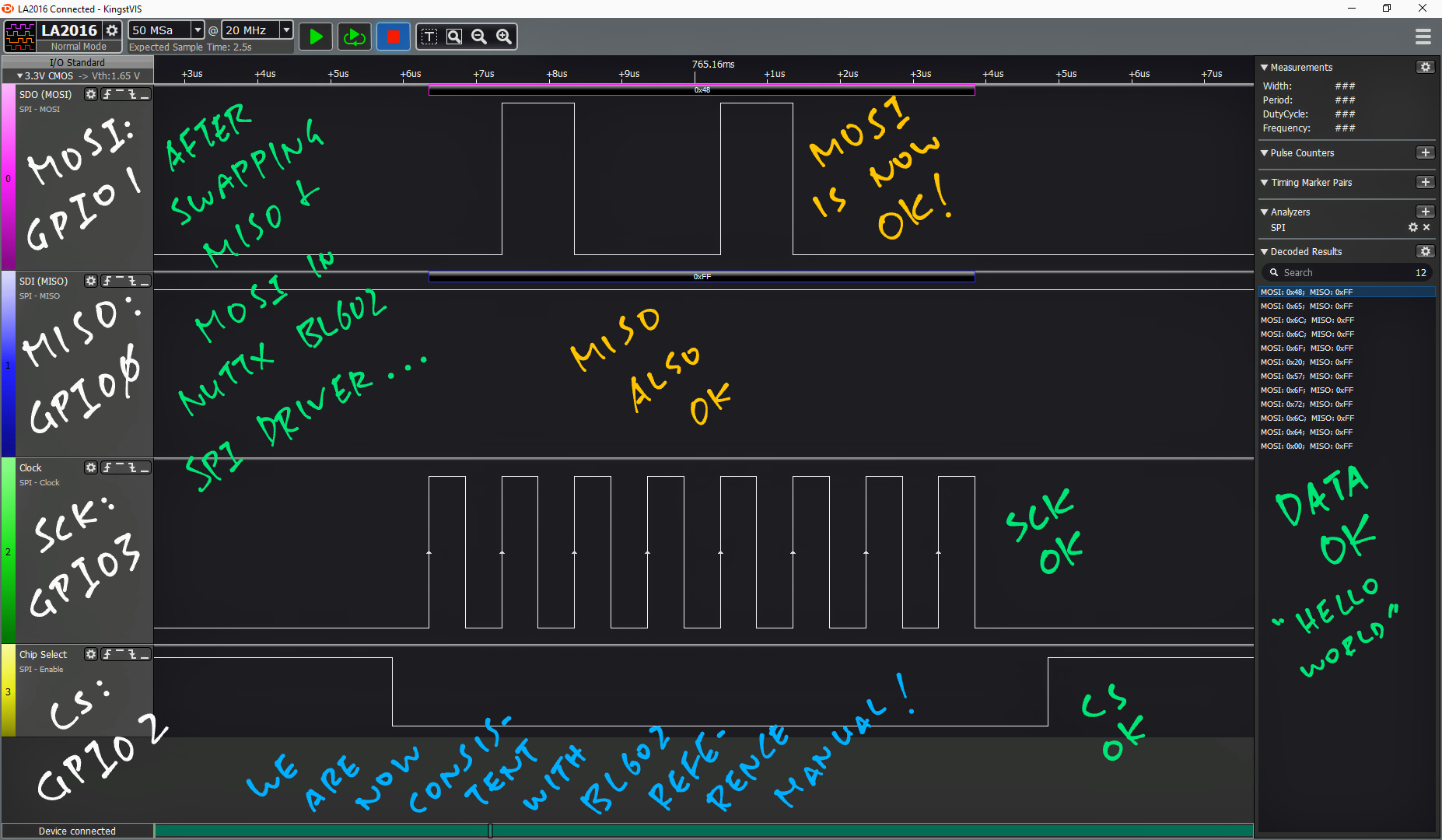
This looks OK! Though MISO is idle because it’s not connected to an SPI Device.
Let’s test with a real SPI Device: Semtech SX1262.
(BL602 has a quirk that swaps MISO and MOSI, the fix is explained here)
(For BL602 and ESP32)
If we zoom out the above display in the Logic Analyser, we see a problem with SPI Chip Select on BL602…
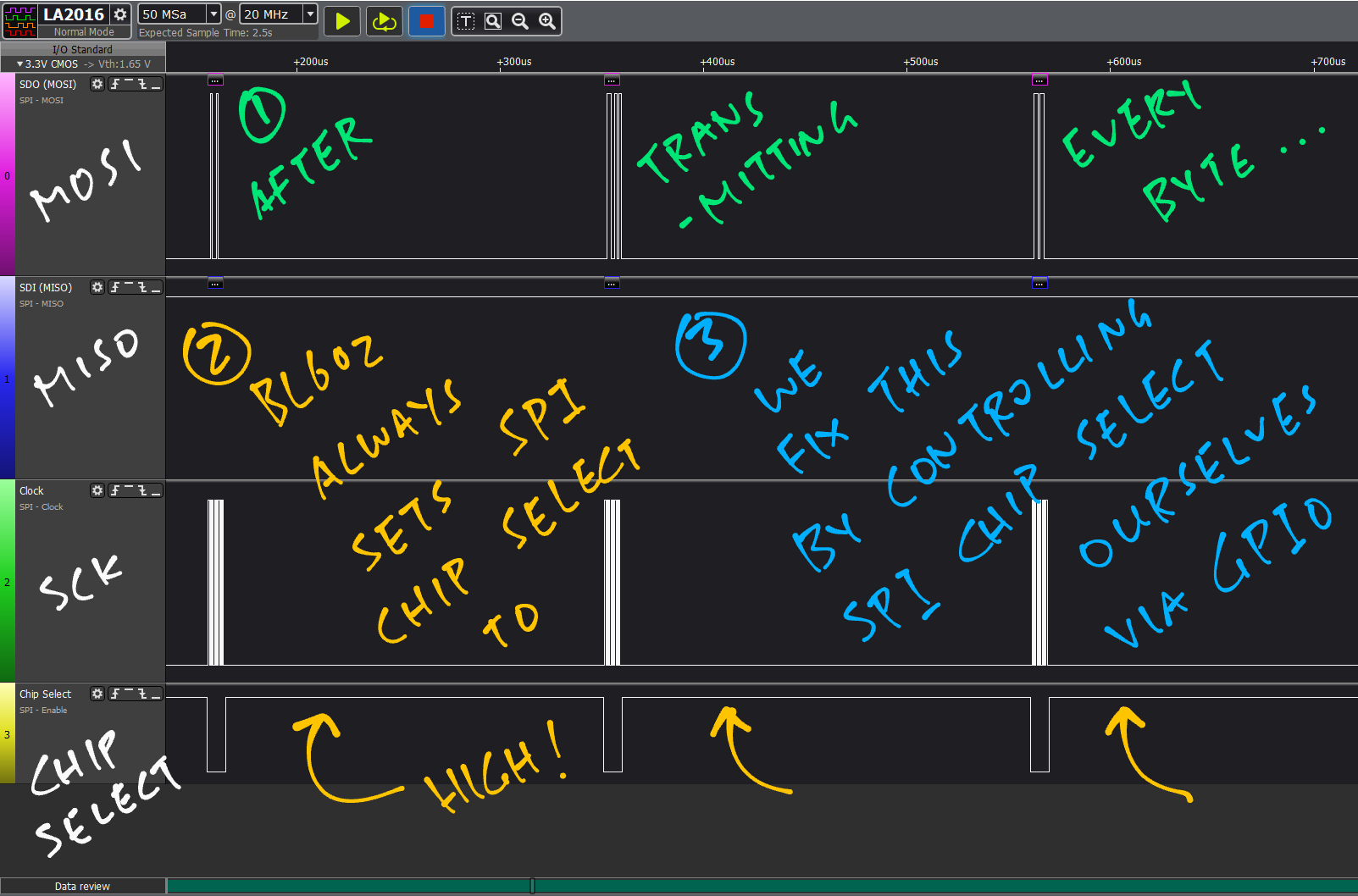
BL602 sets Chip Select to High after EVERY byte!
This will be a problem for Semtech SX1262 (LoRa Transceiver)…
It expects Chip Select to be High after the entire multi-byte command has been transmitted! (Not after every byte)
(ESP32 doesn’t have this problem, according to @4ever_freedom)
Can we control SPI Chip Select ourselves?
Yes, we may control Chip Select ourselves with the GPIO Output function in NuttX.
This means we designate a GPIO Output Pin that will be used for Chip Select.
And we call NuttX to flip the pin Low and High, before and after each SPI transfer.
Is there another reason for controlling Chip Select with GPIO?
On many BL602 / ESP32 boards, the SPI Bus (MISO, MOSI and SCK) is shared by multiple SPI Devices.
But each SPI Device has its own Chip Select Pin.
For such boards we’ll have to control each Chip Select Pin with GPIO.
(PineDio Stack BL604 shares its SPI Bus with SX1262 Transceiver, ST7789 Display and SPI Flash)
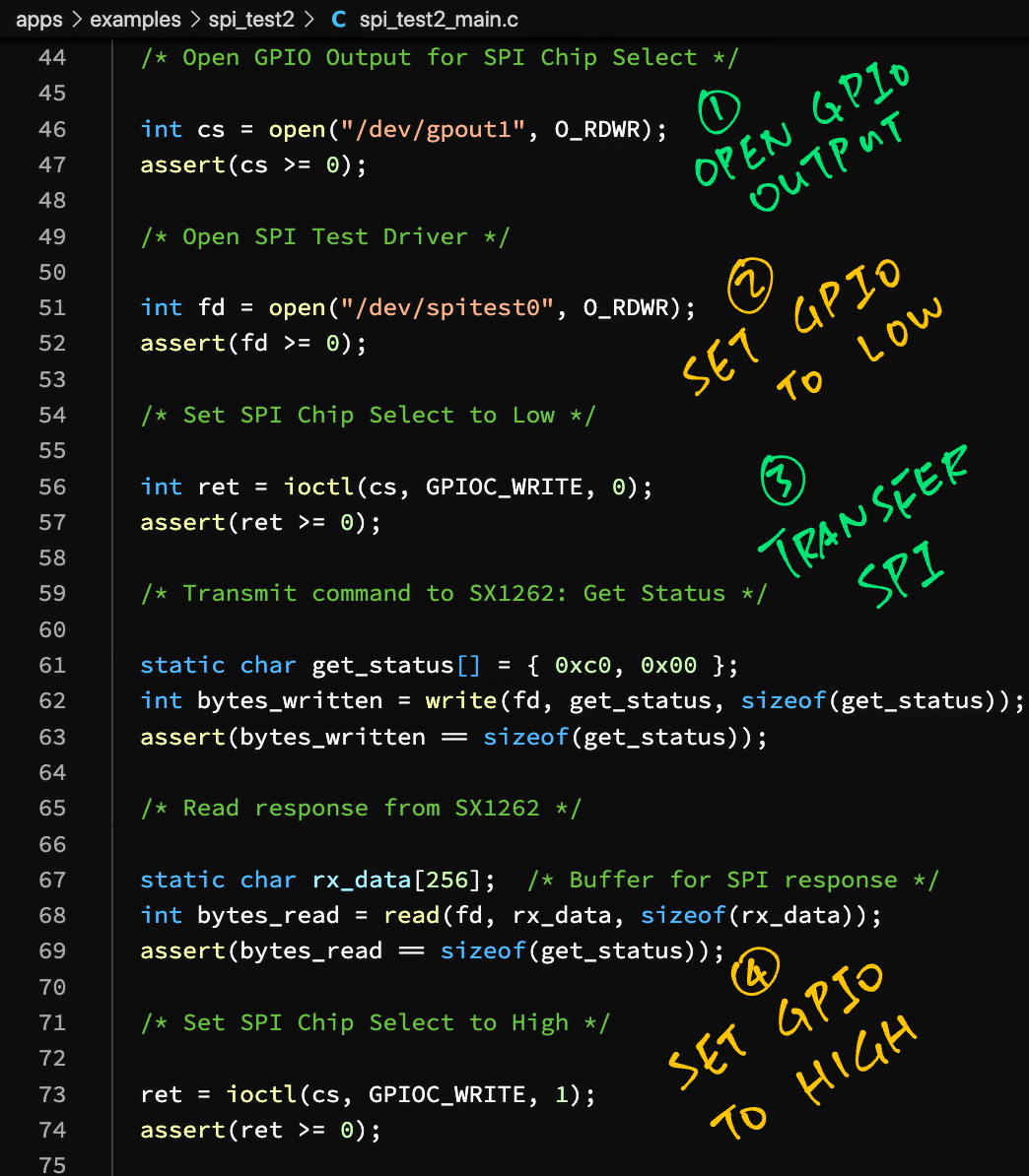
Let’s look at the code in SPI Test App #2 that controls Chip Select with GPIO: spi_test2_main.c
/* Open GPIO Output for SPI Chip Select */

int cs = open("/dev/gpout1", O_RDWR);
assert(cs >= 0);  /* TODO: Handle error */
(Renamed to /dev/gpio1 as of Dec 2021)
This is new: We open the GPIO Output device “/dev/gpout1” for the SPI Chip Select Pin.
Next we open our SPI Test Driver as before…
/* Open SPI Test Driver */

int fd = open("/dev/spitest0", O_RDWR);
assert(fd >= 0);
Then we set our GPIO Output / Chip Select to Low by calling ioctl()…
/* Set SPI Chip Select to Low */

int ret = ioctl(cs, GPIOC_WRITE, 0);
assert(ret >= 0);
Now that the SPI Device is active, we can transmit and receive our SPI data…
/* Transmit command to SX1262: Get Status */

static char get_status[] = { 0xc0, 0x00 };
int bytes_written = write(fd, get_status, sizeof(get_status));
assert(bytes_written == sizeof(get_status));

/* Read response from SX1262 */

static char rx_data[256];  /* Buffer for SPI response */
int bytes_read = read(fd, rx_data, sizeof(rx_data));
assert(bytes_read == sizeof(get_status));
(We’ll explain get_status in the next section)
Finally we set our GPIO Output / Chip Select to High…
/* Set SPI Chip Select to High */

ret = ioctl(cs, GPIOC_WRITE, 1);
assert(ret >= 0);

/* Close SPI Test Driver and GPIO Output */

close(fd);
close(cs);
And close the SPI Test Driver and GPIO Output.
Let’s watch SPI Test App #2 in action with Semtech SX1262.
(For BL602 and ESP32)
Semtech SX1262 is a LoRa Transceiver (Radio Transmitter + Receiver) that’s not yet supported by NuttX.
(Though the older model SX1276 is supported by NuttX)
Today we shall send two short commands to SX1262 for testing…
Get Status: We transmit this sequence of bytes to SX1262…
C0 00We expect the SPI Response to look like this…
A2 22(The response might get muddled, we’ll learn why in a while)
Read Register 0x08: We transmit this sequence of bytes to SX1262…
1D 00 08 00 00We expect the SPI Response to end with 0x80 like this…
A2 A2 A2 A2 80We send the “Get Status” command with this code: spi_test2_main.c
/* Transmit command to SX1262: Get Status */

static char get_status[] = { 0xc0, 0x00 };
int bytes_written = write(fd, get_status, sizeof(get_status));
assert(bytes_written == sizeof(get_status));

/* Read response from SX1262 */

static char rx_data[256];  /* Buffer for SPI response */
int bytes_read = read(fd, rx_data, sizeof(rx_data));
assert(bytes_read == sizeof(get_status));

/* Show the received status */

printf("\nSX1262 Status is %d\n", (rx_data[1] >> 4) & 0b111);  /* Bits 6:4 */
And the “Read Register 0x08” command with this code: spi_test2_main.c
/* Transmit command to SX1262: Read Register 8 */

static char read_reg[] = { 0x1d, 0x00, 0x08, 0x00, 0x00 };
bytes_written = write(fd, read_reg, sizeof(read_reg));
assert(bytes_written == sizeof(read_reg));

/* Read response from SX1262 */

bytes_read = read(fd, rx_data, sizeof(rx_data));
assert(bytes_read == sizeof(read_reg));

/* Show the received register value */

printf("\nSX1262 Register 8 is 0x%02x\n", rx_data[4]);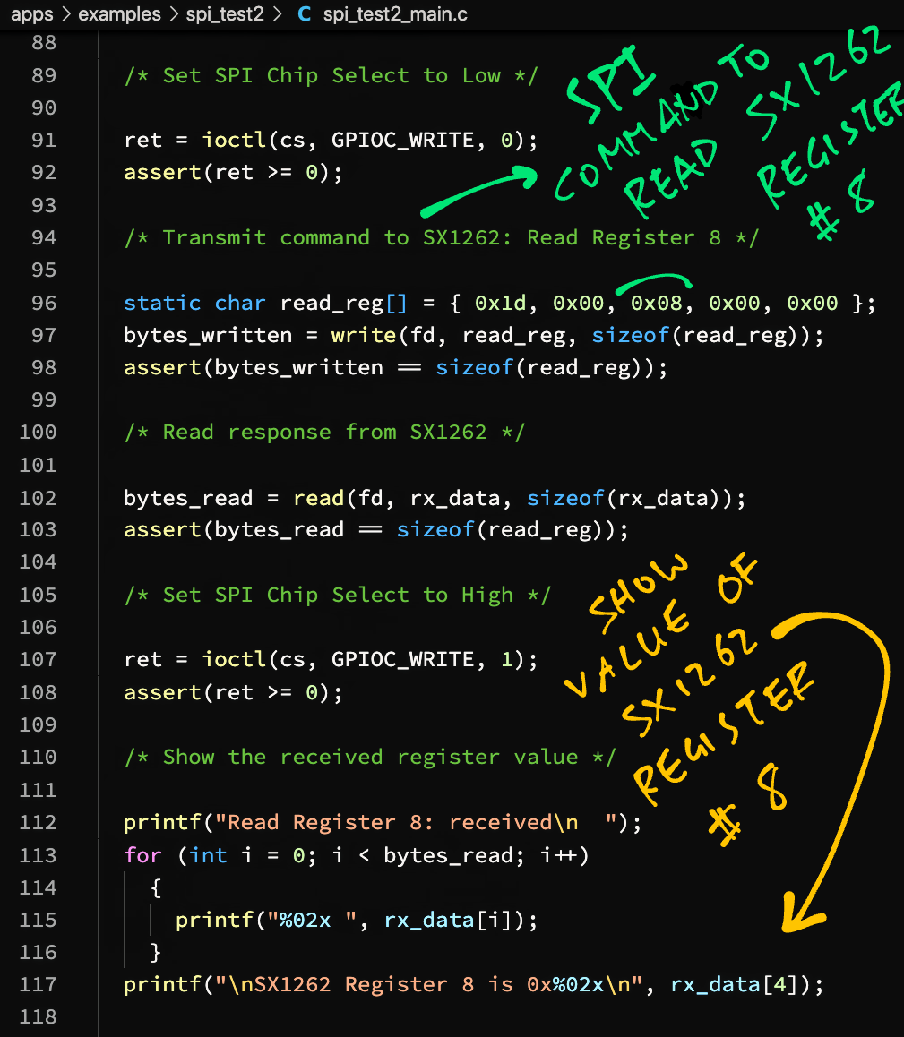
We connect SX1262 to BL602 / ESP32 as follows…
| SX1262 | BL602 Pin | ESP32 Pin | Colour |
|---|---|---|---|
| MOSI | GPIO 1 | GPIO 13 | Yellow |
| MISO | GPIO 0 | GPIO 12 | Light Green |
| SCK | GPIO 3 | GPIO 14 | Blue |
| CS | GPIO 11 | GPIO 15 / 16 | Dark Green |
| BUSY | GPIO 14 | GPIO 18 / 17 | |
| DIO1 | GPIO 17 | GPIO 22 | |
| VCC | 3V3 | 3V3 | Red |
| GND | GND | GND | Black |
Here’s SX1262 connected to PineCone BL602…
(Busy and DIO1 Pins are not connected, we’ll need them for LoRa in the next artice)
Why did we connect Chip Select to GPIO 11 / 15 / 16?
Remember that we’re controlling SPI Chip Select ourselves through GPIO Output, which is defined as follows…
For BL602: GPIO Output Pin is defined as GPIO 11 in board.h
#define BOARD_GPIO_OUT1 \
  (GPIO_OUTPUT | GPIO_FLOAT | \
GPIO_FUNC_SWGPIO | GPIO_PIN11)For ESP32: GPIO Output Pin depends on our ESP32 Board (and may be customised)…
ESP32-DevKitC defines GPIO 15 as the default GPIO Output Pin: esp32_gpio.c
/* Output pins. GPIO15 is used as an example, any other outputs could be used. */
#define GPIO_OUT1    15

/* Input pins. GPIO18 is used as an example, any other inputs could be
 * used.
 */
#define GPIO_IN1     18

/* Interrupt pins.  GPIO22 is used as an example, any other inputs could be
 * used.
 */
#define GPIO_IRQPIN1  22
ESP32-WROVER-KIT uses GPIO 16 for GPIO Output: esp32_gpio.c
#define GPIO_OUT1    16
#define GPIO_IN1     17
#define GPIO_IRQPIN1 22
TTGO-LoRa-ESP32 uses GPIO 15 for GPIO Output: esp32_gpio.c
#define GPIO_OUT1    15
#define GPIO_IN1     18
#define GPIO_IRQPIN1 22Follow these steps to run our SPI Test App #2 on BL602 or ESP32…
Assume that we have downloaded and configured our NuttX code…
Edit the build configuration…
make menuconfigEnable the GPIO Driver…
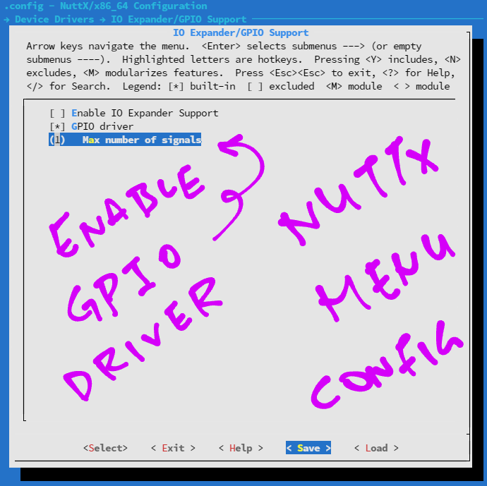
Hit “Exit” until the Top Menu appears
(“NuttX/x64_64 Configuration”)
Enable SPI Test App #2…
Select “Application Configuration” → “Examples”
Check the box for “spi_test2”
Save the configuration and exit menuconfig
Build, flash and run the NuttX Firmware on BL602 or ESP32…
In the NuttX Shell, enter…
spi_test2(Pic below)
We should see the output from the “Get Status” command…
Get Status: received
  8a 8a
SX1262 Status is 0
(This output is not quite correct, we’ll explain why in the next section)
And the output from the “Read Register 0x08” command…
Read Register 8: received
  a8 a8 a8 a8 80
SX1262 Register 8 is 0x80
The value of Register 0x08 is correct: 0x80
Yep our NuttX App is working OK with SX1262!
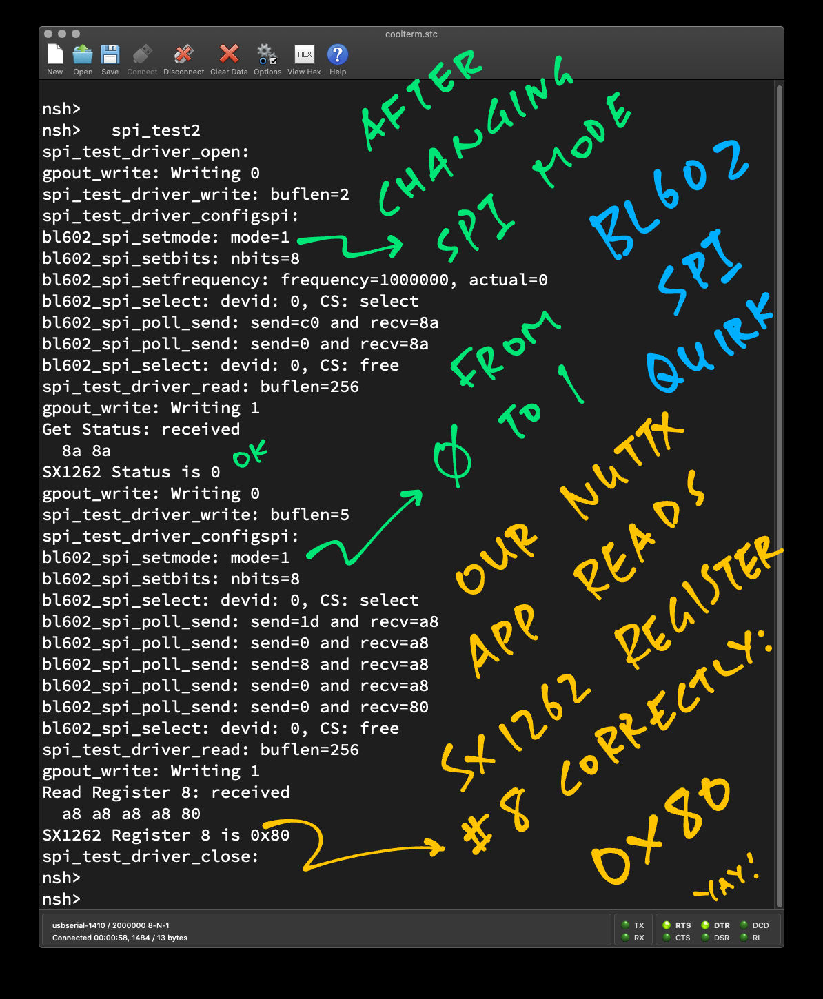
(BL602 has a quirk: We must use SPI Mode 1 instead of Mode 0 or the register value will be garbled)
Let’s run SPI Test App #2 on a new gagdet with onboard SX1262: PineDio Stack BL604.
(For BL604 only)
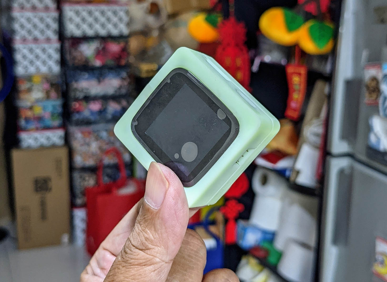
Pine64 has just sent me a prototype of PineDio Stack BL604 (version 2, pic above) with onboard SX1262 LoRa Transceiver, ST7789 Display, SPI Flash, GPS, Compass, Touch Panel, Heart Rate Sensor, Vibrator, …
(Yep multiple devices on the same SPI Bus)
Let’s test NuttX with PineDio Stack BL604 and its onboard SX1262! Here are the innards…
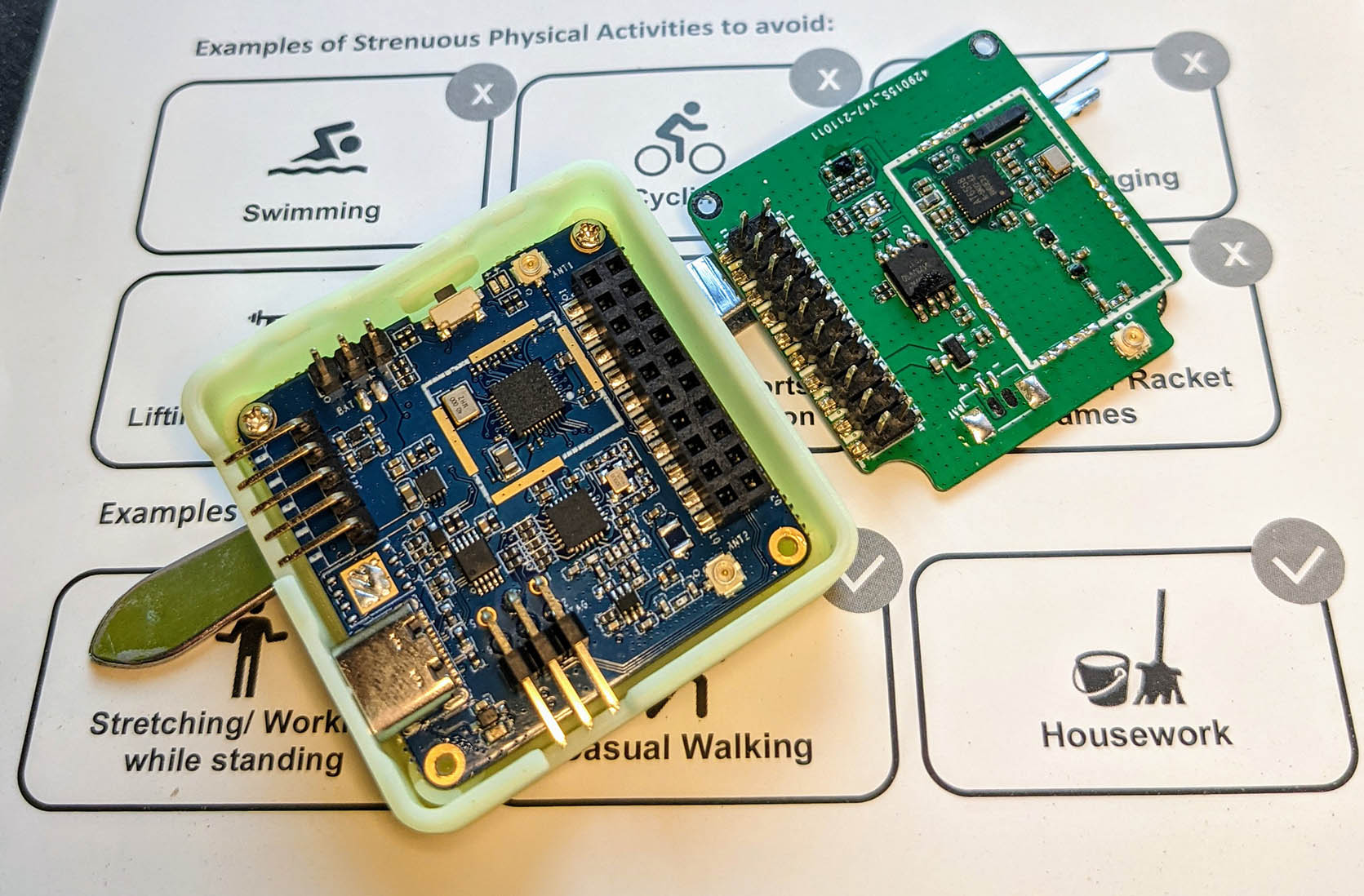
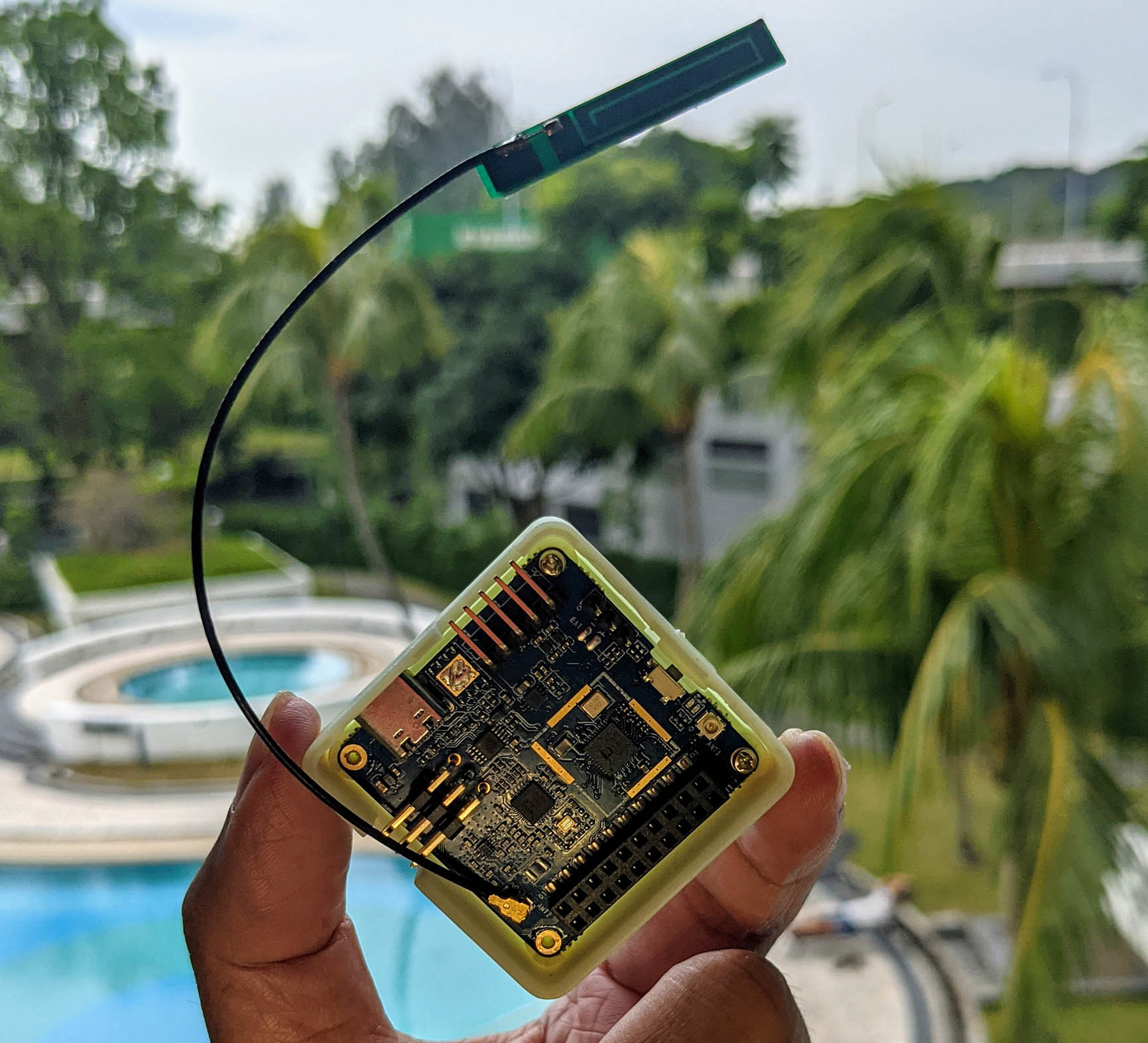
Before testing, remember to connect the LoRa Antenna…
(So we don’t fry the SX1262 Transceiver as we charge up the Power Amplifier)
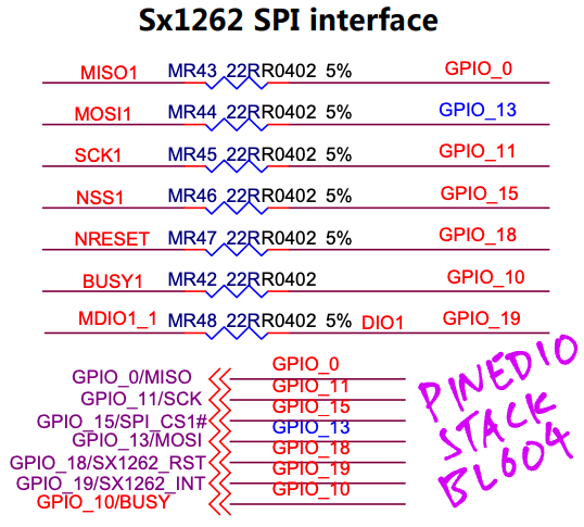
Based on this schematic for PineDio Stack BL604 (version 2)…
We update the following BL604 Pin Definitions in board.h
| SX1262 | BL604 Pin | NuttX Pin |
|---|---|---|
| MOSI | GPIO 13 | BOARD_SPI_MOSI |
| MISO | GPIO 0 | BOARD_SPI_MISO |
| SCK | GPIO 11 | BOARD_SPI_CLK |
| CS | GPIO 15 | BOARD_GPIO_OUT1 |
| BUSY | GPIO 10 | BOARD_GPIO_IN1 |
| DIO1 | GPIO 19 | BOARD_GPIO_INT1 |
| NRESET | GPIO 18 | Not assigned yet |
/* Busy Pin for PineDio SX1262 */

#define BOARD_GPIO_IN1    (GPIO_INPUT | GPIO_FLOAT | \
                            GPIO_FUNC_SWGPIO | GPIO_PIN10)

/* SPI Chip Select for PineDio SX1262 */

#define BOARD_GPIO_OUT1   (GPIO_OUTPUT | GPIO_PULLUP | \
                            GPIO_FUNC_SWGPIO | GPIO_PIN15)

/* GPIO Interrupt (DIO1) for PineDio SX1262 */

#define BOARD_GPIO_INT1   (GPIO_INPUT | GPIO_PULLUP | \
                            GPIO_FUNC_SWGPIO | GPIO_PIN19)

/* SPI Configuration: Chip Select is unused because we control via GPIO instead */

#define BOARD_SPI_CS   (GPIO_INPUT | GPIO_PULLUP | GPIO_FUNC_SPI | GPIO_PIN8)  /* Unused */
#define BOARD_SPI_MOSI (GPIO_INPUT | GPIO_PULLUP | GPIO_FUNC_SPI | GPIO_PIN13)
#define BOARD_SPI_MISO (GPIO_INPUT | GPIO_PULLUP | GPIO_FUNC_SPI | GPIO_PIN0)
#define BOARD_SPI_CLK  (GPIO_INPUT | GPIO_PULLUP | GPIO_FUNC_SPI | GPIO_PIN11)
(Which pins can be used? See this)
(Remember that GPIO Output BOARD_GPIO_OUT1 becomes our Chip Select)
Today we won’t use BOARD_GPIO_IN1 (Busy Pin) and BOARD_GPIO_INT1 (DIO1).
But eventually we’ll use them when we port the LoRaWAN Stack to PineDio Stack BL604!
Our final task for today: Run SPI Test App #2 on PineDio Stack BL604 (with onboard SX1262)…
Assume that we have downloaded and configured our NuttX code…
Edit the Pin Definitions as shown above…
Build, flash and run the NuttX Firmware…
In the NuttX Shell, enter…
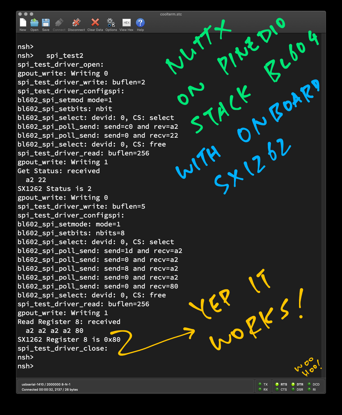
spi_test2(Pic below)
We should see the output from the “Get Status” command…
Get Status: received
  a2 22
SX1262 Status is 2
(This looks different from the BL602 output, we’ll explain why in a while)
And the output from the “Read Register 0x08” command…
Read Register 8: received
  a2 a2 a2 a2 80
SX1262 Register 8 is 0x80
The value of Register 0x08 is correct: 0x80
Our SPI Test App #2 runs OK on PineDio Stack BL604 with onboard SX1262! 🎉
(The results are consistent with SX1262 tested on Linux with SPI Mode 0)
Why did the “Get Status” command return different results on BL602 vs BL604?
On PineCone BL602 we configure GPIO Output (Chip Select) like this…
#define BOARD_GPIO_OUT1 \
  (GPIO_OUTPUT | GPIO_FLOAT | \
GPIO_FUNC_SWGPIO | GPIO_PIN11)On PineDio Stack BL604 we do this…
#define BOARD_GPIO_OUT1 \
  (GPIO_OUTPUT | GPIO_PULLUP | \
GPIO_FUNC_SWGPIO | GPIO_PIN15)See the difference? PineCone BL602 configures the GPIO Output (Chip Select) as GPIO_FLOAT, whereas BL604 configures it as GPIO_PULLUP.
With GPIO_FLOAT, Chip Select defaults to the Low State at startup.
Which activates SX1262 on the SPI Bus at startup, possibly interpreting spurious commands and causing the “Get Status” command to fail.
PineDio Stack BL604 does it correctly: It sets Chip Select to the High State at startup (GPIO_PULLUP). Which deactivates SX1262 on the SPI Bus at startup.
Anything else we missed?
On PineDio Stack BL604 the SPI Bus is shared by multiple SPI Devices: SX1262 Transceiver, ST7789 Display, SPI Flash.
We ought to flip the Chip Select for other SPI Devices to High, to deactivate the other devices and prevent crosstalk on the SPI Bus.
Now that we have NuttX talking OK to the SX1262 LoRa Transceiver… We’re ready to port LoRa and LoRaWAN to NuttX!
Over the next couple of articles we shall migrate the LoRa + LoRaWAN code incrementally to NuttX…
NuttX works great with the ST7789 SPI Display and LVGL Graphics Libary, right out of the box…
We’ll also explore I2C on NuttX, which is super useful for IoT sensors…
I’m super excited about porting the Rust Embedded HAL to NuttX. Here’s how we integrated NuttX GPIO, SPI and I2C with Rust…
Many Thanks to my GitHub Sponsors for supporting my work! This article wouldn’t have been possible without your support.
Got a question, comment or suggestion? Create an Issue or submit a Pull Request here…
This article is the expanded version of this Twitter Thread
We have already ported LoRaWAN to BL602 IoT SDK (see this), why are we porting again to NuttX?
Regrettably BL602 IoT SDK has been revamped (without warning) to the new “hosal” HAL (see this), and the LoRaWAN Stack will no longer work on the revamped BL602 IoT SDK.
For easier maintenance, we shall code our BL602 and BL604 projects with Apache NuttX OS instead.
(Which won’t get revamped overnight!)
SPI on BL602 NuttX now supports Direct Memory Access (DMA) for speedy data transfers!
This is how we enable SPI DMA on BL602…
Enter this command to configure the NuttX Build…
make menuconfigSelect “System Type” → “BL602 Peripheral Support”
Enable “DMA”
Enable “SPI DMA Support”
Save the configuration and exit
Rebuild NuttX…
makeMany thanks to Brennan Ashton for the implementation of DMA on BL602!
(For BL602 and ESP32)
This section explains the steps to create a NuttX Device Driver named “spi_test_driver”.
(Change “spi_test_driver” to the desired name of our driver)
Browse to the “nuttx/nuttx/drivers/rf” folder
Copy the file “dat-31r5-sp.c” and paste it as “spi_test_driver.c”
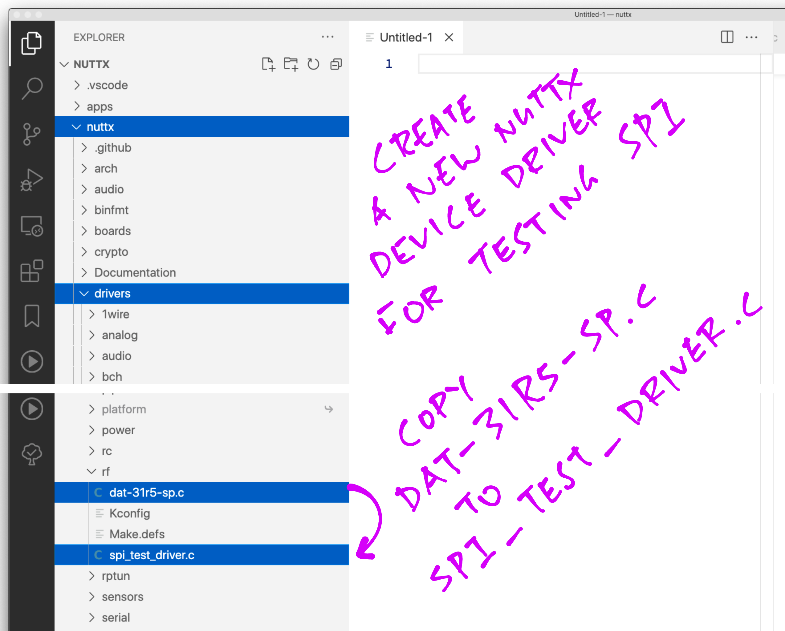
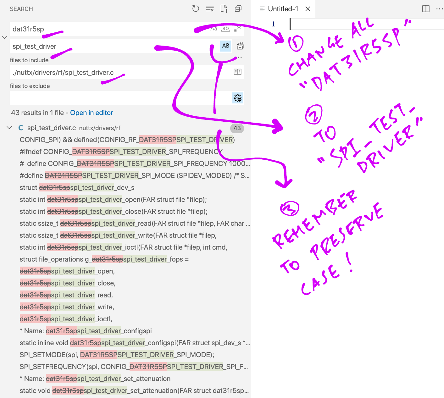
Inside the “spi_test_driver.c” file, search and replace all “dat31r5sp” by “spi_test_driver”
Be sure to Preserve Case!
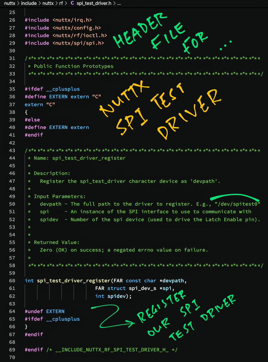
Browse to the “nuttx/nuttx/include/nuttx/rf” folder
Copy the file “dat-31r5-sp.h” and paste it as “spi_test_driver.h”
Inside the “spi_test_driver.h” file, search and replace all “dat31r5sp” by “spi_test_driver”
Remember to Preserve Case!
The Header File should look like this…
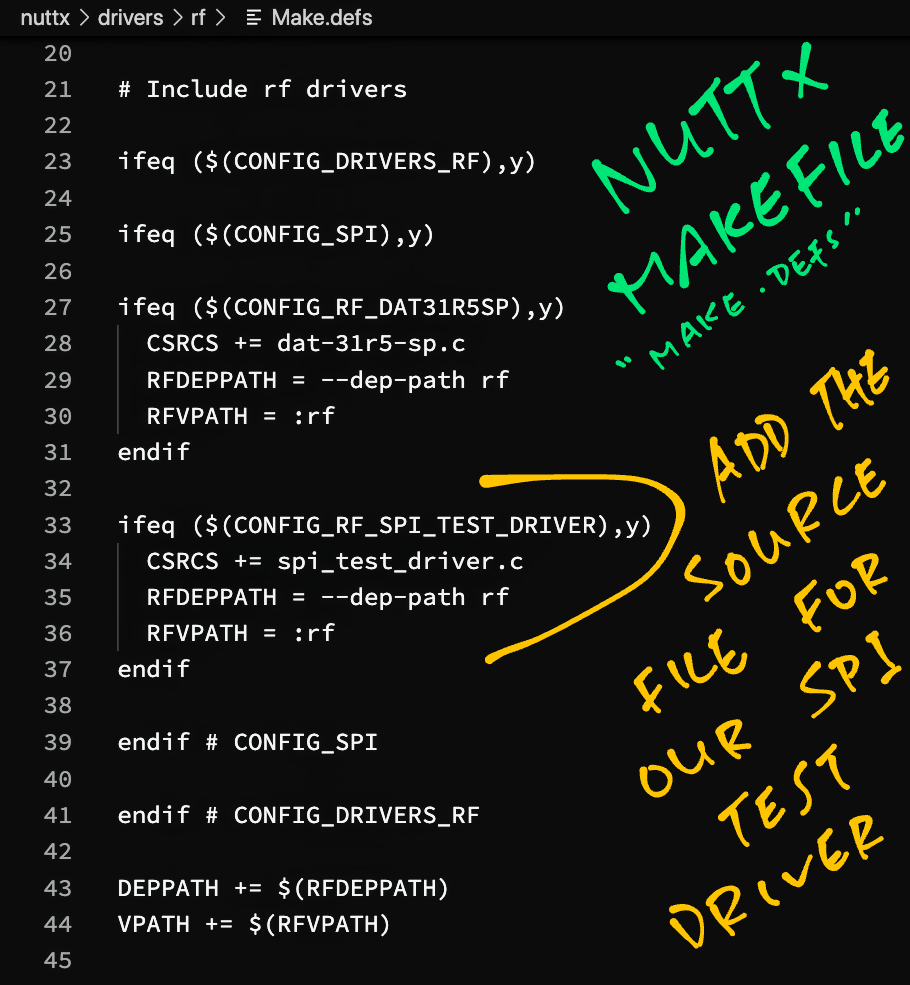
Now we update the Makefile so that NuttX will build our Device Driver…
Browse to the “nuttx/nuttx/drivers/rf” folder
Edit the file “Make.defs”
Insert this section…
ifeq ($(CONFIG_RF_SPI_TEST_DRIVER),y)
  CSRCS += spi_test_driver.c
  RFDEPPATH = --dep-path rf
  RFVPATH = :rf
endif
As shown below…
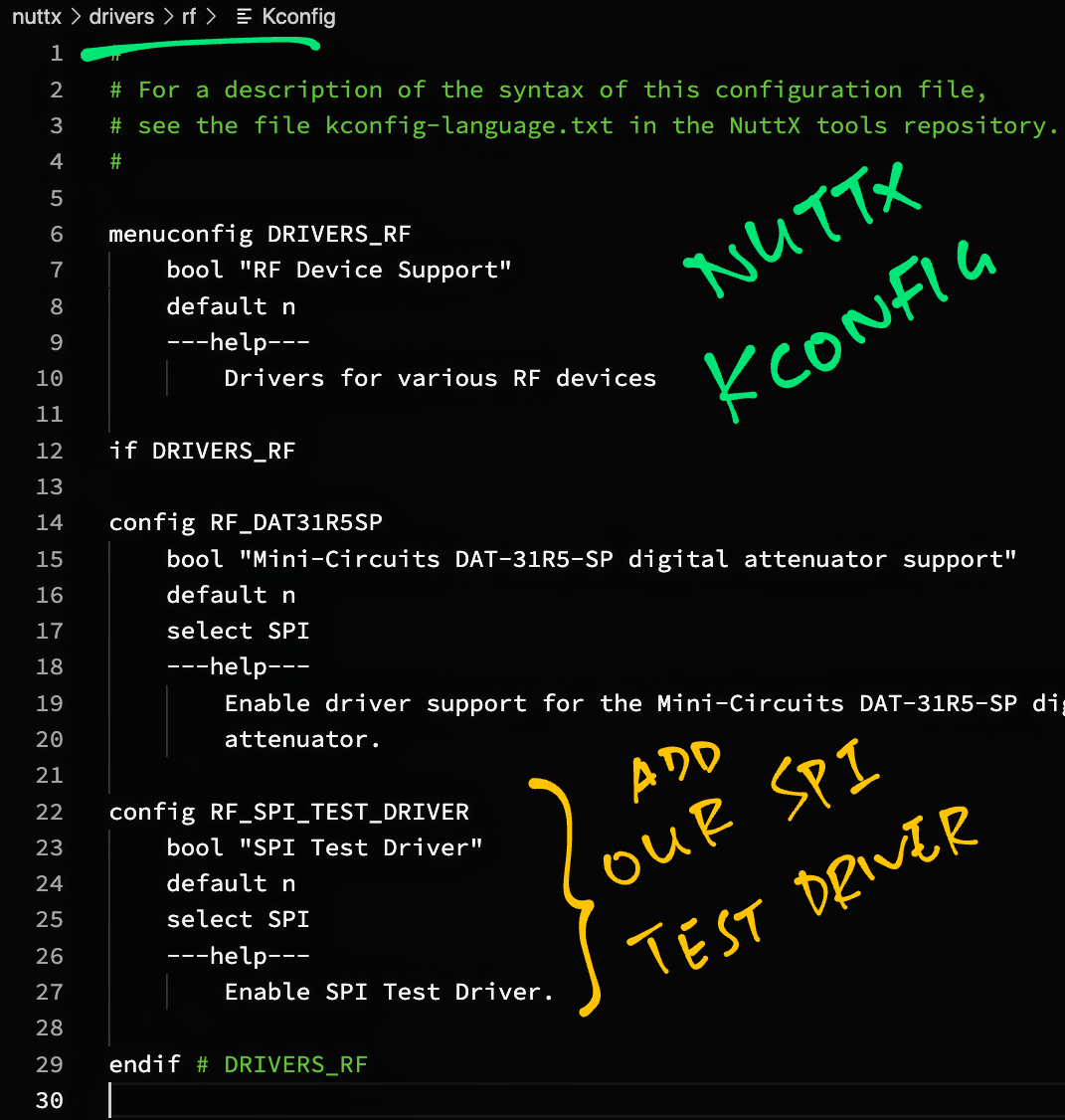
Edit the file “Kconfig”
Insert this section…
config RF_SPI_TEST_DRIVER
    bool "SPI Test Driver"
    default n
    select SPI
    ---help---
        Enable SPI Test Driver.
As shown below…
Enter the following…
## TODO: Change this to the path of our "nuttx" folder
cd nuttx/nuttx

## Preserve the Build Config
cp .config ../config

## Erase the Build Config
make distclean

## For BL602: Configure the build for BL602
./tools/configure.sh bl602evb:nsh

## For PineDio Stack BL604: Configure the build for BL604
./tools/configure.sh bl602evb:pinedio

## For ESP32: Configure the build for ESP32.
## TODO: Change "esp32-devkitc" to our ESP32 board.
./tools/configure.sh esp32-devkitc:nsh

## Restore the Build Config
cp ../config .config

## Edit the Build Config
make menuconfig We enable SPI and our Device Driver as follows…
In menuconfig, select “System Type”
For BL602: Check the box for “BL602 Peripheral Support” → “SPI0”
For ESP32: Check the box for “ESP32 Peripheral Select” → “SPI 2”
Hit “Exit” until the Top Menu appears. (“NuttX/x64_64 Configuration”)
At the Top Menu, select “Device Drivers”
Select “SPI Driver”
Check the box for “SPI Character Driver”
(“SPI Exchange” should already be checked, see pic above)
Hit “Exit” to return to “Device Drivers”
Under “Device Drivers”, check the box for “RF Device Support”
Go inside “RF Device Support”
Check the box for “SPI Test Driver”
Hit “Exit” until the Top Menu appears. (“NuttX/x64_64 Configuration”)
Next we enable SPI logging for easier troubleshooting…
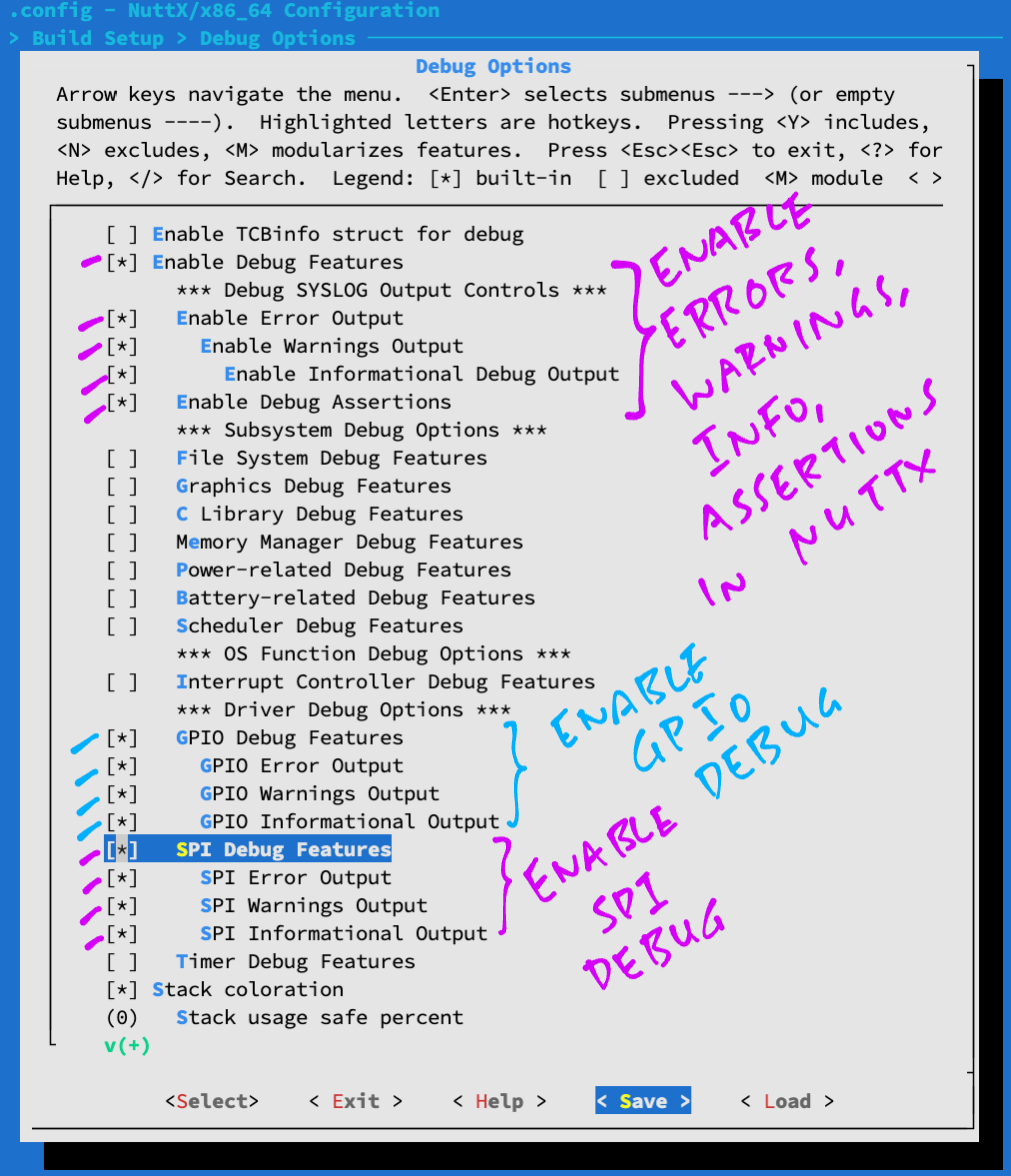
In menuconfig, select “Build Setup” → “Debug Options”
Check the boxes for the following…
Enable Debug Features
Enable Error Output
Enable Warnings Output
Enable Informational Debug Output
Enable Debug Assertions
GPIO Debug Features
GPIO Error Output
GPIO Warnings Output
GPIO Informational Output
SPI Debug Features
SPI Error Output
SPI Warnings Output
SPI Informational Output
For LoRaWAN: Uncheck the following…
Enable Informational Debug Output
GPIO Informational Output
SPI Informational Output
Hit “Save” then “OK” to save the NuttX Configuration to “.config”
Hit “Exit” until menuconfig quits
During NuttX startup, we need to register our Device Driver like so…
Browse to the Board Folder…
For BL602: nuttx/nuttx/boards/ risc-v/bl602/bl602evb
For ESP32: nuttx/nuttx/boards/ xtensa/esp32/esp32-devkitc
(Change “esp32-devkitc” to our ESP32 board)
Edit the Bringup Code…
For BL602: bl602_bringup.c
For ESP32: esp32_bringup.c
Edit the function bl602_bringup() to register our Device Driver as “/dev/spitest0”…
/* Insert this code after the #include block */

#ifdef CONFIG_RF_SPI_TEST_DRIVER
#include <nuttx/rf/spi_test_driver.h>
#endif /* CONFIG_RF_SPI_TEST_DRIVER */

/* End of inserted code */

...

int bl602_bringup(void)
{
  /* Omitted: Existing code in the function */

  /* Insert this code just before the "return" statement */

#ifdef CONFIG_RF_SPI_TEST_DRIVER

  /* Init SPI bus again */

  struct spi_dev_s *spitest = bl602_spibus_initialize(0);
  if (!spitest)
    {
      _err("ERROR: Failed to initialize SPI %d bus\n", 0);
    }

  /* Register the SPI Test Driver */

  ret = spi_test_driver_register("/dev/spitest0", spitest, 0);
  if (ret < 0)
    {
      _err("ERROR: Failed to register SPI Test Driver\n");
    }

#endif /* CONFIG_RF_SPI_TEST_DRIVER */

  /* End of inserted code */

  return ret;
}For ESP32: Edit the function esp32_bringup() and insert the code above. Change “bl602_spibus_initialize(0)” to “esp32_spibus_initialize(2)”. (Like this)
Finally we run the NuttX Firmware and check for our Device Driver…
Build (“make”), flash and run the NuttX Firmware on BL602 or ESP32.
In the NuttX Shell, enter…
ls /devOur Device Driver appears as “/dev/spitest0”.
Congratulations our Device Driver is now running on NuttX!
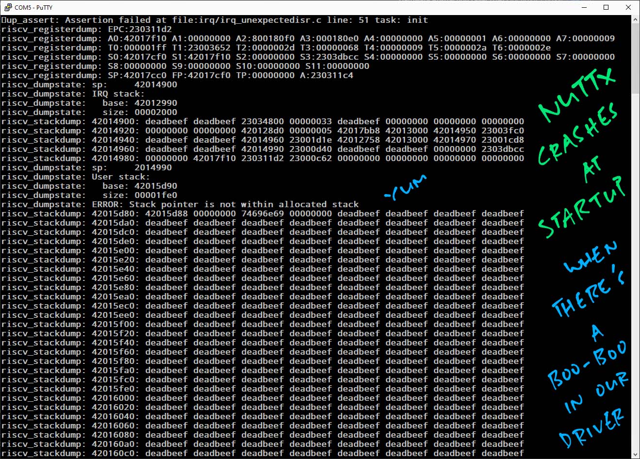
Look what happens if we forget to enable “SPI0” (BL602) or “SPI 2” (ESP32) and NuttX won’t start…
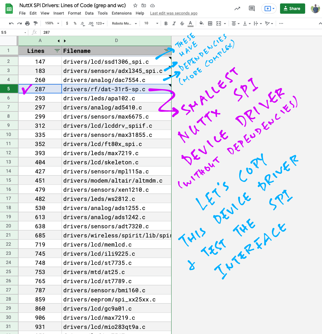
Why did we choose the “dat-31r5-sp” driver for cloning?
We scanned the NuttX SPI Device Drivers (“grep” and “wc”) and picked “dat-31r5-sp” because…
The driver code is simple
(No dependencies on other modules)
It has the fewest lines of code
(Easier to customise)
It’s the only driver in the RF Category
(Quick to modify the Makefile and Kconfig)
Remember to move our driver to the correct category before releasing it!
(For BL602 and ESP32)
This section explains the steps to create a NuttX App named “spi_test”.
(Change “spi_test” to the desired name of our app)
Browse to the “nuttx/apps/examples” folder
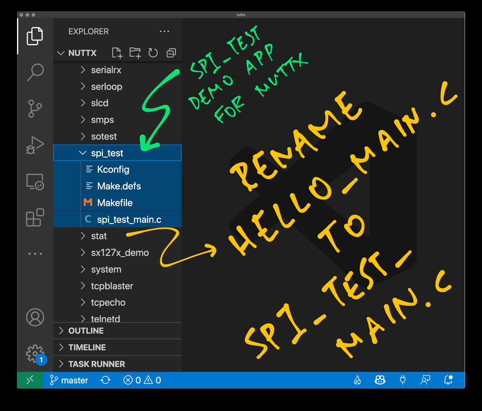
Copy the “hello” subfolder and paste it as “spi_test”
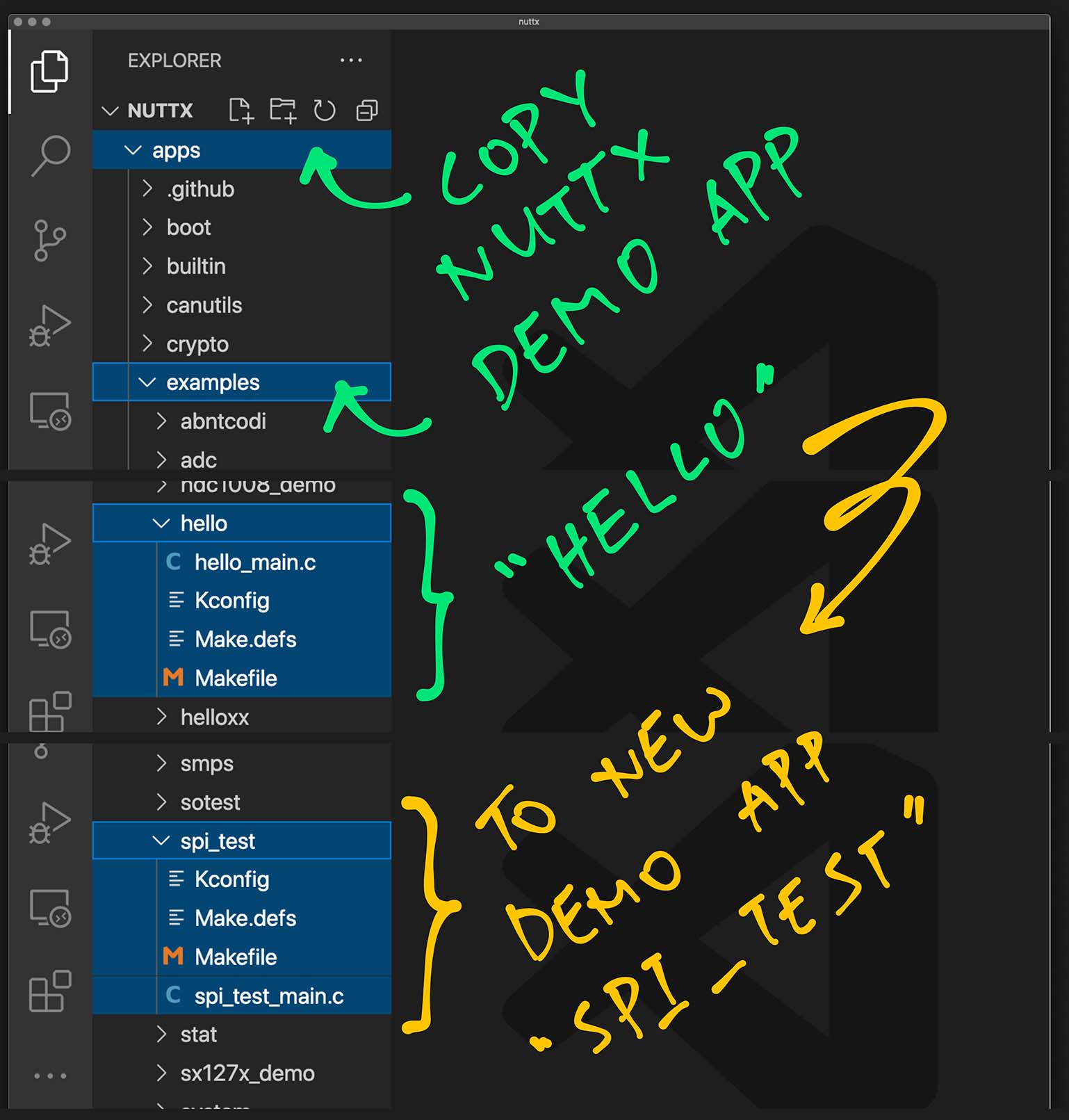
Inside the “spi_test” folder, rename “hello_main.c” to “spi_test_main.c”
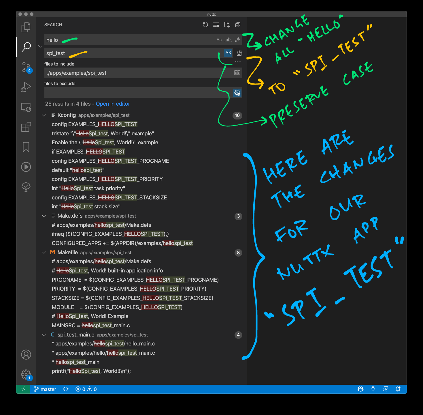
Inside the “spi_test” folder, search and replace all “hello” by “spi_test”
Be sure to Preserve Case!
Enter the following…
## TODO: Change this to the path of our "nuttx" folder
cd nuttx/nuttx

## Preserve the Build Config
cp .config ../config

## Erase the Build Config
make distclean

## For BL602: Configure the build for BL602
./tools/configure.sh bl602evb:nsh

## For PineDio Stack BL604: Configure the build for BL604
./tools/configure.sh bl602evb:pinedio

## For ESP32: Configure the build for ESP32.
## TODO: Change "esp32-devkitc" to our ESP32 board.
./tools/configure.sh esp32-devkitc:nsh

## Restore the Build Config
cp ../config .config

## Edit the Build Config
make menuconfig
Next we enable our app (pic above)…
In menuconfig, select “Application Configuration” → “Examples”
Check the box for “spi_test”
Hit “Save” then “OK” to save the NuttX Configuration to “.config”
Hit “Exit” until menuconfig quits
Finally we run the NuttX Firmware and start our app…
Build (“make”), flash and run the NuttX Firmware on BL602 or ESP32.
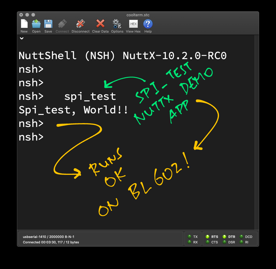
In the NuttX Shell, enter…
spi_testWe should see the output below.
Congratulations we have created the “spi_test” app!
(For BL602 and ESP32)
Below are the steps to build, flash and run NuttX on BL602 and ESP32.
The instructions below will work on Linux (Ubuntu), WSL (Ubuntu) and macOS.
(Instructions for other platforms)
Follow these steps to build NuttX for BL602 or ESP32…
Install the build prerequisites…
Assume that we have downloaded and configured our NuttX code…
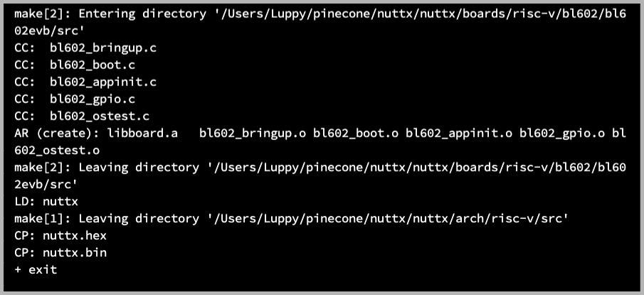
Build NuttX…
makeWe should see…
LD: nuttx
CP: nuttx.hex
CP: nuttx.binFor WSL: Copy the NuttX Firmware to the c:\blflash directory in the Windows File System…
##  /mnt/c/blflash refers to c:\blflash in Windows
mkdir /mnt/c/blflash
cp nuttx.bin /mnt/c/blflash
For WSL we need to run blflash under plain old Windows CMD (not WSL) because it needs to access the COM port.
In case of problems, refer to the NuttX Docs…
For ESP32: See instructions here (Also check out this article)
For BL602: Follow these steps to install blflash…
We assume that our Firmware Binary File nuttx.bin has been copied to the blflash folder.
Set BL602 / BL604 to Flashing Mode and restart the board…
For PineDio Stack BL604:
Set the GPIO 8 Jumper to High (Like this)
Disconnect the USB cable and reconnect
Or use the Improvised Reset Button (Here’s how)
For PineCone BL602:
Set the PineCone Jumper (IO 8) to the H Position (Like this)
Press the Reset Button
For BL10:
Connect BL10 to the USB port
Press and hold the D8 Button (GPIO 8)
Press and release the EN Button (Reset)
Release the D8 Button
For Ai-Thinker Ai-WB2, Pinenut and MagicHome BL602:
Disconnect the board from the USB Port
Connect GPIO 8 to 3.3V
Reconnect the board to the USB port
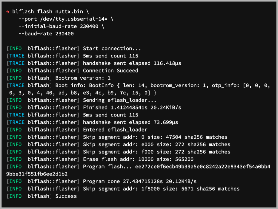
Enter these commands to flash nuttx.bin to BL602 / BL604 over UART…
## For Linux: Change "/dev/ttyUSB0" to the BL602 / BL604 Serial Port
blflash flash nuttx.bin \
  --port /dev/ttyUSB0

## For macOS: Change "/dev/tty.usbserial-1410" to the BL602 / BL604 Serial Port
blflash flash nuttx.bin \
  --port /dev/tty.usbserial-1410 \
  --initial-baud-rate 230400 \
  --baud-rate 230400

## For Windows: Change "COM5" to the BL602 / BL604 Serial Port
blflash flash c:\blflash\nuttx.bin --port COM5For WSL: Do this under plain old Windows CMD (not WSL) because blflash needs to access the COM port.
(Flashing WiFi apps to BL602 / BL604? Remember to use bl_rfbin)
(More details on flashing firmware)
For ESP32: Use Picocom to connect to ESP32 over UART…
picocom -b 115200 /dev/ttyUSB0For BL602: Set BL602 / BL604 to Normal Mode (Non-Flashing) and restart the board…
For PineDio Stack BL604:
Set the GPIO 8 Jumper to Low (Like this)
Disconnect the USB cable and reconnect
Or use the Improvised Reset Button (Here’s how)
For PineCone BL602:
Set the PineCone Jumper (IO 8) to the L Position (Like this)
Press the Reset Button
For BL10:
For Ai-Thinker Ai-WB2, Pinenut and MagicHome BL602:
Disconnect the board from the USB Port
Connect GPIO 8 to GND
Reconnect the board to the USB port
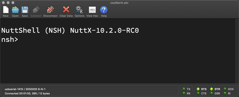
After restarting, connect to BL602 / BL604’s UART Port at 2 Mbps like so…
For Linux:
screen /dev/ttyUSB0 2000000For macOS: Use CoolTerm (See this)
For Windows: Use putty (See this)
Alternatively: Use the Web Serial Terminal (See this)
Press Enter to reveal the NuttX Shell…
NuttShell (NSH) NuttX-10.2.0-RC0
nsh>
Congratulations NuttX is now running on BL602 / BL604!
(More details on connecting to BL602 / BL604)
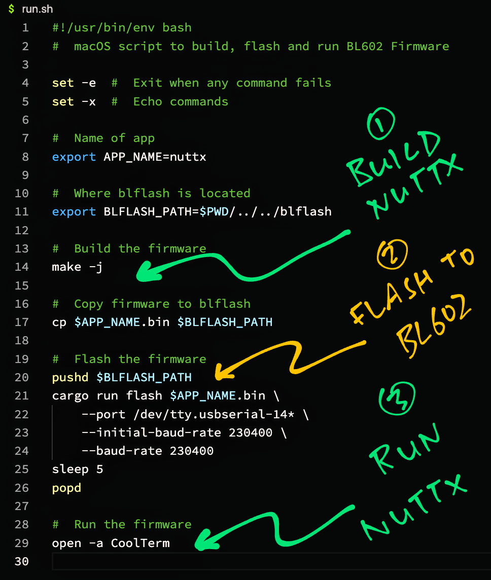
macOS Tip: Here’s the script I use to build, flash and run NuttX on macOS, all in a single step: run.sh
(For BL602 and ESP32)
In this section we dig deep into NuttX OS to understand how the SPI Functions work.
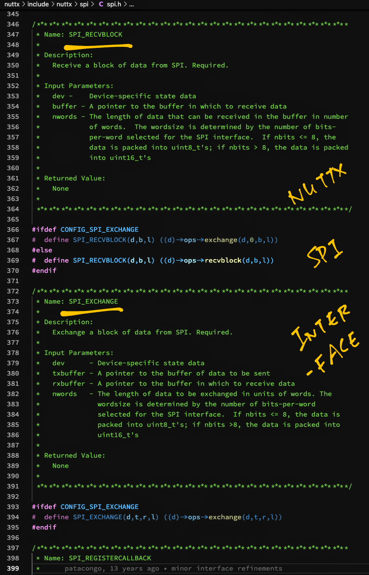
The NuttX SPI Interface (pic above) is defined as C Macros in include/nuttx/spi/spi.h
SPI_LOCK: Lock the SPI Bus for exclusive access
SPI_SELECT: Enable / disable the SPI Chip Select
SPI_SETFREQUENCY: Set the SPI frequency
SPI_SETDELAY: Set the SPI Delays in nanoseconds
SPI_SETMODE: Set the SPI Mode
SPI_SETBITS: Set the number of bits per word (Transfer size)
SPI_HWFEATURES: Set hardware-specific feature flags
SPI_STATUS: Get SPI/MMC status
SPI_CMDDATA: Transfer 9-bit data (like for ST7789 Display)
SPI_SEND: Exchange one word on SPI
SPI_SNDBLOCK: Send a block of data on SPI
SPI_RECVBLOCK: Receive a block of data from SPI
SPI_EXCHANGE: Exchange a block of data from SPI
SPI_REGISTERCALLBACK: Register a callback for media status change
SPI_TRIGGER: Trigger a previously configured DMA transfer
The above SPI Interface is meant to be called by NuttX Device Drivers like so: spi_test_driver.c
/* Write the buffer to the SPI device */

static ssize_t spi_test_driver_write(
  FAR struct file *filep,
  FAR const char *buffer,
  size_t buflen)
{
  /* Get the SPI interface */

  FAR struct inode *inode = filep->f_inode;
  FAR struct spi_test_driver_dev_s *priv = inode->i_private;

  /* Omitted: Lock, configure and select the SPI interface */

  /* Transfer data to SPI interface */

  SPI_EXCHANGE(priv->spi, buffer, recv_buffer, buflen);
SPI_EXCHANGE is defined in the SPI Interface as…
#define SPI_EXCHANGE(d,t,r,l) \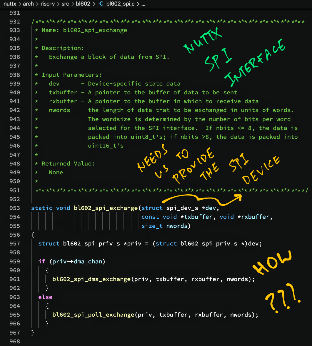
((d)->ops->exchange(d,t,r,l))Which maps to bl602_spi_exchange for BL602…
static void bl602_spi_exchange(
  struct spi_dev_s *dev,
  const void *txbuffer,
  void *rxbuffer,
  size_t nwords) {
  ...
(Or esp32_spi_exchange for ESP32)
Note that the SPI Interface requires an SPI Device (spi_dev_s) to be passed in.
Which is available to NuttX Device Drivers.
Can a NuttX App call the SPI Interface directly like this?
Nope this won’t work, because NuttX Apps can’t access the SPI Device (spi_dev_s).
Let’s dig into NuttX OS and find out why.
In a NuttX App we may open the SPI Port “/dev/spi0” to get a File Descriptor…
int fd = open("/dev/spi0", O_RDWR);How is the File Descriptor linked to the SPI Device (spi_dev_s)?
Well we use the File Descriptor to execute File Operations: read(), write(), ioctl(), …
Tracing through the NuttX Virtual File System, we see that ioctl() maps the File Descriptor to a File Struct…
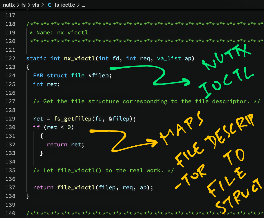
The File Struct contains a Private Pointer to the SPI Driver (spi_driver_s)…
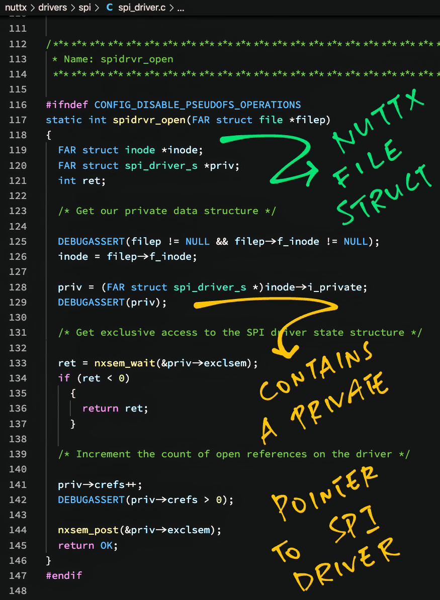
The SPI Driver (spi_driver_s) contains the SPI Device (spi_dev_s)…
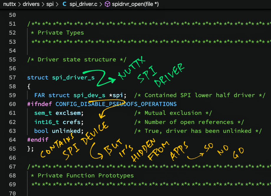
Which is what we need for calling the SPI Interface!
But sadly the SPI Device is private to NuttX OS and we can’t access it from the NuttX App.
That’s why we wrote our own SPI Test Driver (which runs inside NuttX OS) to get access to the SPI Device and call the SPI Interface.
(By calling the SPI Test Driver from our SPI Test App)
In summary, NuttX maps a File Descriptor to SPI Device as follows…
File Descriptor → File Struct → SPI Driver (spi_driver_s) → SPI Device (spi_dev_s)
(For BL602 only)
BL602 has an SPI issue that affects both NuttX and BL602 IoT SDK: MISO and MOSI pins are swapped, contrary to the Pin Descriptions in the BL602 Reference Manual.
In this section we…
Reproduce the issue on NuttX
Propose a fix for NuttX
Test the fix
The fix has been merged into NuttX…
(Thank you NuttX Maintainers! 🙂 )
Note that the SPI Mode needs to be 1 (instead of 0) for the SPI interface to operate correctly…
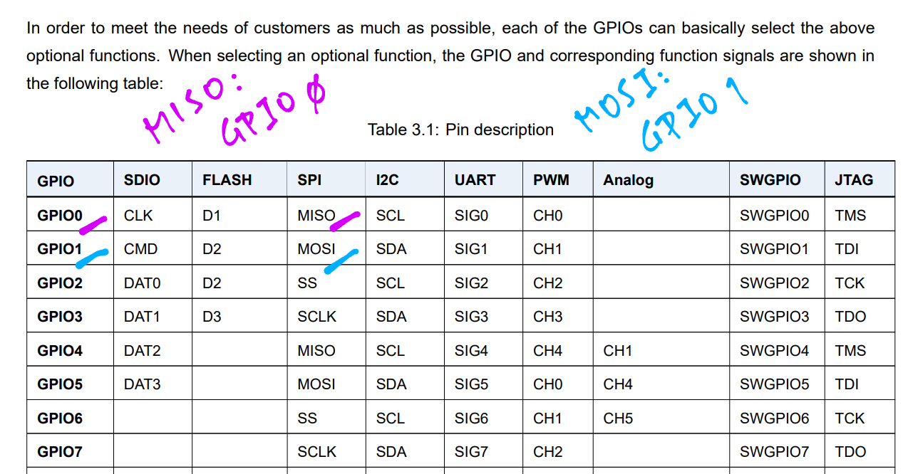
The default SPI Pins for NuttX are defined in board.h
/* SPI Configuration */

#define BOARD_SPI_CS   (GPIO_INPUT | GPIO_PULLUP | GPIO_FUNC_SPI | GPIO_PIN2)
#define BOARD_SPI_MOSI (GPIO_INPUT | GPIO_PULLUP | GPIO_FUNC_SPI | GPIO_PIN1)
#define BOARD_SPI_MISO (GPIO_INPUT | GPIO_PULLUP | GPIO_FUNC_SPI | GPIO_PIN0)
#define BOARD_SPI_CLK  (GPIO_INPUT | GPIO_PULLUP | GPIO_FUNC_SPI | GPIO_PIN3)
This says that MISO is GPIO 0, MOSI is GPIO 1.
This is consistent with the Pin Description Table from BL602 Reference Manual (Version 1.2, 17 Dec 2020, page 26)
We test the SPI Port with an SPI Test Driver: spi_test_driver.c
/* Write the buffer to the SPI device */

static ssize_t spi_test_driver_write(
  FAR struct file *filep,
  FAR const char *buffer,
  size_t buflen)
{
  ...
  /* Transmit buffer to SPI device and receive the response */

  SPI_EXCHANGE(priv->spi, buffer, recv_buffer, buflen);
  recv_buffer_len = buflen;
Which is called by an SPI Test App: spi_test_main.c
int main(int argc, FAR char *argv[])
{
  /* Open SPI Test Driver */

  int fd = open("/dev/spitest0", O_RDWR);
  assert(fd >= 0);

  /* Write to SPI Test Driver */

  static char data[] = "Hello World";
  int bytes_written = write(fd, data, sizeof(data));
  assert(bytes_written == sizeof(data));
We connect a Logic Analyser to PineCone BL602 and verify the SPI output…
| Logic Analyser | BL602 Pin |
|---|---|
| MOSI | GPIO 1 |
| MISO | GPIO 0 |
| SCK | GPIO 3 |
| CS | GPIO 2 |
| GND | GND |
Logic Analyser shows that MISO and MOSI are swapped…
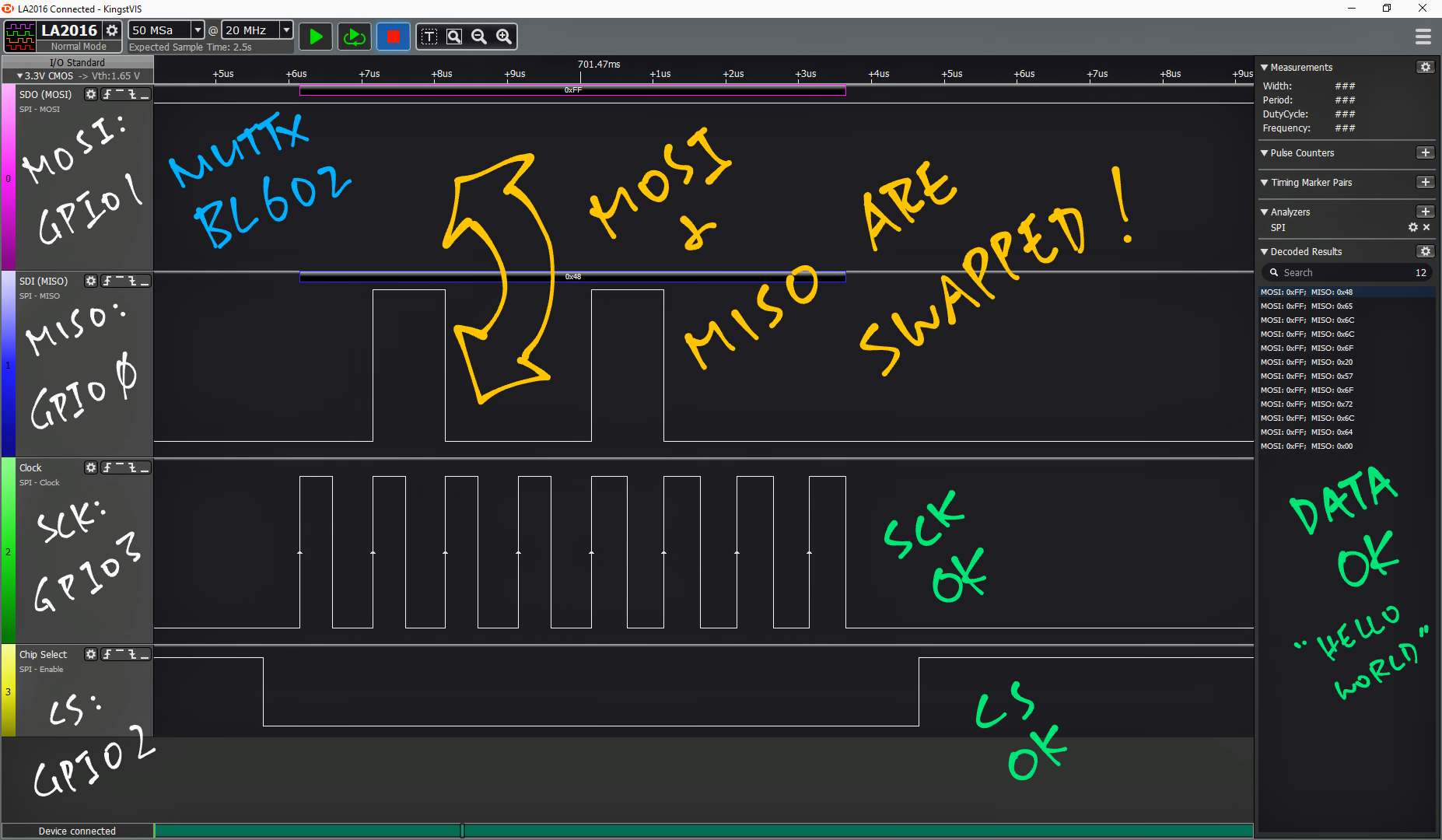
Let’s examine the proposed fix for the issue.
The same issue happens in BL602 IoT SDK…
On BL602 IoT SDK we fix this issue by calling GLB_Swap_SPI_0_MOSI_With_MISO() to swap the MISO and MOSI pins…
/****************************************************************************//**
 * @brief  swap SPI0 MOSI with MISO
 *
 * @param  newState: ENABLE or DISABLE
 *
 * @return SUCCESS or ERROR
 *
*******************************************************************************/
BL_Err_Type GLB_Swap_SPI_0_MOSI_With_MISO(BL_Fun_Type newState)
{
    uint32_t tmpVal = 0;

    tmpVal=BL_RD_REG(GLB_BASE,GLB_PARM);
    tmpVal=BL_SET_REG_BITS_VAL(tmpVal,GLB_REG_SPI_0_SWAP,newState);
    BL_WR_REG(GLB_BASE,GLB_PARM,tmpVal);

    return SUCCESS;
}This function swaps MISO and MOSI by setting the GLB Hardware Register GLB_PARM at bit GLB_REG_SPI_0_SWAP.
For NuttX we propose to port this function as bl602_swap_spi_0_mosi_with_miso() in arch/risc-v/src/bl602/bl602_spi.c
/****************************************************************************
 * Name: bl602_swap_spi_0_mosi_with_miso
 *
 * Description:
 *   Swap SPI0 MOSI with MISO
 *
 * Input Parameters:
 *   swap      - Non-zero to swap MOSI and MISO
 *
 * Returned Value:
 *   None
 *
 ****************************************************************************/

static void bl602_swap_spi_0_mosi_with_miso(uint8_t swap)
{
  if (swap)
    {
      modifyreg32(BL602_GLB_GLB_PARM, 0, GLB_PARM_REG_SPI_0_SWAP);
    }
  else
    {
      modifyreg32(BL602_GLB_GLB_PARM, GLB_PARM_REG_SPI_0_SWAP, 0);
    }
}The function above will be called by bl602_spi_init() in arch/risc-v/src/bl602/bl602_spi.c to swap MISO and MOSI during startup…
/****************************************************************************
 * Name: bl602_spi_init
 *
 * Description:
 *   Initialize bl602 SPI hardware interface
 *
 * Input Parameters:
 *   dev      - Device-specific state data
 *
 * Returned Value:
 *   None
 *
 ****************************************************************************/

static void bl602_spi_init(struct spi_dev_s *dev)
{
  struct bl602_spi_priv_s *priv = (struct bl602_spi_priv_s *)dev;
  const struct bl602_spi_config_s *config = priv->config;

  /* Initialize the SPI semaphore that enforces mutually exclusive access */

  nxsem_init(&priv->exclsem, 0, 1);

  bl602_configgpio(BOARD_SPI_CS);
  bl602_configgpio(BOARD_SPI_MOSI);
  bl602_configgpio(BOARD_SPI_MISO);
  bl602_configgpio(BOARD_SPI_CLK);

  /* set master mode */

  bl602_set_spi_0_act_mode_sel(1);

  /* swap MOSI with MISO to be consistent with BL602 Reference Manual */

bl602_swap_spi_0_mosi_with_miso(1);After applying the fix, we see that the MOSI output is now correct…
As for MISO input, we tested with PineCone BL602 connected to Semtech SX1262. We verified that the register data was read correctly over SPI…
We have also tested the fix with PineDio Stack BL604 and its onboard SX1262…
The fix has been merged into NuttX…
(Thank you NuttX Maintainers! 🙂 )
Note that the SPI Mode needs to be 1 (instead of 0) for our test to succeed…
(For BL602 only)
Due to an SPI Mode Quirk in BL602, we configure BL602 to talk to Semtech SX1262 with SPI Mode 1 (instead of Mode 0).
(Which is quirky because SX1262 supports Mode 0, not Mode 1)
This is defined in spi_test_driver.c
/* For BL602 we use SPI Mode 1 instead of Mode 0 due to SPI quirk */

#ifdef CONFIG_BL602_SPI0
#define SPI_TEST_DRIVER_SPI_MODE (SPIDEV_MODE1) /* SPI Mode 1: Workaround for BL602 */
#else
#define SPI_TEST_DRIVER_SPI_MODE (SPIDEV_MODE0) /* SPI Mode 0: CPOL=0,CPHA=0 */
#endif /* CONFIG_BL602_SPI0 */
Let’s watch what happens if we use SPI Mode 0 (instead of Mode 1) when BL602 talks to Semtech SX1262…
#define SPI_TEST_DRIVER_SPI_MODE (SPIDEV_MODE0) /* SPI Mode 0: CPOL=0,CPHA=0 */We run spi_test2_main.c to Read Register 0x08 from SX1262 over SPI…
/* Transmit command to SX1262: Read Register 8 */

static char read_reg[] = { 0x1d, 0x00, 0x08, 0x00, 0x00 };
bytes_written = write(fd, read_reg, sizeof(read_reg));
assert(bytes_written == sizeof(read_reg));

/* Read response from SX1262 */

bytes_read = read(fd, rx_data, sizeof(rx_data));
assert(bytes_read == sizeof(read_reg));

/* Show the received register value */

printf("\nSX1262 Register 8 is 0x%02x\n", rx_data[4]);
We expect the value of Register 0x08 to be 0x80.
With SPI Mode 0, the register value received over SPI is incorrect (0x5A)…
Read Register 8: received
  a8 a8 00 43 5a
SX1262 Register 8 is 0x5a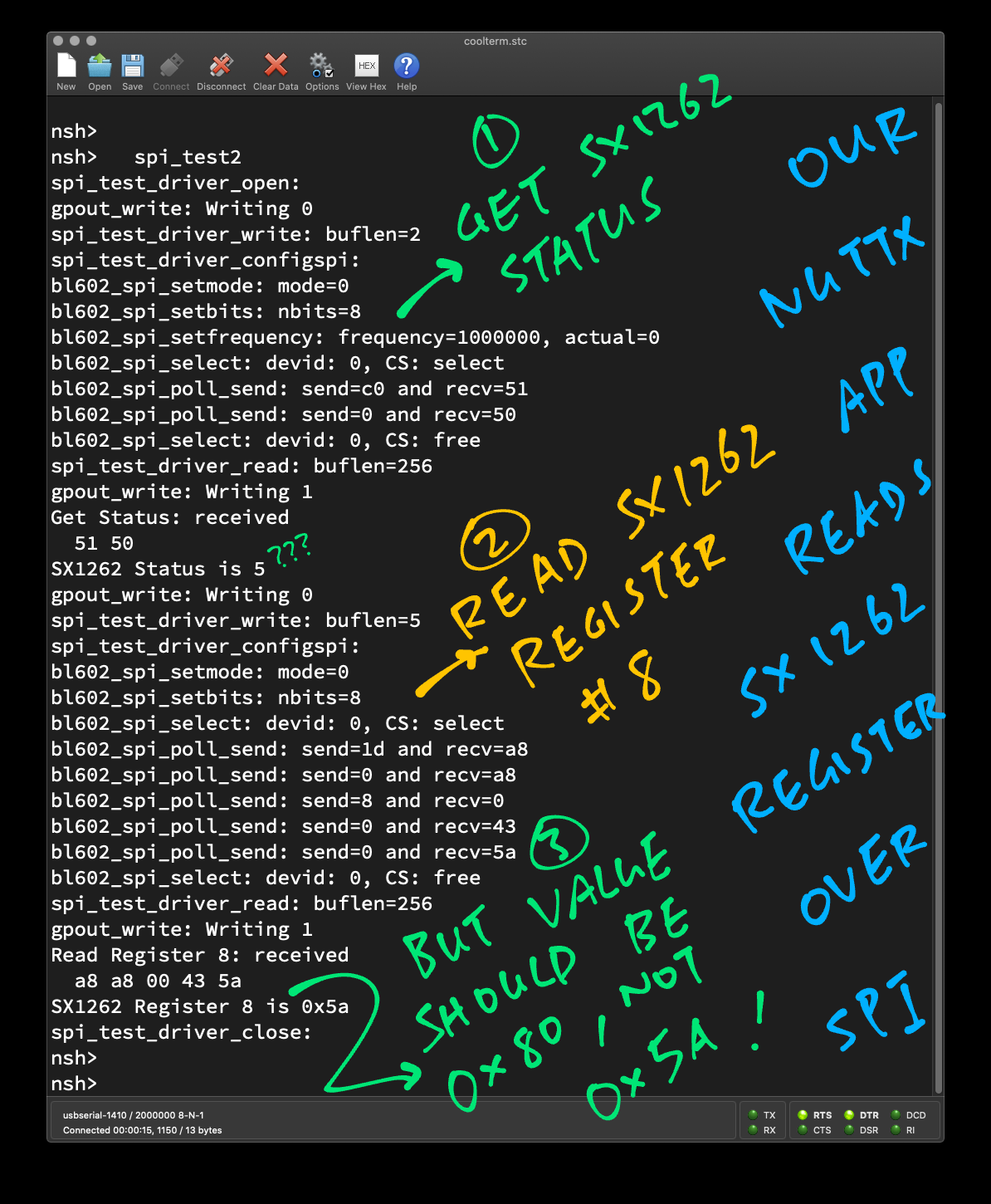
When we switch to SPI Mode 1, we get the correct value: 0x80…
Read Register 8: received
  a8 a8 a8 a8 80
SX1262 Register 8 is 0x80
This SPI Mode Quirk has been observed on BL602 IoT SDK when tested with…
ST7789 Display Controller (SPI Mode 3)
This is why we always use SPI Mode 1 instead of Mode 0 on BL602.
UPDATE: BL602 talks to SPI Devices in SPI Mode 1 or Mode 3, depending on whether the MISO / MOSI Pins are swapped. (See this)