📝 16 Feb 2021
In our last article we configured PineCone BL602 to connect to a simple SPI Peripheral: BME280 Sensor. (See this)
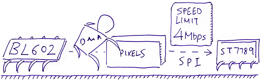
Today we shall connect PineCone BL602 / Pinenut / Any BL602 Board to a more powerful SPI Peripheral: ST7789 Display Controller.
We’ll be using the open-source LVGL Graphics Library to render text and graphics to our ST7789 Display.
(Yep LVGL runs on RISC-V!)
The Demo Firmware in this article will run on PineCone, Pinenut and Any BL602 Board.
Watch the Demo Video on YouTube
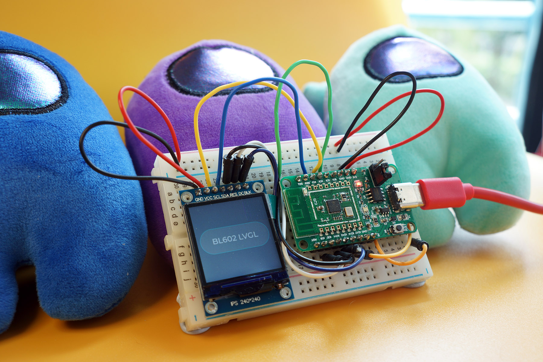
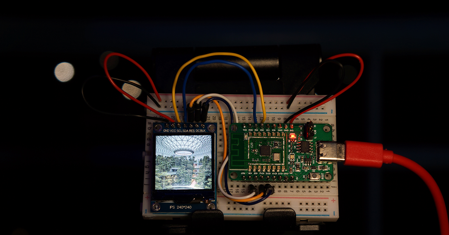
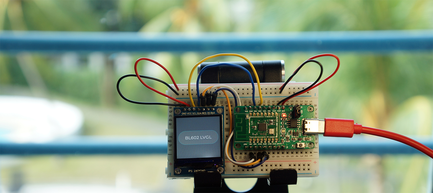
PineCone BL602 RISC-V Board rendering text and graphics on ST7789 SPI Display with LVGL Graphics Library
Let’s inspect the (non-obvious) pins on our ST7789 Display…
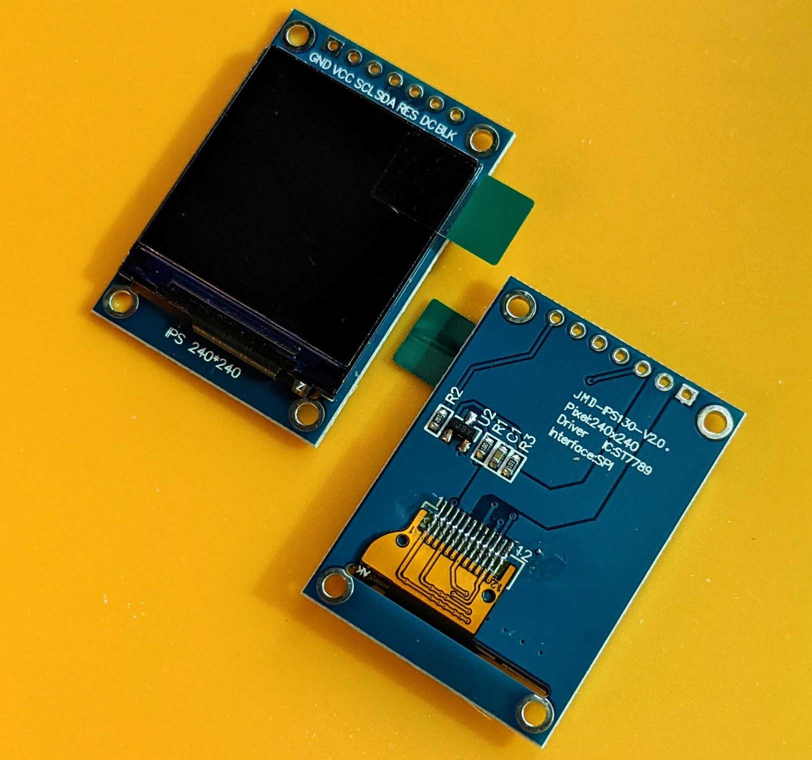
(Make sure that it says Interface SPI)
SCL: Clock Pin. This goes to the SPI Clock Pin on BL602.
SDA: Data Pin. This goes to the SPI Serial Data Out Pin on BL602. (Formerly MOSI)
RES: Reset Pin. We’ll toggle this pin with BL602 GPIO to force a Hardware Reset.
DC: Data / Command Pin. We set this pin to Low when sending a command on the Data Pin. And to High when sending data on the Data Pin.
BLK: Backlight Pin. We set this pin to High to switch on the backlight.
Connect BL602 to ST7789 as follows…
| BL602 Pin | ST7789 SPI | Wire Colour |
|---|---|---|
GPIO 1 | Do Not Connect (MISO) | |
GPIO 2 | Do Not Connect | |
GPIO 3 | SCL | Yellow |
GPIO 4 | SDA (MOSI) | Blue |
GPIO 5 | DC | White |
GPIO 11 | RST | Orange |
GPIO 12 | BLK | Purple |
GPIO 14 | Do Not Connect | |
3V3 | 3.3V | Red |
GND | GND | Black |
Why are Pins 1, 2 and 14 unused?
GPIO 1 is SPI Serial Data In on BL602. (Formerly MISO)
We won’t be reading data from the ST7789 Display, so this pin is unused.
GPIO 2 is the Unused SPI Chip Select on BL602.
We won’t use this pin because we’ll control Chip Select ourselves on GPIO 14. (See this)
GPIO 14 is the Actual SPI Chip Select on BL602.
According to the last article, we’ll be controling Chip Select ourselves on GPIO 14.
However our ST7789 Display doesn’t have a Chip Select Pin, so this pin is unused.
We’re running out of BL602 Pins… Can we reduce the number of pins connected to ST7789?
We may connect ST7789’s Backlight Pin to 3V3. But we lose the ability to switch off the backlight and reduce power consumption. (See this)
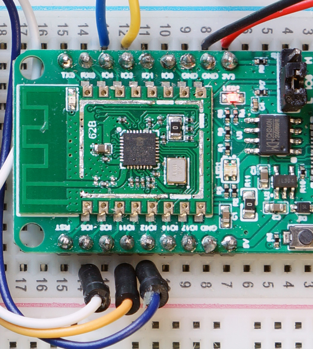
PineCone BL602 Pins connected to ST7789: 3 (Yellow), 4 (Blue), 5 (White), 11 (Orange) and 12 (Purple)
To initialise BL602’s SPI Port, we used the same code as the previous article, except for two modifications.
Here’s how our function test_display_init initialises the SPI Port: demo.c
/// Command to init the display
static void test_display_init(char *buf, int len, int argc, char **argv) {
    //  Configure the SPI Port
    int rc = spi_init(
        &spi_device, //  SPI Device
        SPI_PORT,    //  SPI Port
        0,           //  SPI Mode: 0 for Controller (formerly Master)
        3,           //  SPI Polarity Phase: Must be 3 for ST7789 (CPOL=1, CPHA=1)
        4 * 1000 * 1000,  //  SPI Frequency (4 MHz, reduce this in case of problems)
        2,   //  Transmit DMA Channel
        3,   //  Receive DMA Channel
        3,   //  (Yellow) SPI Clock Pin
        2,   //  (Unused) SPI Chip Select Pin (Unused because we control GPIO 14 ourselves as Chip Select Pin. This must NOT be set to 14, SPI will override our GPIO!)
        1,   //  (Green)  SPI Serial Data In Pin  (formerly MISO) (Unused for ST7789)
        4    //  (Blue)   SPI Serial Data Out Pin (formerly MOSI)
    );
assert(rc == 0);Here are the modifications from the previous article…
SPI Polarity Phase is 3 (Polarity 1, Phase 1): This is needed specifically for ST7789’s SPI Interface
(Be careful with SPI Phase on BL602… It doesn’t work the way we expect. See this)
SPI Frequency is 4 MHz: Why bump up the SPI Frequency? To blast pixels the fastest speed possible to ST7789!
BL602 supports up to 40 MHz for SPI Frequency… But 4 MHz is the maximum SPI Frequency that was tested OK for my setup. (Beyond that the SPI Transfer hangs)
If you’re having problems with SPI Transfers (like hanging), reduce the SPI Frequency. (Lowest SPI Frequency is 200 kHz)
This part is also specific to ST7789…
Configure the GPIO Pins
Initialise the Display Controller
Switch on the backlight
    //  Configure the GPIO Pins, init the display controller
    //  and switch on backlight
    rc = init_display();
    assert(rc == 0);
}
We’ll explain init_display in a while.
SPI_PORT and spi_device are unchanged…
/// Use SPI Port Number 0
#define SPI_PORT   0

/// SPI Device Instance. Used by display.c
spi_dev_t spi_device;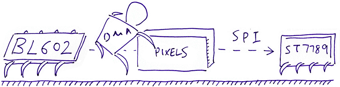
For transmitting SPI Data to ST7789, the code looks highly similar to our previous article. (Except that we’re not interested in the data received)
Here’s how our function transmit_spi transmits data to ST7789: display.c
/// Write to the SPI port. `data` is the array of bytes to be written. `len` is the number of bytes.
static int transmit_spi(const uint8_t *data, uint16_t len) {
    //  Clear the receive buffer
    memset(&spi_rx_buf, 0, sizeof(spi_rx_buf));
We pass to transmit_spi the array of bytes to be written (data) and the number of bytes to be written (len).
We prepare the SPI Transfer the same way…
    //  Prepare SPI Transfer
    static spi_ioc_transfer_t transfer;
    memset(&transfer, 0, sizeof(transfer));
    transfer.tx_buf = (uint32_t) data;        //  Transmit Buffer
    transfer.rx_buf = (uint32_t) spi_rx_buf;  //  Receive Buffer
    transfer.len    = len;                    //  How many bytes
(We’ll explain spi_rx_buf in a while)
We control the Chip Select Pin via GPIO the same way…
    //  Select the SPI Peripheral (not used for ST7789)
    int rc = bl_gpio_output_set(DISPLAY_CS_PIN, 0);
    assert(rc == 0);
We execute the SPI Transfer and wait for it to complete…
    //  Execute the SPI Transfer with the DMA Controller
    rc = hal_spi_transfer(
        &spi_device,  //  SPI Device
        &transfer,    //  SPI Transfers
        1             //  How many transfers (Number of requests, not bytes)
    );
    assert(rc == 0);

    //  DMA Controller will transmit and receive the SPI data in the background.
    //  hal_spi_transfer will wait for the SPI Transfer to complete before returning.
Finally we flip the Chip Select Pin to end the SPI Transfer…
    //  Now that we're done with the SPI Transfer...

    //  De-select the SPI Peripheral (not used for ST7789)
    rc = bl_gpio_output_set(DISPLAY_CS_PIN, 1);
    assert(rc == 0);
    return 0;
}
We’re using the same Pin 14 as the Chip Select Pin: demo.h
/// Use GPIO 14 as SPI Chip Select Pin (Unused for ST7789 SPI)
#define DISPLAY_CS_PIN 14
The Chip Select Pin is not used by the ST7789 Display that we have chosen… But other ST7789 Displays may use it.
(Like the one in PineTime Smartwatch)
What’s spi_rx_buf in the SPI Transfer?
Remember that the BL602 SPI Hardware Abstraction Layer (HAL) only executes SPI Transfers… Every SPI Transmit Request must be paired with an SPI Receive Request.
We’re not really interested in receiving data from ST7789, but we need to provide an SPI Receive Buffer anyway: spi_rx_buf
That’s why we set spi_rx_buf as the SPI Receive Buffer for our SPI Transfer…
//  Prepare SPI Transfer
transfer.tx_buf = (uint32_t) data;        //  Transmit Buffer
transfer.rx_buf = (uint32_t) spi_rx_buf;  //  Receive Buffer
transfer.len    = len;                    //  How many bytes
spi_rx_buf is defined in display.c
/// SPI Receive Buffer. We don't actually receive data, but SPI Transfer needs this.
/// Contains 10 rows of 240 pixels of 2 bytes each (16-bit colour).
static uint8_t spi_rx_buf[
    BUFFER_ROWS        //  10 rows of pixels
    * COL_COUNT        //  240 columns of pixels per row
    * BYTES_PER_PIXEL  //  2 bytes per pixel
];
We limit each SPI Transfer to 10 rows of pixels. More about this later.
Now that we have our SPI Transmit Function transmit_spi, let’s call it to send some ST7789 Commands!
What’s inside an ST7789 Command?
An ST7789 Command consists of…
1 byte for the Command Code, followed by…
0 or more bytes for the Command Parameters
We transmit an ST7789 Command by calling write_command…
//  Define the ST7789 Command Code (1 byte: 0x33)
#define VSCRDER  0x33

//  Define the ST7789 Command Parameters (6 bytes)
static const uint8_t VSCRDER_PARA[] = { 0x00, 0x00, 0x14, 0x00, 0x00, 0x00 };

//  Transmit the ST7789 Command
write_command(
    VSCRDER,              //  Command Code (1 byte)
    VSCRDER_PARA,         //  Command Parameters (6 bytes)
    sizeof(VSCRDER_PARA)  //  Number of parameters (6)
);
There’s a special way to transmit Command Codes and Parameters to ST7789…
Why does ST7789 need a Data / Command Pin (Pin 5)?
Because…
We set Data / Command Pin to Low when transmitting the Command Code
We set Data / Command Pin to High when transmitting the Command Parameters
What???
Yep ST7789 is a little unique (and somewhat inefficient)… We need to flip the Data / Command Pin when transmitting an ST7789 Command and its Parameters.
Here’s how write_command transmits the Command Code and Parameters: display.c
/// Transmit ST7789 command and parameters. `params` is the array of
/// parameter bytes, `len` is the number of parameters.
int write_command(uint8_t command, const uint8_t *params, uint16_t len) {
    //  Set Data / Command Pin to Low to tell ST7789 this is a command
    int rc = bl_gpio_output_set(DISPLAY_DC_PIN, 0);
    assert(rc == 0);
Here we call BL602 GPIO to set the Data / Command Pin to Low.
Then we transmit the Command Code (1 byte)…
    //  Transmit the command byte
    rc = transmit_spi(&command, 1);
    assert(rc == 0);
Next we transmit the Command Parameters by calling write_data…
    //  Transmit the parameters as data bytes
    if (params != NULL && len > 0) {
        rc = write_data(params, len);
        assert(rc == 0);
    }
    return 0;
}
As we expect, write_data flips the Data / Command Pin to High: display.c
/// Transmit data to ST7789. `data` is the array of bytes to be transmitted, `len` is the number of bytes.
int write_data(const uint8_t *data, uint16_t len) {
    //  Set Data / Command Pin to High to tell ST7789 this is data
    int rc = bl_gpio_output_set(DISPLAY_DC_PIN, 1);
    assert(rc == 0);
Then it transmits the Command Parameters…
    //  Transmit the data bytes
    rc = transmit_spi(data, len);
    assert(rc == 0);
    return 0;
}
We’ll be calling write_command very often… So yes the Data / Command Pin will be flipped many many times.
Let’s watch how we call write_command…
The ST7789 Display Controller is highly versatile. It will let you flip it, reverse it, even do the “Fallen Lorry”… Without changing the rendering code!
ST7789 supports four Display Orientations…
/// ST7789 Orientation. From https://github.com/almindor/st7789/blob/master/src/lib.rs#L42-L52
#define Portrait         0x00  //  No inverting
#define Landscape        0x60  //  Invert column and page/column order
#define PortraitSwapped  0xC0  //  Invert page and column order
#define LandscapeSwapped 0xA0  //  Invert page and page/column order
We set the Display Orientation like so…
//  Set orientation to Portrait
set_orientation(Portrait);
set_orientation calls write_command (which we have seen earlier) to send the ST7789 Command (Memory Data Access Control) over SPI: display.c
/// ST7789 Colour Settings
#define RGB      1  //  Display colours are RGB

/// ST7789 Command for Memory Data Access Control.
/// From https://github.com/almindor/st7789/blob/master/src/instruction.rs
#define MADCTL   0x36

/// Set the display orientation: Portrait, Landscape, PortraitSwapped or LandscapeSwapped
static int set_orientation(uint8_t orientation) {
    //  Memory Data Access Control (ST7789 Datasheet Page 215)
    if (RGB) {
        uint8_t orientation_para[1] = { orientation };
        int rc = write_command(MADCTL, orientation_para, 1);
        assert(rc == 0);
    } else {
        uint8_t orientation_para[1] = { orientation | 0x08 };
        int rc = write_command(MADCTL, orientation_para, 1);
        assert(rc == 0);
    }
    return 0;
}
We’ll be seeing more write_command in a while… Brace ourselves!
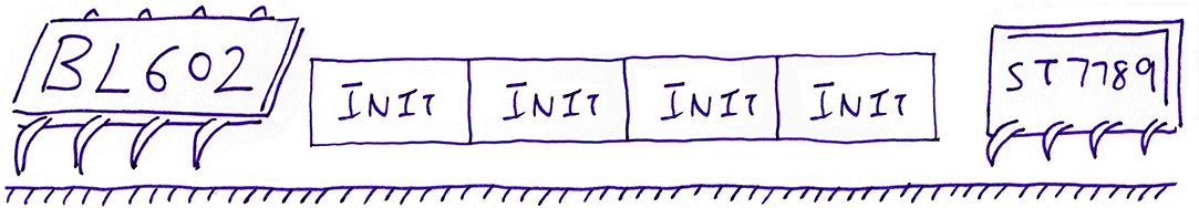
What’s the Hardest Thing about ST7789?
Initialising the ST7789 Display correctly!
It takes EIGHT commands to initialise ST7789… One wrong parameter and nothing appears!
Before we watch the 8 tortuous ST7789 initialisation commands, let’s meet our cast of ST7789 Pins: demo.h
/// Use GPIO 5 as ST7789 Data/Command Pin (DC)
#define DISPLAY_DC_PIN 5

/// Use GPIO 11 as ST7789 Reset Pin (RST)
#define DISPLAY_RST_PIN 11

/// Use GPIO 12 as ST7789 Backlight Pin (BLK)
#define DISPLAY_BLK_PIN 12

/// Use GPIO 14 as SPI Chip Select Pin (Unused for ST7789 SPI)
#define DISPLAY_CS_PIN 14
We’ve met these pins earlier when we connected BL602 to ST7789: Data / Command, Reset, Backlight and Chip Select.
Now we peek behind the scenes of init_display, our function that initialises the display: display.c
/// Initialise the ST7789 display controller.
/// Based on https://github.com/almindor/st7789/blob/master/src/lib.rs
int init_display(void) {
    //  Assume that SPI port 0 has been initialised.
    //  Configure Chip Select, Data/Command, Reset, Backlight pins as GPIO Pins
    GLB_GPIO_Type pins[4];
    pins[0] = DISPLAY_CS_PIN;
    pins[1] = DISPLAY_DC_PIN;
    pins[2] = DISPLAY_RST_PIN;
    pins[3] = DISPLAY_BLK_PIN;
    BL_Err_Type rc2 = GLB_GPIO_Func_Init(
        GPIO_FUN_SWGPIO,  //  Configure the pins as GPIO
        pins,             //  Pins to be configured
        sizeof(pins) / sizeof(pins[0])  //  4 pins
    );
    assert(rc2 == SUCCESS);
(Yep this code was backported from Rust to C… Because the Rust version looks neater. See this)
Here we configure our four Pins as GPIO Pins: Data / Command, Reset, Backlight and Chip Select.
Next we configure the four pins as GPIO Output Pins (instead of GPIO Input)…
    //  Configure Chip Select, Data/Command, Reset,
    //  Backlight pins as GPIO Output Pins (instead of GPIO Input)
    int rc;
    rc = bl_gpio_enable_output(DISPLAY_CS_PIN,  0, 0);  assert(rc == 0);
    rc = bl_gpio_enable_output(DISPLAY_DC_PIN,  0, 0);  assert(rc == 0);
    rc = bl_gpio_enable_output(DISPLAY_RST_PIN, 0, 0);  assert(rc == 0);
    rc = bl_gpio_enable_output(DISPLAY_BLK_PIN, 0, 0);  assert(rc == 0);
We deactivate ST7789 by setting Chip Select to High…
    //  Set Chip Select pin to High, to deactivate SPI Peripheral (not used for ST7789)
    rc = bl_gpio_output_set(DISPLAY_CS_PIN, 1);  assert(rc == 0);
Recall that the ST7789 Backlight is controlled by the Backlight Pin. Let’s flip on the backlight…
    //  Switch on backlight
    rc = backlight_on();  assert(rc == 0);

    //  Reset the display controller through the Reset Pin
    rc = hard_reset();  assert(rc == 0);
Also we execute an ST7789 Hardware Reset by toggling the Reset Pin.
Here comes the first of eight ST7789 Commands: We send the Software Reset command to ST7789…
    //  Software Reset: Reset the display controller through firmware (ST7789 Datasheet Page 163)
    //  https://www.rhydolabz.com/documents/33/ST7789.pdf
    rc = write_command(SWRESET, NULL, 0);  assert(rc == 0);
    delay_ms(200);  //  Need to wait at least 200 milliseconds
(More about backlight_on, hard_reset and delay_ms in the Appendix. See this)
Next we send three commands to ST7789 to disable sleep, define the vertical scrolling, and set the display mode…
    //  Sleep Out: Disable sleep (ST7789 Datasheet Page 184)
    rc = write_command(SLPOUT, NULL, 0);  assert(rc == 0);
    delay_ms(200);  //  Need to wait at least 200 milliseconds

    //  Vertical Scrolling Definition: 0 TSA, 320 VSA, 0 BSA (ST7789 Datasheet Page 208)
    static const uint8_t VSCRDER_PARA[] = { 0x00, 0x00, 0x14, 0x00, 0x00, 0x00 };
    rc = write_command(VSCRDER, VSCRDER_PARA, sizeof(VSCRDER_PARA));  assert(rc == 0);

    //  Normal Display Mode On (ST7789 Datasheet Page 187)
    rc = write_command(NORON, NULL, 0);  assert(rc == 0);
    delay_ms(10);  //  Need to wait at least 10 milliseconds
(I won’t pretend to know what they mean… Check the ST7789 Datasheet for details)
We have defined INVERTED as 1. (See this) This will configure our display to invert the display colours…
    //  Display Inversion: Invert the display colours (light becomes dark and vice versa) (ST7789 Datasheet Pages 188, 190)
    if (INVERTED) {
        rc = write_command(INVON, NULL, 0);  assert(rc == 0);
    } else {
        rc = write_command(INVOFF, NULL, 0);  assert(rc == 0);
    }
(This inversion setting seems to be the norm for ST7789)
Three more ST7789 commands! This one sets the Display Orientation to Portrait…
    //  Set orientation to Portrait
    rc = set_orientation(Portrait);  assert(rc == 0);
(We’ve seen set_orientation earlier)
ST7789 shall display 65,536 different colours, because we tell it to use 16-Bit RGB565 Colour Encoding…
    //  Interface Pixel Format: 16-bit RGB565 colour (ST7789 Datasheet Page 224)
    static const uint8_t COLMOD_PARA[] = { 0x55 };
    rc = write_command(COLMOD, COLMOD_PARA, sizeof(COLMOD_PARA));  assert(rc == 0);
(This means 2 bytes of colour per pixel. More about RGB565)
Finally! The last command turns on the ST7789 Display Controller…
    //  Display On: Turn on display (ST7789 Datasheet Page 196)
    rc = write_command(DISPON, NULL, 0);  assert(rc == 0);
    delay_ms(200);  //  Need to wait at least 200 milliseconds
    return 0;
}
Our ST7789 Display is all ready for action!
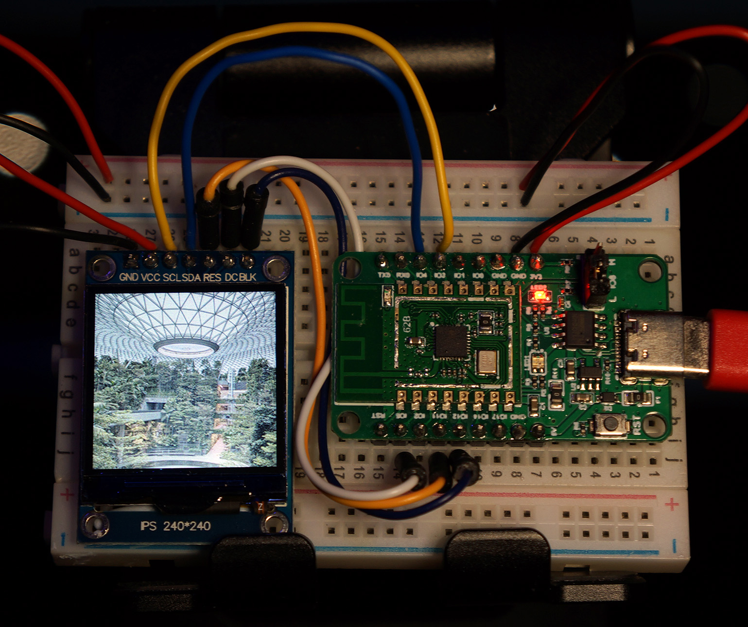
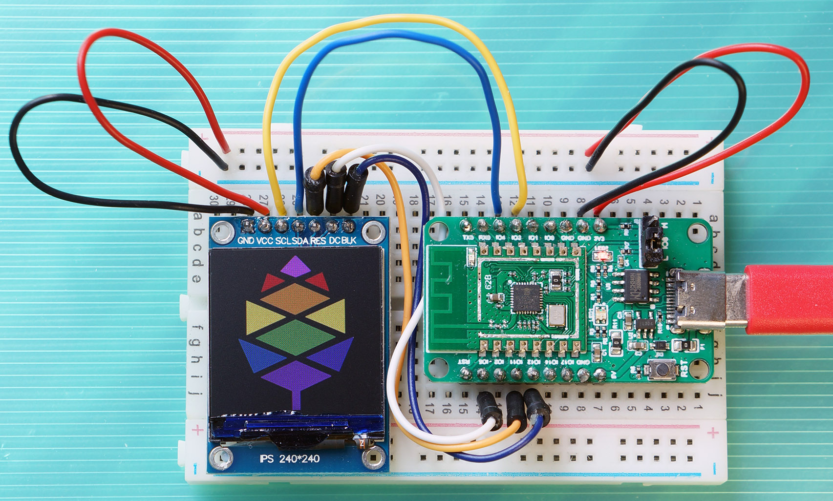
PineCone BL602 rendering on ST7789 a photo of Jewel Changi, Singapore
Our First Act: BL602 renders an image to our ST7789 Display! (Based on this photo)
Prologue: We prepare a buffer for transmitting pixels to ST7789: display.c
/// SPI Transmit Buffer. We always copy pixels from Flash ROM to RAM
/// before transmitting, because Flash ROM may be too slow for DMA at 4 MHz.
/// Contains 10 rows of 240 pixels of 2 bytes each (16-bit colour).
uint8_t spi_tx_buf[
    BUFFER_ROWS        //  10 rows of pixels
    * COL_COUNT        //  240 columns of pixels per row
    * BYTES_PER_PIXEL  //  2 bytes per pixel
];
The SPI Transmit Buffer spi_tx_buf is the same size as our SPI Receive Buffer spi_rx_buf.
Both buffers are sized to store 10 rows of pixels, each row with 240 pixels, each pixel with 2 colour bytes (16-bit colour).
(Our display has 240 rows of pixels, so we’ll use our buffers 24 times to render an image)
We shall blast 10 rows of pixels to ST7789, and do it 24 times: display.c
/// Display image on ST7789 display controller
int display_image(void) {
// Render each batch of 10 rows. ROW_COUNT is 240, BUFFER_ROWS is 10.
for (uint8_t row = 0; row < ROW_COUNT; row += BUFFER_ROWS) {
// Compute the (left, top) and (right, bottom)
// coordinates of the 10-row window
uint8_t top = row;
uint8_t bottom = (row + BUFFER_ROWS - 1) < ROW_COUNT
? (row + BUFFER_ROWS - 1)
: (ROW_COUNT - 1);
uint8_t left = 0;
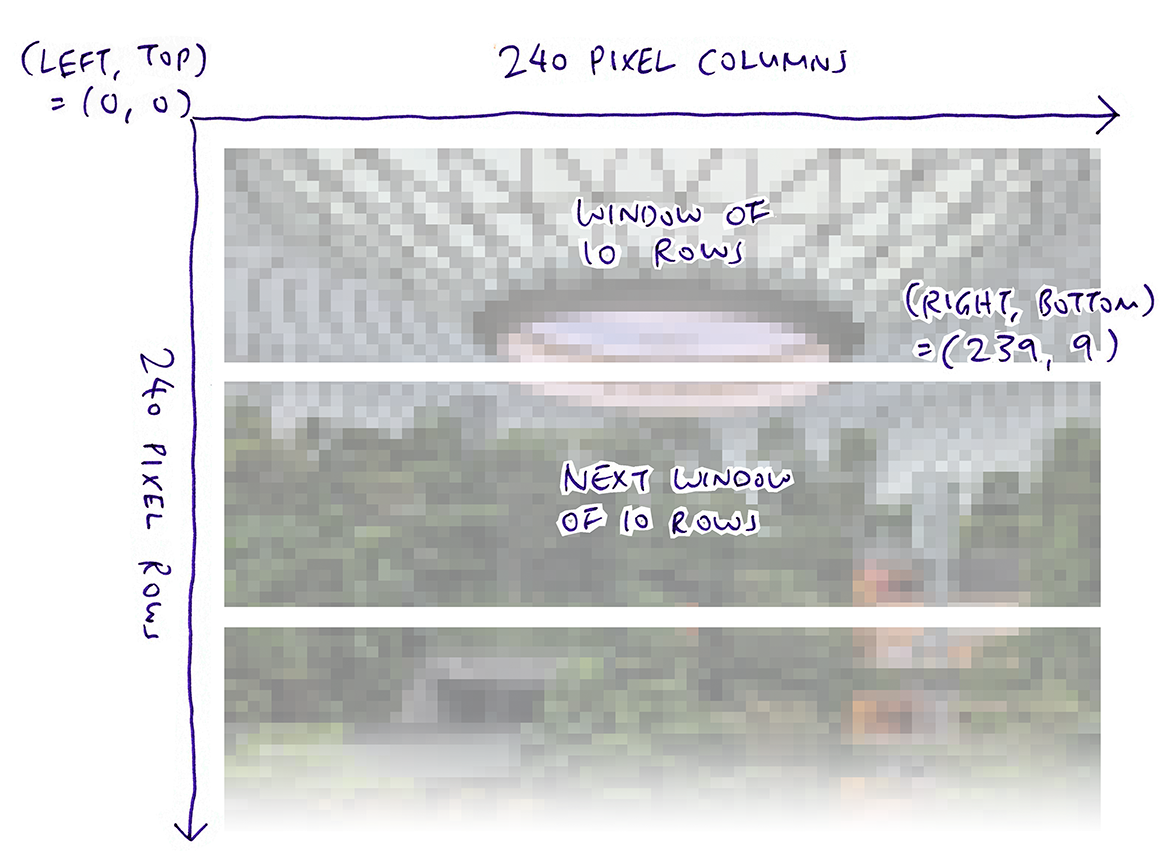
uint8_t right = COL_COUNT - 1; // COL_COUNT is 240What are left, right, top and bottom?
Before we blast a batch of 10 pixel rows to ST7789 over SPI, we tell ST7789 the (left, top) and (right, bottom) coordinates of the Display Window for the pixel rows.
The code above computes the coordinates of the Display Window like so…
Next we compute the byte offset of our image in Flash ROM, and the number of bytes to blast…
        //  Compute the offset and how many bytes we will transmit.
        //  COL_COUNT is 240, BYTES_PER_PIXEL is 2.
        uint32_t offset = ((top * COL_COUNT) + left)
            * BYTES_PER_PIXEL;
        uint16_t len    = (bottom - top + 1)
            * (right - left + 1)
            * BYTES_PER_PIXEL;
We copy 10 rows of pixel data from our image in Flash ROM to the SPI Transmit Buffer…
        //  Copy the image pixels from Flash ROM to RAM, because Flash ROM may be too slow for DMA at 4 MHz
        memcpy(spi_tx_buf, image_data + offset, len);
(What’s image_data? Why don’t we transmit the data straight from Flash ROM? We’ll explain in a while)
Here’s another… ST7789 Command! This sets the coordinates of the ST7789 Display Window…
        //  Set the display window.
        int rc = set_window(left, top, right, bottom); assert(rc == 0);
(We’ll see set_window in a while)
Finally one last ST7789 Command (Memory Write) to blast the pixel data from our SPI Transmit Buffer to the ST7789 Display…
        //  Memory Write: Write the bytes from RAM to display (ST7789 Datasheet Page 202)
        rc = write_command(RAMWR, NULL, 0); assert(rc == 0);
        rc = write_data(spi_tx_buf, len);   assert(rc == 0);
    }
    return 0;
}
We repeat this 24 times to render each Display Window of 10 pixel rows… And Jewel Changi, Singapore magically appears on our ST7789 Display!
Jewel Changi, Singapore looks truly awesome… But can we show a cat photo instead?
Absolutely! The photo is rendered from this image_data array that’s compiled into BL602’s Flash ROM: display.c
/// RGB565 Image. Converted by https://github.com/lupyuen/pinetime-graphic
/// from PNG file https://github.com/lupyuen/pinetime-logo-loader/blob/master/logos/pine64-rainbow.png
static const uint8_t image_data[] = {  //  Should be 115,200 bytes
#include "image.inc"
};
Here we see that image_data includes this file that contains 115,200 bytes of pixel data: image.inc
0xa5, 0x35, 0x6b, 0x4d, 0x42, 0x49, 0x74, 0x10, 0xb5, 0xd7, 0x4a, 0x29, 0x83, 0xcf, 0xef, 0x9d,
0xdf, 0x1b, 0x8c, 0x52, 0x31, 0x45, 0x4a, 0x28, 0x73, 0x8e, 0xad, 0x95, 0xad, 0x96, 0x7c, 0x10,
0x7c, 0x11, 0xd6, 0xfb, 0xf7, 0xde, 0xd6, 0xfb, 0xe7, 0x7d, 0xb5, 0x97, 0x42, 0x09, 0x9c, 0xf3,
...
(That’s 240 pixel rows * 240 pixel columns * 2 bytes per pixel)
To create our own image.inc, prepare a 240 x 240 PNG file named image.png. Then do this…
## Download the pinetime-graphic source code
git clone https://github.com/lupyuen/pinetime-graphic
cd pinetime-graphic

## TODO: Copy image.png to the pinetime-graphic folder

## Convert the PNG file to a C array
cargo run -v image.png >image.inc
(Check out the pinetime-graphic source code here)
Before we blast pixels to ST7789, here’s how set_window sets the ST7789 Display Window, bounded by the coordinates (left, top) and (right, bottom): display.c
/// Set the ST7789 display window to the coordinates (left, top), (right, bottom)
int set_window(uint8_t left, uint8_t top, uint8_t right, uint8_t bottom) {
    //  Set Address Window Columns (ST7789 Datasheet Page 198)
    int rc = write_command(CASET, NULL, 0); assert(rc == 0);
    uint8_t col_para[4] = { 0x00, left, 0x00, right };
    rc = write_data(col_para, 4); assert(rc == 0);
set_window first sends the ST7789 Command to set the Address Window Columns. That’s followed by the left and right values.
    //  Set Address Window Rows (ST7789 Datasheet Page 200)
    rc = write_command(RASET, NULL, 0); assert(rc == 0);
    uint8_t row_para[4] = { 0x00, top, 0x00, bottom };
    rc = write_data(row_para, 4); assert(rc == 0);
    return 0;
}
Then set_window sends the ST7789 Command to set the Address Window Rows, followed by the top and bottom values.
ST7789 demo firmware for BL602
Let’s run the ST7789 Demo Firmware for BL602.
Download the Firmware Binary File sdk_app_st7789.bin from…
Alternatively, we may build the Firmware Binary File sdk_app_st7789.bin from the source code…
## Download the master branch of lupyuen's bl_iot_sdk
git clone --recursive --branch master https://github.com/lupyuen/bl_iot_sdk
cd bl_iot_sdk/customer_app/sdk_app_st7789

## TODO: Replace sdk_app_st7789/image.inc
## by Our Favourite Cat. See https://lupyuen.github.io/articles/display#modding-the-photo

## TODO: Change this to the full path of bl_iot_sdk
export BL60X_SDK_PATH=$HOME/bl_iot_sdk
export CONFIG_CHIP_NAME=BL602
make

## For WSL: Copy the firmware to /mnt/c/blflash, which refers to c:\blflash in Windows
mkdir /mnt/c/blflash
cp build_out/sdk_app_st7789.bin /mnt/c/blflash
More details on building bl_iot_sdk
Follow these steps to install blflash…
We assume that our Firmware Binary File sdk_app_st7789.bin has been copied to the blflash folder.
Set BL602 to Flashing Mode and restart the board…
For PineCone:
Set the PineCone Jumper (IO 8) to the H Position (Like this)
Press the Reset Button
For BL10:
Connect BL10 to the USB port
Press and hold the D8 Button (GPIO 8)
Press and release the EN Button (Reset)
Release the D8 Button
For Ai-Thinker Ai-WB2, Pinenut and MagicHome BL602:
Disconnect the board from the USB Port
Connect GPIO 8 to 3.3V
Reconnect the board to the USB port
Enter these commands to flash sdk_app_st7789.bin to BL602 over UART…
## For Linux:
blflash flash build_out/sdk_app_st7789.bin \
    --port /dev/ttyUSB0

## For macOS:
blflash flash build_out/sdk_app_st7789.bin \
    --port /dev/tty.usbserial-1420 \
    --initial-baud-rate 230400 \
    --baud-rate 230400

## For Windows: Change COM5 to the BL602 Serial Port
blflash flash c:\blflash\sdk_app_st7789.bin --port COM5
(For WSL: Do this under plain old Windows CMD, not WSL, because blflash needs to access the COM port)
More details on flashing firmware
Set BL602 to Normal Mode (Non-Flashing) and restart the board…
For PineCone:
Set the PineCone Jumper (IO 8) to the L Position (Like this)
Press the Reset Button
For BL10:
For Ai-Thinker Ai-WB2, Pinenut and MagicHome BL602:
Disconnect the board from the USB Port
Connect GPIO 8 to GND
Reconnect the board to the USB port
After restarting, connect to BL602’s UART Port at 2 Mbps like so…
For Linux:
screen /dev/ttyUSB0 2000000For macOS: Use CoolTerm (See this)
For Windows: Use putty (See this)
Alternatively: Use the Web Serial Terminal (See this)
More details on connecting to BL602
Let’s enter some commands to display an image!
Press Enter to reveal the command prompt.
Enter help to see the available commands…
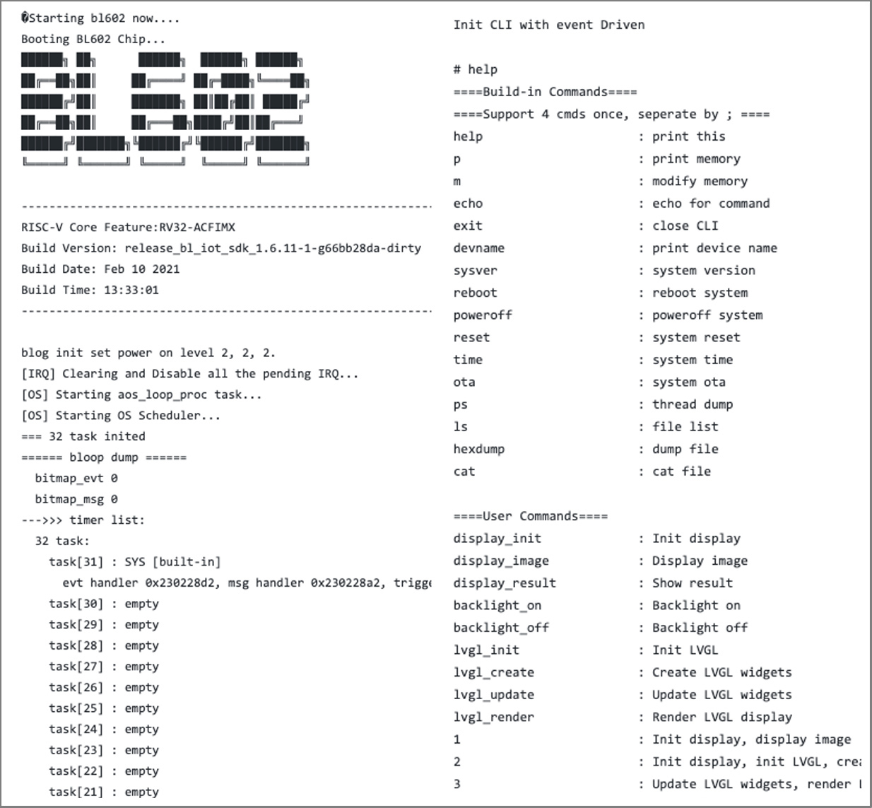
help
====User Commands====
display_init             : Init display
display_image            : Display image
display_result           : Show result
backlight_on             : Backlight on
backlight_off            : Backlight off
We’ll cover the LVGL commands later…
lvgl_init                : Init LVGL
lvgl_create              : Create LVGL widgets
lvgl_update              : Update LVGL widgets
lvgl_render              : Render LVGL display
And these shortcuts too…
1                        : Init display, display image
2                        : Init display, init LVGL, create LVGL widgets, render LVGL display
3                        : Update LVGL widgets, render LVGL display
First we initialise our SPI Port and ST7789 Display.
Enter this command…
display_initThis command calls the functions test_display_init and init_display, which we have seen earlier.
We should see this…
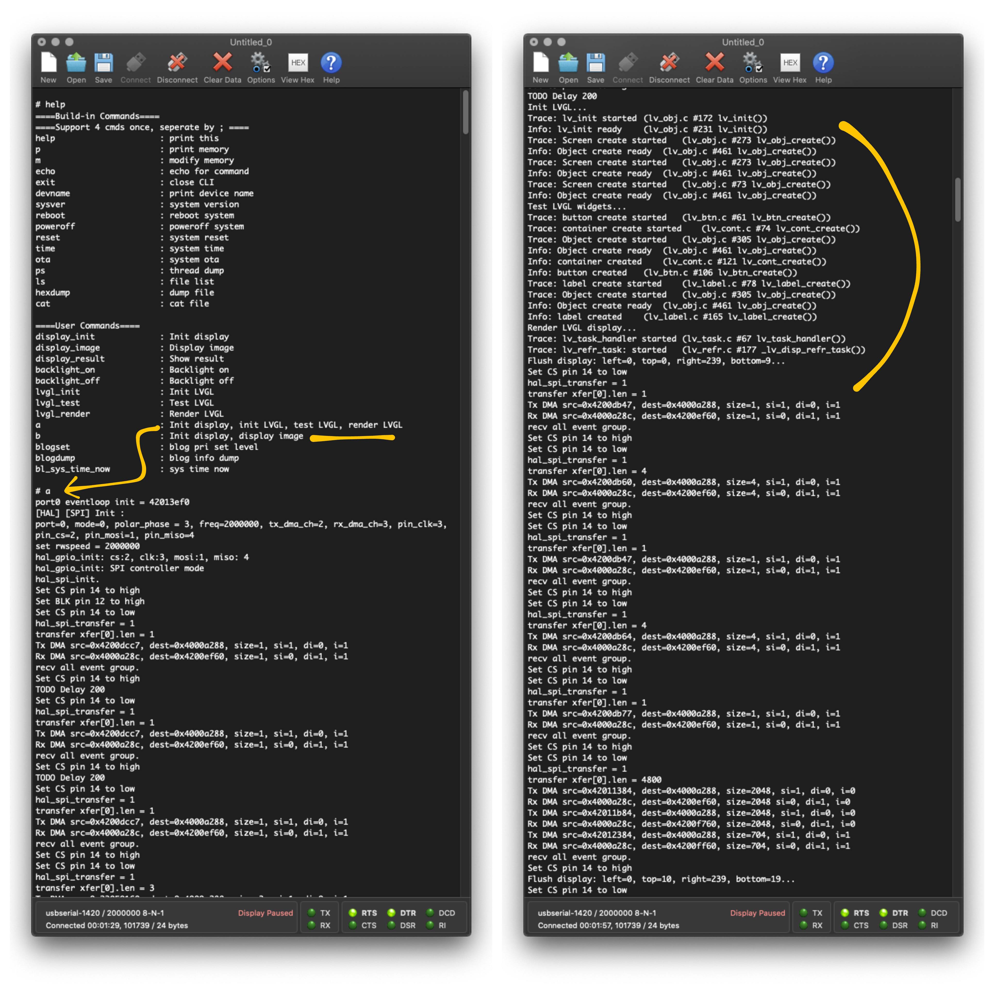
display_init
port0 eventloop init = 42013ef8
[HAL] [SPI] Init :
port=0, mode=0, polar_phase = 3, freq=4000000, tx_dma_ch=2, rx_dma_ch=3, pin_clk=3, pin_cs=2, pin_mosi=1, pin_miso=4
set rwspeed = 4000000
The above messages say that our SPI Port has been configured by the BL602 SPI HAL.
hal_gpio_init: cs:2, clk:3, mosi:1, miso: 4
hal_gpio_init: SPI controller mode
hal_spi_init.
Set CS pin 14 to high
Set BLK pin 12 to high
init_display has just configured the GPIO Pins and switched on the backlight.
Set CS pin 14 to low
hal_spi_transfer = 1
transfer xfer[0].len = 1
Tx DMA src=0x4200dcdf, dest=0x4000a288, size=1, si=1, di=0, i=1
Rx DMA src=0x4000a28c, dest=0x4200ef68, size=1, si=0, di=1, i=1
recv all event group.
Set CS pin 14 to high
TODO Delay 200
...
Followed by the eight ST7789 Init Commands sent by init_display.
Next we display the image on ST7789…
display_imageThis command calls the function display_image, which we have seen earlier.
We should see this…
display_image
Displaying image...
Set CS pin 14 to low
hal_spi_transfer = 1
transfer xfer[0].len = 4800
Tx DMA src=0x42012858, dest=0x4000a288, size=2048, si=1, di=0, i=0
Rx DMA src=0x4000a28c, dest=0x4200ef68, size=2048, si=0, di=1, i=0
Tx DMA src=0x42013058, dest=0x4000a288, size=2048, si=1, di=0, i=0
Rx DMA src=0x4000a28c, dest=0x4200f768, size=2048, si=0, di=1, i=0
Tx DMA src=0x42013858, dest=0x4000a288, size=704,  si=1, di=0, i=1
Rx DMA src=0x4000a28c, dest=0x4200ff68, size=704,  si=0, di=1, i=1
...
That’s display_image blasting the ST7789 Commands to set the Display Window, then blasting the pixel data for 10 rows.
This repeats 24 times until the entire image is rendered.
Why so many SPI DMA Transfers?
Each SPI DMA Transfer is limited to 2,048 bytes.
Whenever we transmit our SPI Buffer of 4,800 bytes (10 rows of pixels), BL602 SPI HAL helpfully breaks down the request into multiple SPI DMA requests (of max 2,048 bytes each).
Here’s a Tip: Instead of entering the two commands…
display_init
...
display_image
We may enter this as a shortcut…
1Which will initialise the ST7789 display and render the image in a single command.
Congratulations! Jewel Changi, Singapore (or Our Favourite Cat) now appears on our ST7789 Display!
PineCone BL602 rendering on ST7789 a photo of Jewel Changi, Singapore
Rendering photos on BL602 and ST7789 is great… But is it useful for creating IoT Gadgets?
Not really, we’ll need to render text and shapes to show meaningful information. (Like a mini-dashboard)
Is there a way to render text and graphics on BL602 + ST7789… Similar to mobile apps?
Yes there’s a way… We call the open-source LVGL Graphics Library!
Watch how we render this simple screen with LVGL: A Button and a Text Label…
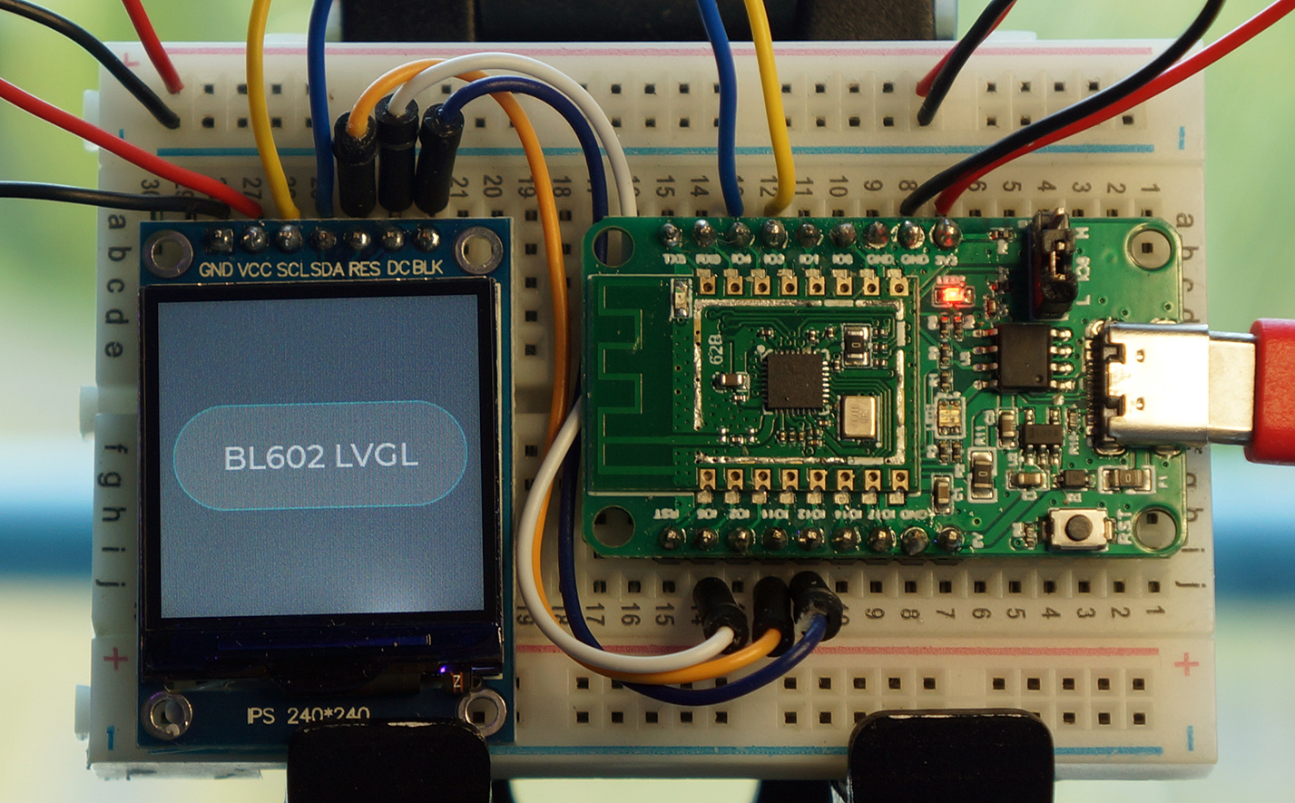
Button and label rendered with LVGL
First we declare the LVGL Widgets (user interface controls) for our button and our label…
/// Button Widget
static lv_obj_t *btn = NULL;

/// Label Widget
static lv_obj_t *label = NULL;
We create the button and set its position and size like so: lvgl.c
/// Create a Button Widget and a Label Widget
int lvgl_create(void) {
    ...
    //  Add a button the current screen
    btn = lv_btn_create(lv_scr_act(), NULL);

    //  Set its position (left = 10, top = 80)
    lv_obj_set_pos(btn, 10, 80);

    //  Set its size (width = 220, height = 80)
    lv_obj_set_size(btn, 220, 80);
Next we create the label for the button and set the text…
    //  Add a label to the button
    label = lv_label_create(btn, NULL);

    //  Set the label text
    lv_label_set_text(label, "BL602 LVGL");
    return 0;
}
And that’s how we create a button and a label in our function lvgl_create!
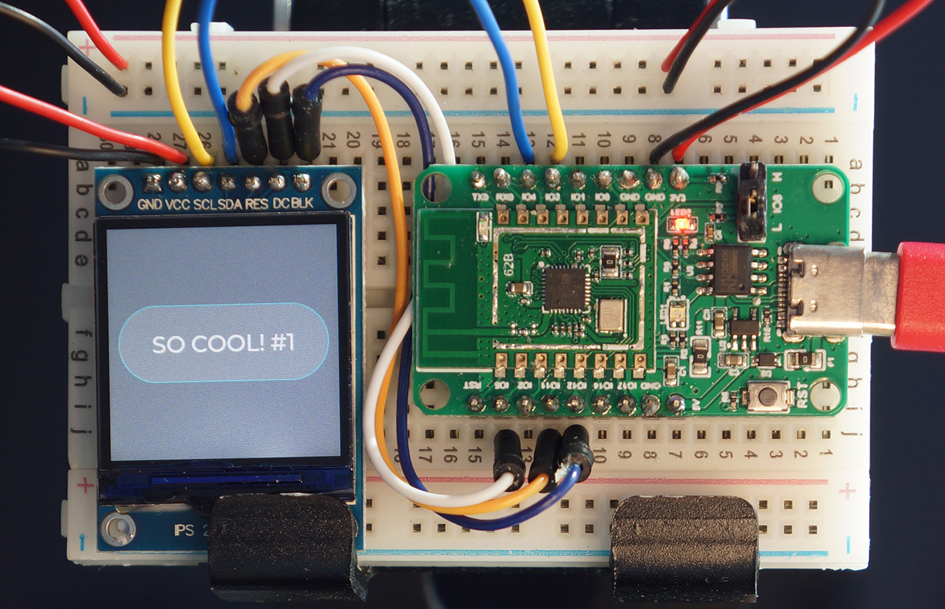
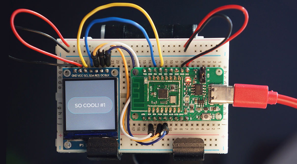
Updated LVGL label
Static screens don’t look terribly exciting on IoT Gadgets… Let’s make our screens dynamic! (Like the pic above)
Here’s our function lvgl_update that will change the label text every time it’s called: lvgl.c
/// Update the Widgets
int lvgl_update(void) {
    ...
    //  Compose a message that changes every time we're called
    static int counter = 1;
    char msg[20];
    snprintf(msg, sizeof(msg), "SO COOL! #%d", counter++);
First we compose a dynamic message…
SO COOL! #1…That changes (the number at the end) every time the function is called.
Then we set the label text to the new message…
    //  Set the button label to the new message
    lv_label_set_text(label, msg);
    return 0;
}
LVGL makes it really easy to create dynamic screens for IoT Gadgets… Even for RISC-V BL602!
LVGL was designed for interactive displays (like touchscreens).
It refreshes the display efficiently without consuming too much CPU and RAM. (Which are scarce on IoT Gadgets)
Here’s how we tell LVGL to render the screen that we have created (or updated): lvgl.c
/// Render the LVGL display
int lvgl_render(void) {
    ...
    //  Must tick at least 100 milliseconds to force LVGL to render display
    lv_tick_inc(100);

    //  Call LVGL to render the display and flush our display driver
    lv_task_handler();
    return 0;
}
The rendering code in lvgl_render looks unusual… But that’s because we’re pretending to be an interactive gadget.
(This code should make sense once we start building interactive gadgets with BL602)
(One last thing before the demo…)
Here’s how we initialise the LVGL Library: lvgl.c
/// Set to true if LVGL has already been lvgl_initialised
static bool lvgl_initialised = false;

/// Init the LVGL library
int lvgl_init(void) {
    //  Assume that display controller has been initialised
    if (lvgl_initialised) { return 0; }  //  Init only once
    lvgl_initialised = true;

    //  Init the LVGL display
    lv_init();
    lv_port_disp_init();
    return 0;
}
Check out the LVGL docs…
LVGL demo firmware running on CoolTerm
Now we run the LVGL Demo Firmware for BL602… Which happens to be the same ST7789 Demo Firmware that we’ve run earlier: sdk_app_st7789.bin
Follow these steps…
Flash the sdk_app_st7789.bin firmware to our BL602 Board
Set BL602 to Normal Mode (Non-Flashing) and restart the board…
For PineCone:
Set the PineCone Jumper (IO 8) to the L Position (Like this)
Press the Reset Button
For BL10:
For Ai-Thinker Ai-WB2, Pinenut and MagicHome BL602:
Disconnect the board from the USB Port
Connect GPIO 8 to GND
Reconnect the board to the USB port
Connect to BL602’s UART Port at 2 Mbps like so…
For Linux:
screen /dev/ttyUSB0 2000000For macOS: Use CoolTerm (See this)
For Windows: Use putty (See this)
Alternatively: Use the Web Serial Terminal (See this)
Now we enter the commands to initialise the SPI Port, ST7789 Display and LVGL Library…
Press Enter to reveal the command prompt.
Enter help to see the available commands…
help
====User Commands====
display_init             : Init display
display_image            : Display image
display_result           : Show result
backlight_on             : Backlight on
backlight_off            : Backlight off
We’ll run these LVGL commands in a while…
lvgl_init                : Init LVGL
lvgl_create              : Create LVGL widgets
lvgl_update              : Update LVGL widgets
lvgl_render              : Render LVGL display
And these shortcuts too…
1                        : Init display, display image
2                        : Init display, init LVGL, create LVGL widgets, render LVGL display
3                        : Update LVGL widgets, render LVGL display
Enter this command to initialise the SPI Port and ST7789 Display…
display_initThis command calls the functions test_display_init and init_display, which we have seen earlier.
(We’ve covered this command earlier under ST7789 Demo Firmware)
Enter this command to initialise the LVGL Library
lvgl_initThis command calls the function lvgl_init, which we have seen earlier.
We should see this…
Init LVGL...
Trace: lv_init started 	     (lv_obj.c #172 lv_init())
Info:  lv_init ready 	     (lv_obj.c #231 lv_init())
Trace: Screen create started (lv_obj.c #273 lv_obj_create())
Info:  Object create ready 	 (lv_obj.c #461 lv_obj_create())
The above messages say that the LVGL Library has initialised the screen.
We’re all set to create some LVGL Widgets!
Enter this command to create the LVGL Widgets (Button and Label)…
lvgl_createThis command calls the function lvgl_create, which we have seen earlier.
We should see this…
Create LVGL widgets...
Trace: button create started 	(lv_btn.c #61 lv_btn_create())
Trace: container create started (lv_cont.c #74 lv_cont_create())
Trace: Object create started 	(lv_obj.c #305 lv_obj_create())
Info:  Object create ready 	    (lv_obj.c #461 lv_obj_create())
Info:  container created 	    (lv_cont.c #121 lv_cont_create())
Info:  button created 	        (lv_btn.c #106 lv_btn_create())
LVGL has created the Button Widget and its Widget Container.
(Because our Button Widget will contain a Label Widget)
Trace: label create started 	(lv_label.c #78 lv_label_create())
Trace: Object create started 	(lv_obj.c #305 lv_obj_create())
Info:  Object create ready 	    (lv_obj.c #461 lv_obj_create())
Info:  label created 	        (lv_label.c #165 lv_label_create())
Then LVGL creates the Label Widget and assigns it to the Button Widget.
Enter this command to render the LVGL Screen…
lvgl_renderThis command calls the function lvgl_render, which we have seen earlier.
We should see this…
Render LVGL display...
Trace: lv_task_handler started 	(lv_task.c #67 lv_task_handler())
Trace: lv_refr_task: started 	(lv_refr.c #177 _lv_disp_refr_task())
Remember that we’re pretending to be an interactive gadget… And we’re calling the LVGL Task Handler to refresh our screen.
Then we see this…
Flush display: left=0, top=0, right=239, bottom=9...Here our ST7789 Display Driver for LVGL renders the first 10 rows of the LVGL screen.
(Guess where it goes?)
transfer xfer[0].len = 4800
Tx DMA src=0x42012858, dest=0x4000a288, size=2048, si=1, di=0, i=0
Rx DMA src=0x4000a28c, dest=0x4200ef68, size=2048, si=0, di=1, i=0
...
Yep our ST7789 Driver calls write_data and transmit_spi to blast the 10 pixel rows to ST7789 over SPI DMA…
The same way that we render Jewel Changi, Singapore and Our Favourite Feline!
Our ST7789 Driver blasts the next Display Window of 10 pixel rows…
Flush display: left=0, top=10, right=239, bottom=19...
...
Flush display: left=0, top=20, right=239, bottom=29...
...
Flush display: left=0, top=30, right=239, bottom=39...
...
Flush display: left=0, top=40, right=239, bottom=49...
...
We do this 24 times to render the entire LVGL Screen.
LVGL is super efficient in using RAM. It doesn’t need an entire 240 x 240 Screen Buffer in RAM… Only 10 rows of 240 pixel columns will do!
Finally we see our LVGL Screen (Button and Label) rendered on the ST7789 Display…
Button and label rendered by LVGL on Sunday morning
Enter this command to update the LVGL Widgets…
lvgl_updateThis command calls the function lvgl_update, which we have seen earlier.
Remember that lvgl_update updates the label text to…
SO COOL! #1Then this command to render the updated LVGL Screen…
lvgl_render(We’ve used this command in the previous section)
This time LVGL renders our updated screen a little differently…
Flush display: left=45, top=107, right=196, bottom=121...
...
Flush display: left=45, top=122, right=196, bottom=133...
...
Instead of re-rendering all 240 pixel rows, LVGL renders only the pixel rows that have changed!
(Very clever!)
That’s why LVGL is perfect for RISC-V IoT Gadgets that have CPU and RAM constraints.
Here are two Shortcuts: This Shortcut Command…
2Is equivalent to…
display_init
lvgl_init
lvgl_create
lvgl_render
And this Shortcut Command…
3Is equivalent to…
lvgl_update
lvgl_render
Watch the Demo Video on YouTube
Updated LVGL label
Let’s find out how the ST7789 Display Driver for LVGL calls write_data and transmit_spi to blast pixels over SPI DMA.
Here are the ST7789 Specifications for LVGL: lv_conf.h
/// Number of rows in SPI Transmit and Receive Buffers.
/// Used by display.c and lv_port_disp.c
#define BUFFER_ROWS       (10)

/// Horizontal and vertical resolution
#define LV_HOR_RES_MAX    (240)
#define LV_VER_RES_MAX    (240)

/// Color depth: 16 (RGB565)
#define LV_COLOR_DEPTH     16

/// Swap the 2 bytes of RGB565 color
#define LV_COLOR_16_SWAP   1
Note that LVGL is buffering 10 pixel rows of data in RAM.
(It’s the same buffer we used for rendering photos: spi_tx_buf)
This function disp_flush is called by LVGL to blast a Display Window of pixels from RAM to the ST7789 Display: lv_port_disp.c
/// ST7789 Command for Memory Write. From https://github.com/almindor/st7789/blob/master/src/instruction.rs
#define RAMWR 0x2C

static void disp_flush(
    lv_disp_drv_t *disp_drv,  //  LVGL Display Driver
    const lv_area_t *area,    //  Display Window Coordinates
    lv_color_t * color_p      //  Pixel data (RGB565)
) {
    //  Set the ST7789 display window coordinates to (Left, Top), (Right, Bottom)
    int rc = set_window(
        area->x1,  //  Left
        area->y1,  //  Top
        area->x2,  //  Right
        area->y2   //  Bottom
    ); assert(rc == 0);
Here we set the ST7789 Display Window, calling the set_window function that we’ve defined earlier.
    //  How many pixels we'll be rendering
    int len =
        ((area->x2 - area->x1) + 1) *  //  Width
        ((area->y2 - area->y1) + 1) *  //  Height
        2;                             //  2 bytes per pixel

    //  Memory Write: Write the bytes to display (ST7789 Datasheet Page 202)
    rc = write_command(RAMWR, NULL, 0); assert(rc == 0);
    rc = write_data((const uint8_t *) color_p, len); assert(rc == 0);
Next we call write_command and write_data to blast the pixel data to ST7789.
As we have seen, write_data calls BL602 SPI HAL to blast the data to our SPI Port, accelerated by DMA.
    //  Inform LVGL that we are done with the flushing
    lv_disp_flush_ready(disp_drv);
}
By convention, we call the LVGL function lv_disp_flush_ready when we’re done.
And that’s how disp_flush blasts a Display Window of pixels from RAM to the ST7789 Display over SPI DMA!
How does LVGL call disp_flush?
When we register our ST7789 Display Driver with LVGL, we set disp_flush as the Callback Function for rendering a Display Window of pixels.
Here’s how we register our ST7789 Display Driver with LVGL: lv_port_disp.c
void lv_port_disp_init(void) {
    //  Initialize our display
    disp_init();

    //  Create a buffer for drawing: LVGL requires a buffer where
    //  it draws the objects. The buffer has to be greater than 1
    //  display row.  We create one buffer spi_tx_buf with 10 rows.
    //  LVGL will draw the display's content here and write it to the display
    static lv_disp_buf_t disp_buf_1;
    lv_disp_buf_init(
        &disp_buf_1,
        spi_tx_buf,
        NULL,
        LV_HOR_RES_MAX * BUFFER_ROWS
    );
Here in lv_port_disp_init we set spi_tx_buf as the buffer for 10 rows of pixels.
Recall that spi_tx_buf is the SPI Transmit Buffer we used for rendering the photo on ST7789.
    //  Init the display driver
    lv_disp_drv_t disp_drv;        //  Descriptor of a display driver
    lv_disp_drv_init(&disp_drv);   //  Basic initialization

    //  Set the resolution of the display
    disp_drv.hor_res = LV_HOR_RES_MAX;
    disp_drv.ver_res = LV_VER_RES_MAX;

    //  Set the callback for copying the buffer's content to the display
    disp_drv.flush_cb = disp_flush;
In the code above we initialise the ST7789 Display Driver and set the Callback Function to disp_flush.
    //  Set the buffer for the display driver
    disp_drv.buffer = &disp_buf_1;

    //  Register the display driver
    lv_disp_drv_register(&disp_drv);
}
Finally we register the ST7789 Display Driver with LVGL. We have just configured LVGL to…
Use spi_tx_buf as the rendering buffer in RAM
(Containing 10 rows of pixels)
Call disp_flush to blast the pixels from spi_tx_buf to ST7789 over SPI DMA
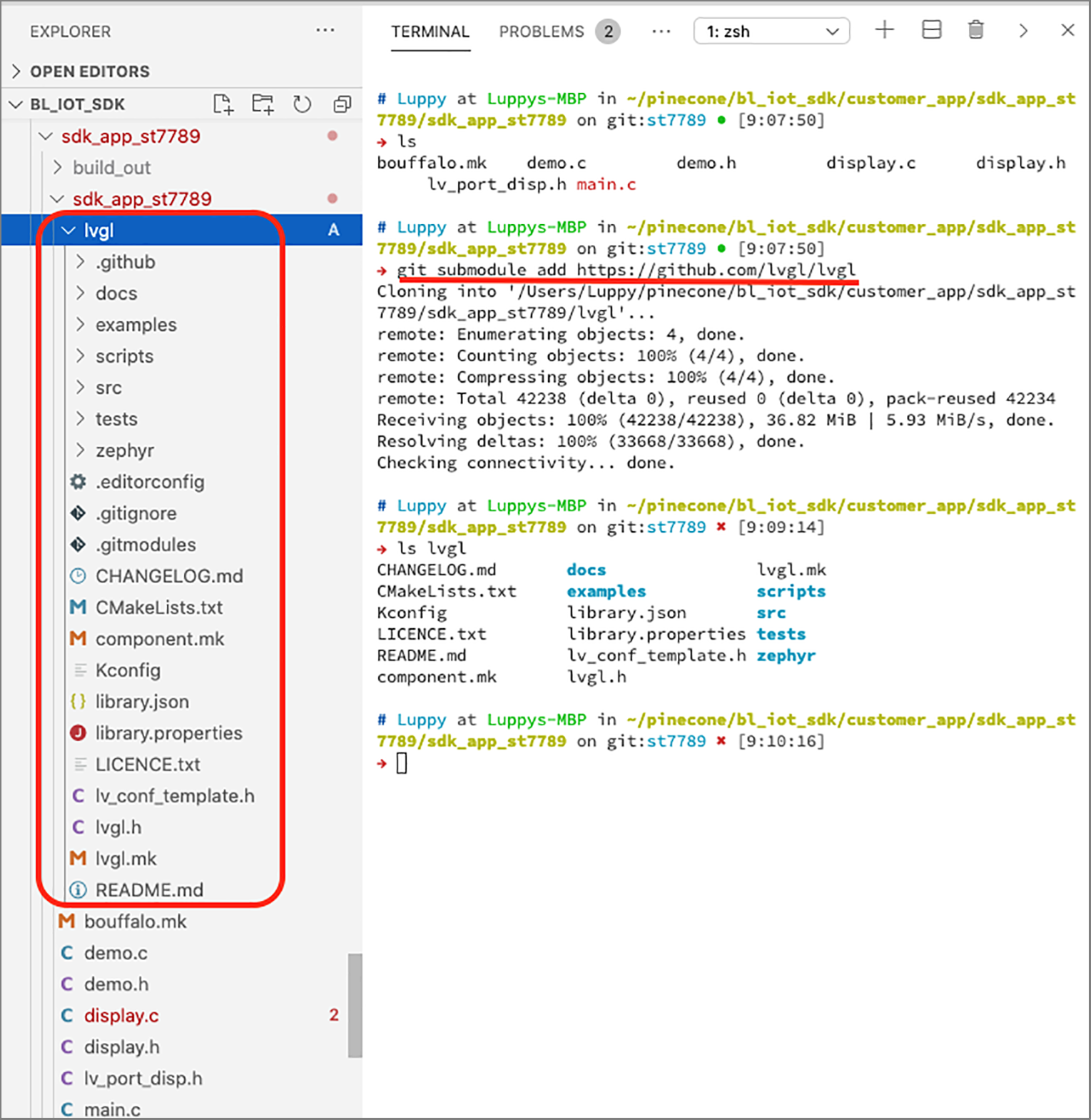
LVGL source code in BL602 demo firmware
How did we add the LVGL Source Code to the BL602 Firmware?
Not so elegantly, I’m afraid. (See pic above)
The LVGL Library lives in a strange place, inside the lvgl folder under sdk_app_st7789…
#  How we added LVGL Library under sdk_app_st7789
cd bl_iot_sdk/customer_app/sdk_app_st7789/sdk_app_st7789
git submodule add https://github.com/lvgl/lvgl
Why is this a strange place?
Because the BL602 SDK Makefile doesn’t recognise subfolders under sdk_app_st7789.
Here’s the hack we added to a Common Makefile to support LVGL: make_scripts_riscv/ component_wrapper.mk
# TODO: Add LVGL to build in a cleaner way
COMPONENT_SRCDIRS += \
	./lvgl/src/lv_core \
	./lvgl/src/lv_draw \
	./lvgl/src/lv_font \
	./lvgl/src/lv_gpu  \
	./lvgl/src/lv_hal  \
	./lvgl/src/lv_misc   \
	./lvgl/src/lv_themes \
	./lvgl/src/lv_widgets
Hopefully someday we shall create a proper BL602 Library for LVGL…
The GitHub Actions Workflow was updated to do Recursive Checkout to populate the LVGL folder. (See this)
Check the Appendix for the LVGL Configuration
Some people might say that blasting pixels at 4 Mbps is rather slow… Can we do faster?
BL602 SPI is technically rated for 40 MHz (or 40 Mbps). But during our testing, the SPI DMA Transfer to ST7789 tends to hang at speeds beyond 4 Mbps.
(Why does it hang instead of crashing with an exception? Because the BL602 SPI HAL doesn’t set the SPI Timeout. We’ll explain this shortly)
Here are some possible causes for SPI DMA Transfers failing beyond 4 Mbps…
We’re using a Breadboard to connect BL602 and ST7789, and the Electrical Connection may limit the speed. As suggested by TL (Pine64 Boss)
(Sorry… But I love Colourful Curvy Cables!)
Perhaps this problem will be fixed when we create a proper Printed Circuit Board for BL602 and ST7789.
We’re calling the BL602 SPI HAL to Transmit AND Receive SPI data… But we’re not supposed to receive any SPI data from ST7789.
(Perhaps BL602 is stuck waiting for ST7789 to return data over SPI)
To test this, we would need to hack the BL602 SPI HAL and disable SPI Receive.
(Here’s where we should hack: lli_list_init and hal_spi_dma_trans)
When I was blasting the photo directly from BL602 Flash ROM to ST7789, I had to lower the speed to 2 Mbps to avoid hanging.
That’s why we copy the photo to RAM before blasting to ST7789 at 4 Mbps.
Lesson Learnt: Don’t blast pixels from Flash ROM to ST7789… Somehow DMA works slower for Flash ROM.
Could there be some other DMA limitation that’s failing the SPI Transfer beyond 4 Mbps?
How do we set an SPI Timeout for easier troubleshooting… So that it doesn’t hang?
Here’s how we modify the BL602 SPI HAL to set the SPI Timeout to 100 milliseconds: components/hal_drv/ bl602_hal/hal_spi.c
static void hal_spi_dma_trans(...) {
    ...
    //  Wait for for the FreeRTOS Event Group,
    //  which is signalled by the SPI DMA Transmit and
    //  Receive Interrupt Handlers when the transfer completes.
    uxBits = xEventGroupWaitBits(   //  Wait for...
        arg->spi_dma_event_group,   //  Event Group
        EVT_GROUP_SPI_DMA_TR,       //  For BOTH Transmit and Receive to complete
        pdTRUE,                     //  Clear bits on exit
        pdTRUE,                     //  Both Transmit and Receive bits must be set
        //  Set SPI Timeout to 100 milliseconds.
        //  Previously portMAX_DELAY (no timeout).
        100 / portTICK_PERIOD_MS
    );
Then enter the display_result command to dump the Interrupt Counters and Error Codes. (See this)
Remember to enable Assertion Failure messages in our firmware. (See this)
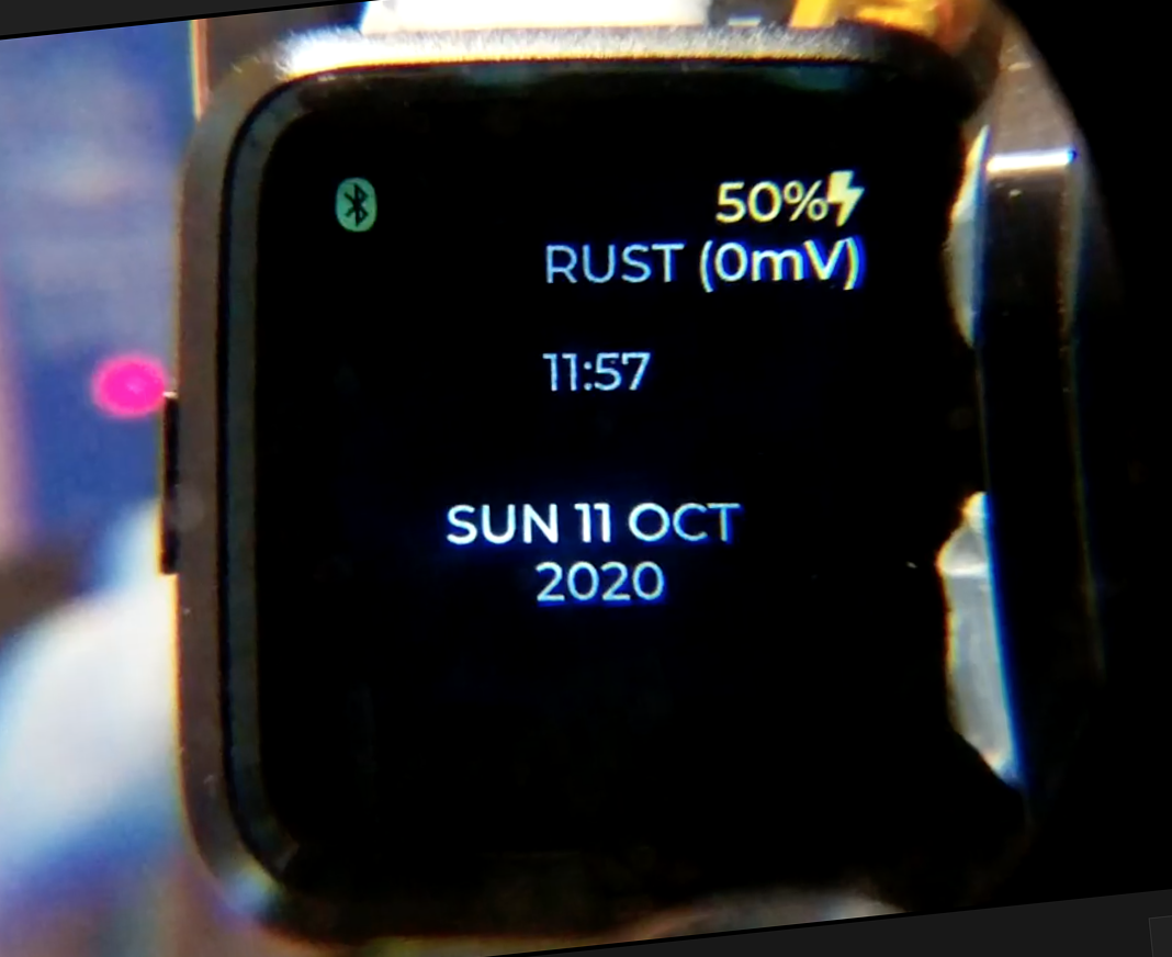
Watch face for PineTime Smartwatch rendered with LVGL
The ST7789 and LVGL code for BL602 runs on FreeRTOS today. Will the code run on other Embedded Operating Systems? Like Mynewt, RIOT, Rust, Zephyr, …
Yes! Like an episode of WandaVision, this article has dropped many hints about its Origin Story…
The code in this article came from PineTime Smartwatch!
And the reused source files: display.c, lvgl.c, lv_conf.h, lv_port_disp.c
On PineTime this ST7789 + LVGL code (or a highly similar variant) worked OK on FreeRTOS, Mynewt, RIOT, Zephyr… Even Rust!
Sure PineTime runs on an Arm Microcontroller (nRF52). But all we did today was to swap out PineTime’s SPI and GPIO HAL (Hardware Abstraction Layer)… And drop in the BL602 SPI and GPIO HAL!
It took only a few days to get the PineTime ST7789 + LVGL code running on BL602.
That’s the beauty of coding Embedded Programs with HAL… Our programs become much easier to port to other Microcontrollers and Operating Systems.
What about the Embedded Apps that were built with LVGL?
Since we will support LVGL on most BL602 Operating Systems… Yes Embedded Apps built with LVGL will run on BL602!
We hope that Embedded Apps for BL602 will be built with LVGL, so that that they will run on any BL602 Operating System: FreeRTOS, Mynewt, RIOT, Rust, Zephyr, …
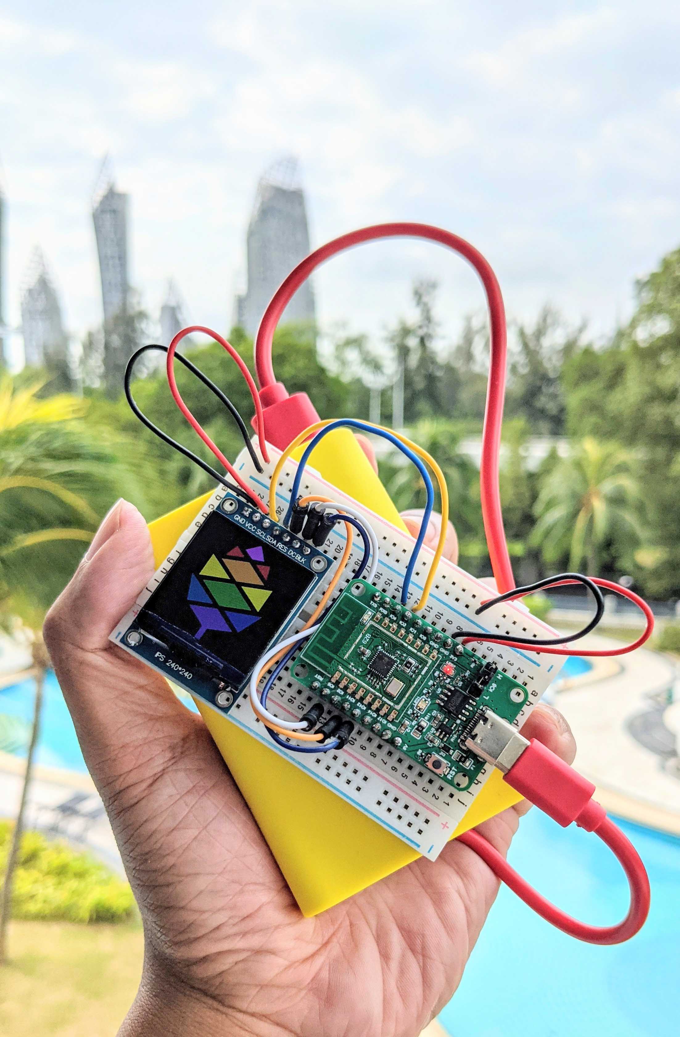
PineCone BL602 with ST7789 Display powered by battery
Exciting things coming up…
LoRa on BL602: We shall connect Semtech SX1276 to BL602 to achieve Triple Wireless Connectivity… WiFi, Bluetooth LE AND LoRa!
(Many thanks to RAKwireless for providing a LoRa Node for our BL602 experiments!)
BL602 for Education: We shall create more Open-Source Educational Content to make BL602 (and RISC-V) fully accessible to learners around the world.
Hopefully someday we’ll see a Deconstructed PineTime Smartwatch: BL602 (RISC-V, WiFi, Bluetooth LE, LoRa) plus the sensors, actuators and display from a smartwatch… Connected on a Breadboard for easy coding!
UART E-Ink Display: Here’s a quick detour on E-Ink Displays with UART Interfaces…
Meanwhile there’s plenty more code in the BL602 IoT SDK to be deciphered and documented: ADC, DAC, WiFi, Bluetooth LE, …
Come Join Us… Make BL602 Better!
🙏 👍 😀
Got a question, comment or suggestion? Create an Issue or submit a Pull Request here…
lupyuen.github.io/src/display.md
This article is the expanded version of this meandering Twitter Thread
To run a command at startup (like in the photos above and below), modify the function cli_init in demo.c
/// Init the command-line interface
int cli_init(void) {
    //  To run a command at startup, use this...
    test_1("", 0, 0, NULL);
    return 0;
}
If the rendering hangs, lower the SPI Frequency to 2 MHz. (But why???)
By default, firmware created by the BL602 IoT SDK will NOT show Assertion Failure messages.
So this code…
#include <assert.h>

//  Stop with an assertion failure
assert(false);
…Will fail silently, without any messages, and loop forever.
(Not so productive for troubleshooting firmware problems!)
To show Assertion Failure messages, we add this function to our BL602 programs: demo.c
/// TODO: We now show assertion failures
/// in development. For production, comment
/// out this function to use the system default,
/// which loops forever without messages.
void __assert_func(const char *file, int line,
    const char *func, const char *failedexpr)
{
    //  Show the assertion failure, file,
    //  line, function name
	printf("Assertion Failed \"%s\": file \"%s\", line %d%s%s\r\n",
        failedexpr, file, line, func ? ", function: " : "",
        func ? func : "");

	//  Loop forever, do not pass go,
    //  do not collect $200
	for (;;) {}
}Here’s the script I use on macOS to automate the building, flashing and running of BL602 firmware: run.sh
#!/usr/bin/env bash
##  macOS script to build, flash and run BL602 Firmware

set -e  #  Exit when any command fails
set -x  #  Echo commands

##  Build for BL602
export CONFIG_CHIP_NAME=BL602

##  Where BL602 IoT SDK is located
export BL60X_SDK_PATH=$PWD/../..

##  Where blflash is located
export BLFLASH_PATH=$PWD/../../../blflash

##  Build the firmware
make

##  Copy firmware to blflash
cp build_out/sdk_app_st7789.bin $BLFLASH_PATH

##  Flash the firmware
pushd $BLFLASH_PATH
blflash flash build_out/sdk_app_st7789.bin \
    --port /dev/tty.usbserial-1420 \
    --initial-baud-rate 230400 \
    --baud-rate 230400
sleep 5
popd

##  Run the firmware
open -a CoolTerm
Note that we need to flip the jumper for GPIO 8 and press the Reset Button, before and after flashing the firmware.
Let’s cover the remaining ST7789 functions for Reset, Backlight and Delay.
We execute a Hard Reset of ST7789 Display by toggling the Reset Pin to High, then Low, then High again…
From display.c
/// Reset the display controller
static int hard_reset(void) {
    //  Toggle the Reset Pin: High, Low, High
    int rc;
    rc = bl_gpio_output_set(DISPLAY_RST_PIN, 1);  assert(rc == 0);
    rc = bl_gpio_output_set(DISPLAY_RST_PIN, 0);  assert(rc == 0);
    rc = bl_gpio_output_set(DISPLAY_RST_PIN, 1);  assert(rc == 0);
    return 0;
}To switch on the backlight, we set the Backlight Pin to High…
From display.c
/// Switch on backlight
int backlight_on(void) {
    //  Set the Backlight Pin to High
    int rc = bl_gpio_output_set(DISPLAY_BLK_PIN, 1);
    assert(rc == 0);
    return 0;
Can we have multiple levels of backlight brightness?
Yes! We may configure the Backlight Pin as a PWM Pin (instead of GPIO).
Then set the PWM Duty Cycle to control the brightness. (See this)
To switch off the backlight, we set the Backlight Pin to Low…
From display.c
/// Switch off backlight
int backlight_off(void) {
    //  Set the Backlight Pin to Low
    printf("Set BLK pin %d to low\r\n", DISPLAY_BLK_PIN);
    int rc = bl_gpio_output_set(DISPLAY_BLK_PIN, 0);
    assert(rc == 0);
    return 0;
}This function sleeps for the specified number of milliseconds…
From display.c
/// Delay for the specified number of milliseconds
static void delay_ms(uint32_t ms) {
    //  TODO: Implement delay. For now we write to console, which also introduces a delay.
    printf("TODO Delay %d\r\n", ms);
}
For now we call printf, introduces a short delay because it writes to the UART Port.
But we should fix this once we find the right delay function from BL602 SDK.
Here’s how we configured LVGL for BL602 and ST7789.
We compare the modified and original LVGL configurations…
And the differences are…
This is needed to enable the LVGL configuration…
#if 1
//  Previously #if 0
These are the settings specific to our ST7789 Display Hardware…
/// Number of rows in SPI Transmit and Receive Buffers. Used by display.c and lv_port_disp.c
#define BUFFER_ROWS             (10)
//  Previously non-existent

/* Maximal horizontal and vertical resolution to support by the library.*/
#define LV_HOR_RES_MAX          (240)
#define LV_VER_RES_MAX          (240)
//  Previously 480 and 320

/* Swap the 2 bytes of RGB565 color.
* Useful if the display has a 8 bit interface (e.g. SPI)*/
#define LV_COLOR_16_SWAP   1
//  Previously 0
We lower the Dots Per Inch because we have a tiny display…
/* Dot Per Inch: used to initialize default sizes.
* E.g. a button with width = LV_DPI / 2 -> half inch wide
* (Not so important, you can adjust it to modify default sizes and spaces)*/
#define LV_DPI              100     /*[px]*/
//  Previously 130
LVGL maintains its own Heap Memory for Widgets. We’re reserving 4 KB of RAM for LVGL Heap Memory.
If we run out of Heap Memory, increase this value.
/* Size of the memory used by `lv_mem_alloc` in bytes (>= 2kB)*/
#define LV_MEM_SIZE    (4U * 1024U)
//  Previously (32U * 1024U)
This will be useful when we have a touchscreen like PineTime…
/* Drag throw slow-down in [%]. Greater value -> faster slow-down */
#define LV_INDEV_DEF_DRAG_THROW           20
//  Previously 10
For efficiency we disable shadows…
/* 1: Enable shadow drawing on rectangles*/
#define LV_USE_SHADOW           0
//  Previously 1
We’re not using a GPU…
/* 1: Enable GPU interface*/
#define LV_USE_GPU              0   /*Only enables `gpu_fill_cb` and `gpu_blend_cb` in the disp. drv- */
//  Previously 1
We don’t have a file system…
/* 1: Enable file system (might be required for images */
#define LV_USE_FILESYSTEM       0
//  Previously 1
The user_data field is useful for porting LVGL apps from other platforms (like InfiniTime)…
/*1: Add a `user_data` to drivers and objects*/
#define LV_USE_USER_DATA        1
//  Previously 1
We enable logging. Switch this to 0 in production…
/*1: Enable the log module*/
#define LV_USE_LOG      1  //  TODO: Should be set to 0 for production
//  Previously 0
We enable detailed logging for easier troubleshooting…
/* How important log should be added:
* LV_LOG_LEVEL_TRACE       A lot of logs to give detailed information
* LV_LOG_LEVEL_INFO        Log important events
* LV_LOG_LEVEL_WARN        Log if something unwanted happened but didn't cause a problem
* LV_LOG_LEVEL_ERROR       Only critical issue, when the system may fail
* LV_LOG_LEVEL_NONE        Do not log anything
*/
#define LV_LOG_LEVEL    LV_LOG_LEVEL_TRACE
//  Previously LV_LOG_LEVEL_WARN
(Normally we don’t enable detailed logging with LVGL on embedded devices… But BL602 seems surprisingly capable, so we turn it on)
We show log messages with printf…
/* 1: Print the log with 'printf';
* 0: user need to register a callback with `lv_log_register_print_cb`*/
#define LV_LOG_PRINTF   1
//  Previously 0
We validate LVGL parameters. Switch this to 0 in production…
/* If Debug is enabled LittelvGL validates the parameters of the functions.
* If an invalid parameter is found an error log message is printed and
* the MCU halts at the error. (`LV_USE_LOG` should be enabled)
* If you are debugging the MCU you can pause
* the debugger to see exactly where the issue is.
*
* The behavior of asserts can be overwritten by redefining them here.
* E.g. #define LV_ASSERT_MEM(p)  <my_assert_code>
*/
#define LV_USE_DEBUG        1
//  Previously 0
We validate LVGL Styles. This is useful when porting apps from previous versions of LVGL, because LVGL Styles have been revamped between Versions 6 and 7…
/*Check if the styles are properly initialized. (Fast)*/
#define LV_USE_ASSERT_STYLE     1
//  Previously 0
We change the Default Font from size 14 to 24. We will probably change the Font Size to support different types of apps…
#define LV_FONT_MONTSERRAT_14    0
//  Previously 1

#define LV_FONT_MONTSERRAT_24    1
//  Previously 0

#define LV_THEME_DEFAULT_FONT_SMALL         &lv_font_montserrat_24
#define LV_THEME_DEFAULT_FONT_NORMAL        &lv_font_montserrat_24
#define LV_THEME_DEFAULT_FONT_SUBTITLE      &lv_font_montserrat_24
#define LV_THEME_DEFAULT_FONT_TITLE         &lv_font_montserrat_24
//  Previously &lv_font_montserrat_14
We select Dark Material as the Default Theme. Which is odd because our screens look like Light Material…
#define LV_THEME_DEFAULT_FLAG               LV_THEME_MATERIAL_FLAG_DARK
//  Previously LV_THEME_MATERIAL_FLAG_LIGHT
Since our display is tiny, we break long words…
/* If a word is at least this long, will break wherever "prettiest"
* To disable, set to a value <= 0 */
#define LV_TXT_LINE_BREAK_LONG_LEN          12
//  Previously 0
We don’t need no precise lines for our tiny display…
/* Draw line more precisely at cost of performance.
* Useful if there are lot of lines any minor are visible
* 0: No extra precision
* 1: Some extra precision
* 2: Best precision
*/
#define LV_LINEMETER_PRECISE    0
//  Previously 1