📝 11 May 2021
Today we shall connect PineCone BL602 RISC-V Board to the LoRaWAN Network… With the Pine64 RFM90 LoRa Module based on Semtech SX1262.
This will bring us one step closer to building low-power, long-range LoRaWAN IoT Devices with BL602.
The LoRaWAN Firmware in this article will run on PineCone, Pinenut and Any BL602 Board.

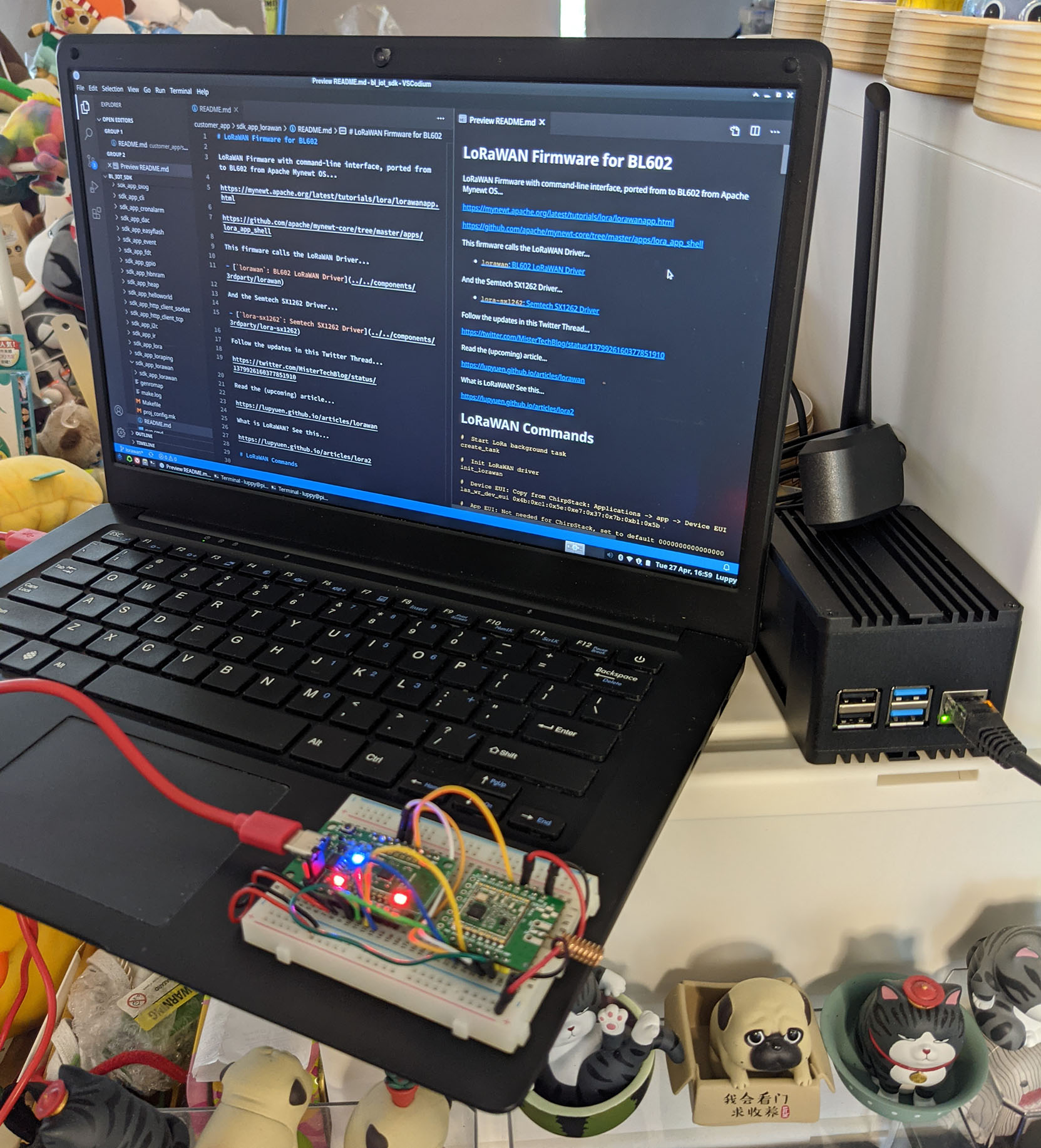
PineCone BL602 RISC-V Board with Pine64 RFM90 LoRa Module (centre), PineBook Pro (left) and RAKwireless WisGate D4H LoRaWAN Gateway (right)
Connect BL602 to Pine64 (HopeRF) RFM90 or Semtech SX1262 as follows…
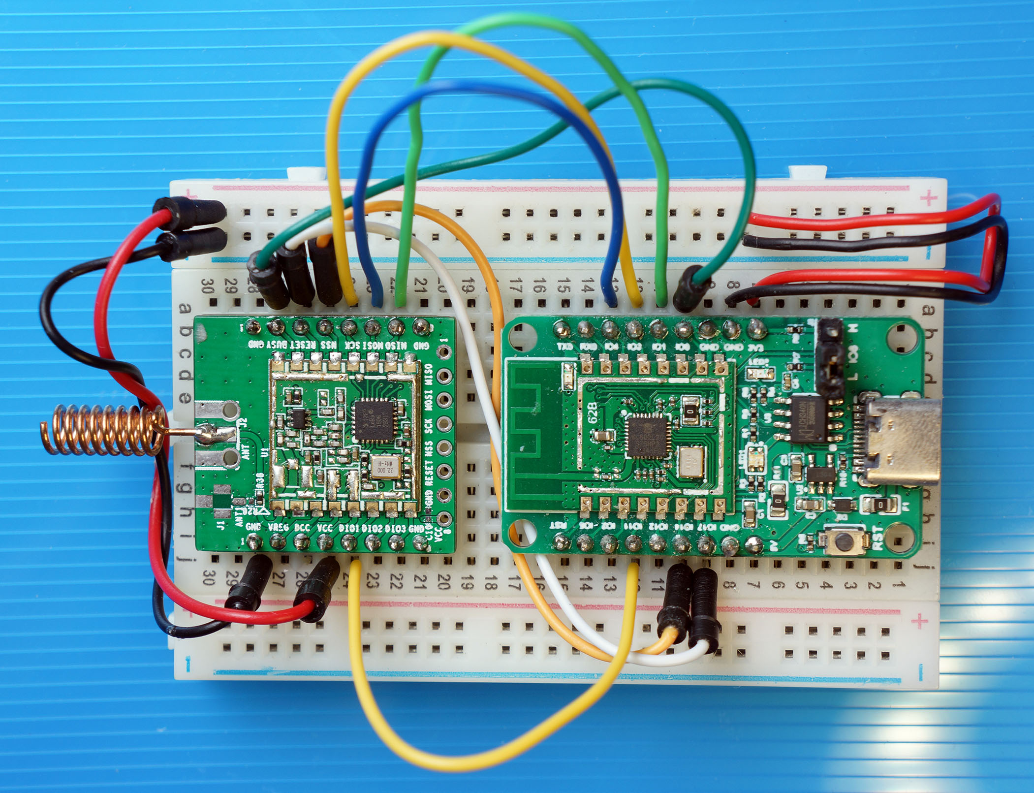
| BL602 Pin | RFM90 / SX1262 Pin | Wire Colour |
|---|---|---|
GPIO 0 | BUSY | Dark Green |
GPIO 1 | ISO (MISO) | Light Green (Top) |
GPIO 2 | Do Not Connect | (Unused Chip Select) |
GPIO 3 | SCK | Yellow (Top) |
GPIO 4 | OSI (MOSI) | Blue (Top) |
GPIO 11 | DIO1 | Yellow (Bottom) |
GPIO 14 | NSS | Orange |
GPIO 17 | RST | White |
3V3 | 3.3V | Red |
GND | GND | Black |
CAUTION: Always connect the Antenna before Powering On… Or the LoRa Module may get damaged! See this
Here’s a closer look at the pins connected on BL602…
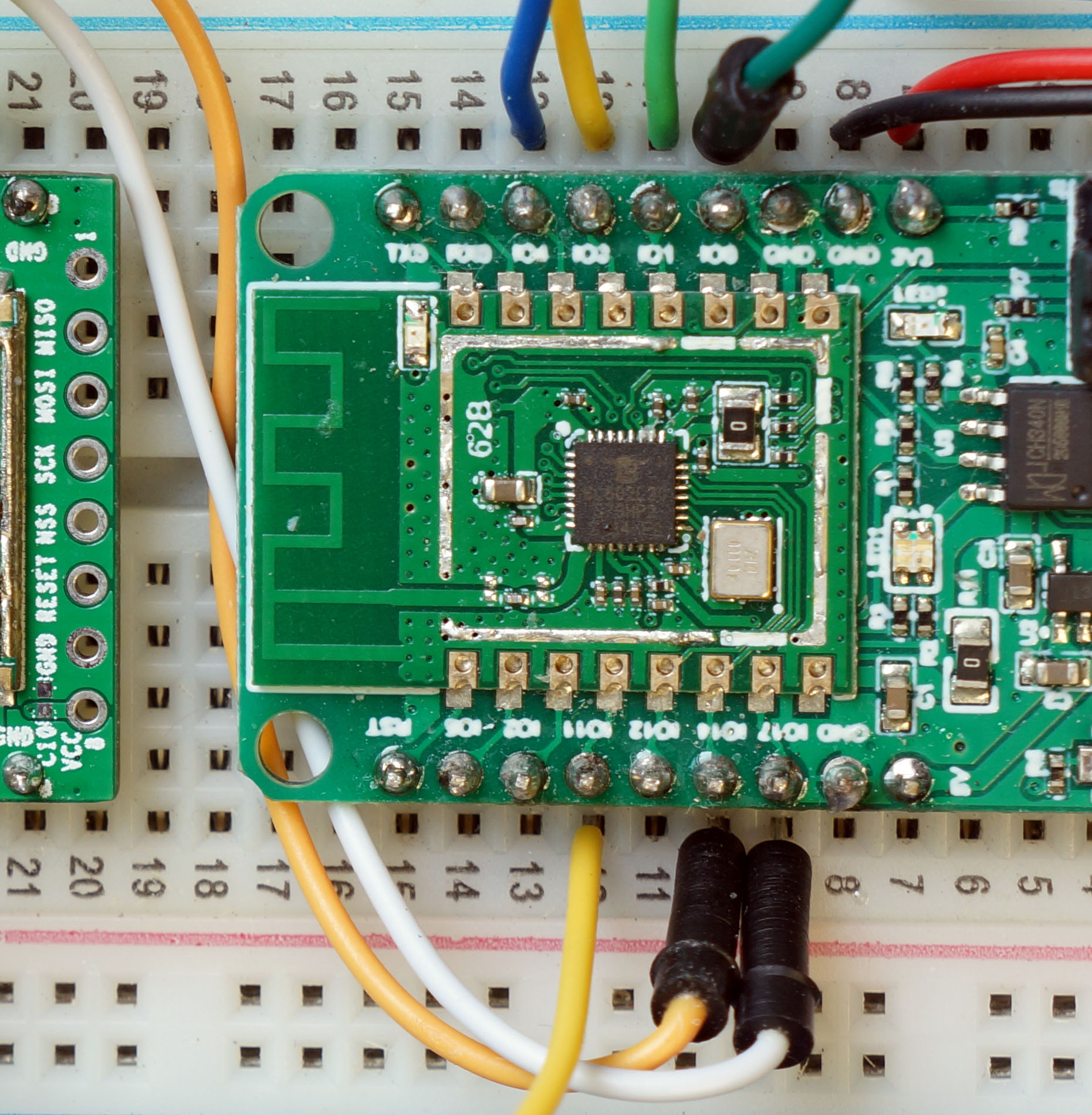
Why is BL602 Pin 2 unused?
GPIO 2 is the Unused SPI Chip Select on BL602.
We won’t use this pin because we’ll control Chip Select ourselves on GPIO 14. (See this)
Here are the pins connected on our LoRa Module: RFM90 or SX1262…
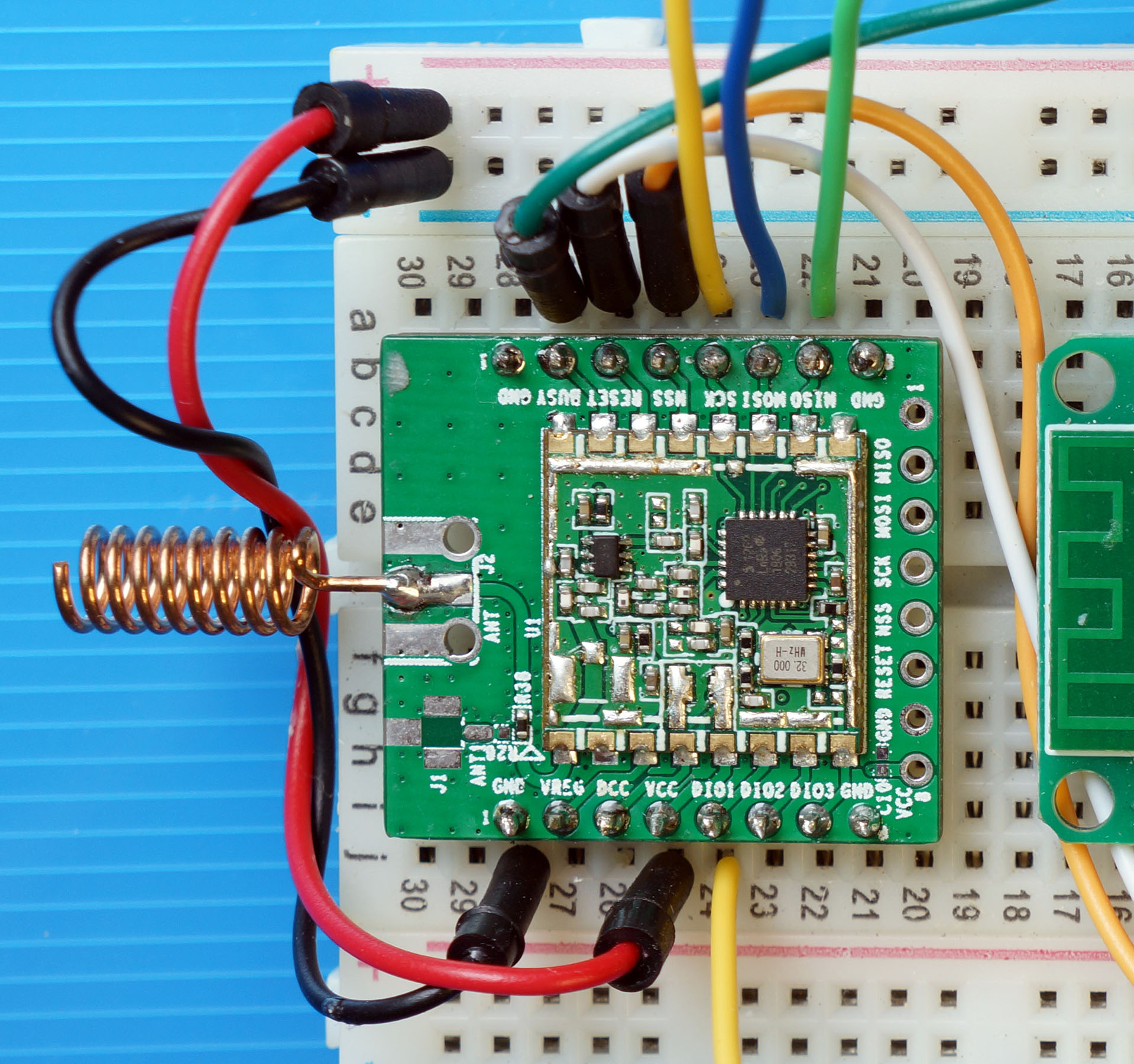
What’s Pin DIO1?
Our LoRa Module shifts Pin DIO1 from Low to High to signal that a LoRa Packet has been transmitted or received.
We shall configure BL602 to trigger a GPIO Interrupt when Pin DIO1 shifts from Low to High.
The BL602 Driver for RFM90 / SX1262 is located here…
Let’s study the source code and learn how the driver is called by our Demo Firmware to transmit and receive LoRa Packets…
Our LoRa Driver has 3 layers: Radio Interface, Transceiver Interface and Board Interface…
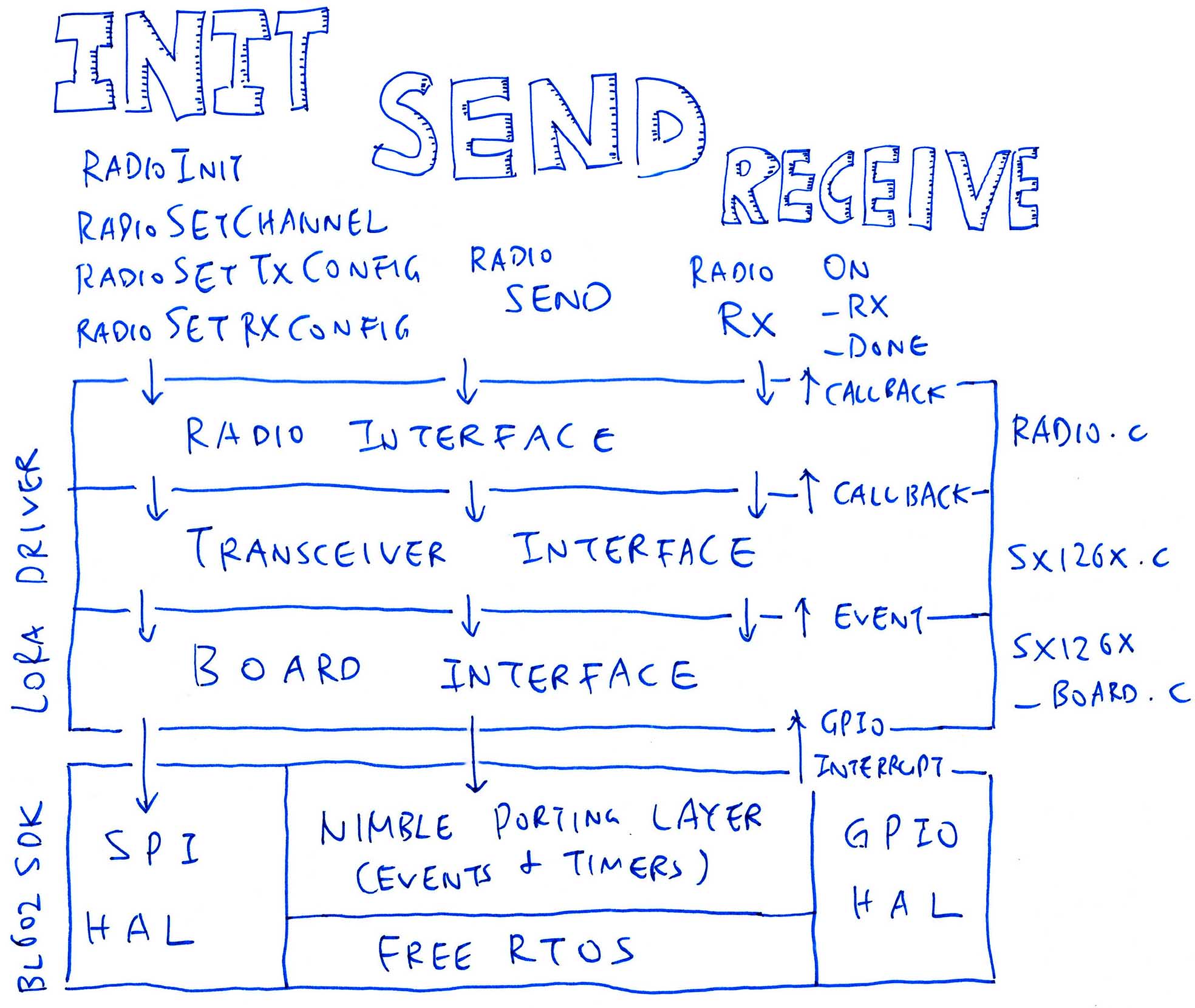
Exposes the LoRa Radio Functions that will initialise the transceiver (RadioInit), send a LoRa Packet (RadioSend) and receive a LoRa Packet (RadioRx).
Our Demo Firmware calls the Radio Interface to send and receive LoRa Packets. (Our LoRaWAN Driver calls the Radio Interface too)
The Radio Interface is generic and works for various LoRa Transceivers (like SX1276).
Transceiver Interface: sx126x.c
Provides the functions specific to the SX1262 Transceiver: SX126xInit, SX126xSendPayload, SX126xSetRx, …
Called by the Radio Interface.
Board Interface: sx126x-board.c
Exposes the functions specific to our BL602 Board: SPI, GPIO, Events and Timers.
SPI and GPIO Functions are implemented with the SPI and GPIO Hardware Abstraction Layers (HALs) from the BL602 IoT SDK.
Events and Timers are implemented with the NimBLE Porting Layer, a library that simplifies the FreeRTOS multitasking functions from the BL602 IoT SDK.
Called by the Transceiver Interface.
The LoRa Driver was ported to BL602 from Semtech’s Reference Implementation of the SX1262 Driver. (See this)
(Note on LoRa vs LoRaWAN: We configure LoRaWAN via Makefile, not #define. Skip this section if we’re using LoRaWAN.)
We set the LoRa Frequency in demo.c like so…
/// TODO: We are using LoRa Frequency 923 MHz
/// for Singapore. Change this for your region.
#define USE_BAND_923
Change USE_BAND_923 to USE_BAND_433, 780, 868 or 915. Here’s the complete list…
#if defined(USE_BAND_433)
  #define RF_FREQUENCY               434000000 /* Hz */
#elif defined(USE_BAND_780)
  #define RF_FREQUENCY               780000000 /* Hz */
#elif defined(USE_BAND_868)
  #define RF_FREQUENCY               868000000 /* Hz */
#elif defined(USE_BAND_915)
  #define RF_FREQUENCY               915000000 /* Hz */
#elif defined(USE_BAND_923)
  #define RF_FREQUENCY               923000000 /* Hz */
#else
  #error "Please define a frequency band in the compiler options."
#endif
The LoRa Parameters are also defined in demo.c
/// LoRa Parameters
#define LORAPING_TX_OUTPUT_POWER            14        /* dBm */

#define LORAPING_BANDWIDTH                  0         /* [0: 125 kHz, */
                                                      /*  1: 250 kHz, */
                                                      /*  2: 500 kHz, */
                                                      /*  3: Reserved] */
#define LORAPING_SPREADING_FACTOR           7         /* [SF7..SF12] */
#define LORAPING_CODINGRATE                 1         /* [1: 4/5, */
                                                      /*  2: 4/6, */
                                                      /*  3: 4/7, */
                                                      /*  4: 4/8] */
#define LORAPING_PREAMBLE_LENGTH            8         /* Same for Tx and Rx */
#define LORAPING_SYMBOL_TIMEOUT             5         /* Symbols */
#define LORAPING_FIX_LENGTH_PAYLOAD_ON      false
#define LORAPING_IQ_INVERSION_ON            false

#define LORAPING_TX_TIMEOUT_MS              3000    /* ms */
#define LORAPING_RX_TIMEOUT_MS              5000    /* ms */
#define LORAPING_BUFFER_SIZE                64      /* LoRa message size */
These should match the LoRa Parameters used by the LoRa Transmitter / Receiver.
I used this LoRa Transmitter and Receiver (based on RAKwireless WisBlock) for testing our LoRa Driver…
“RAKwireless WisBlock talks LoRa with PineCone BL602 RISC-V Board”
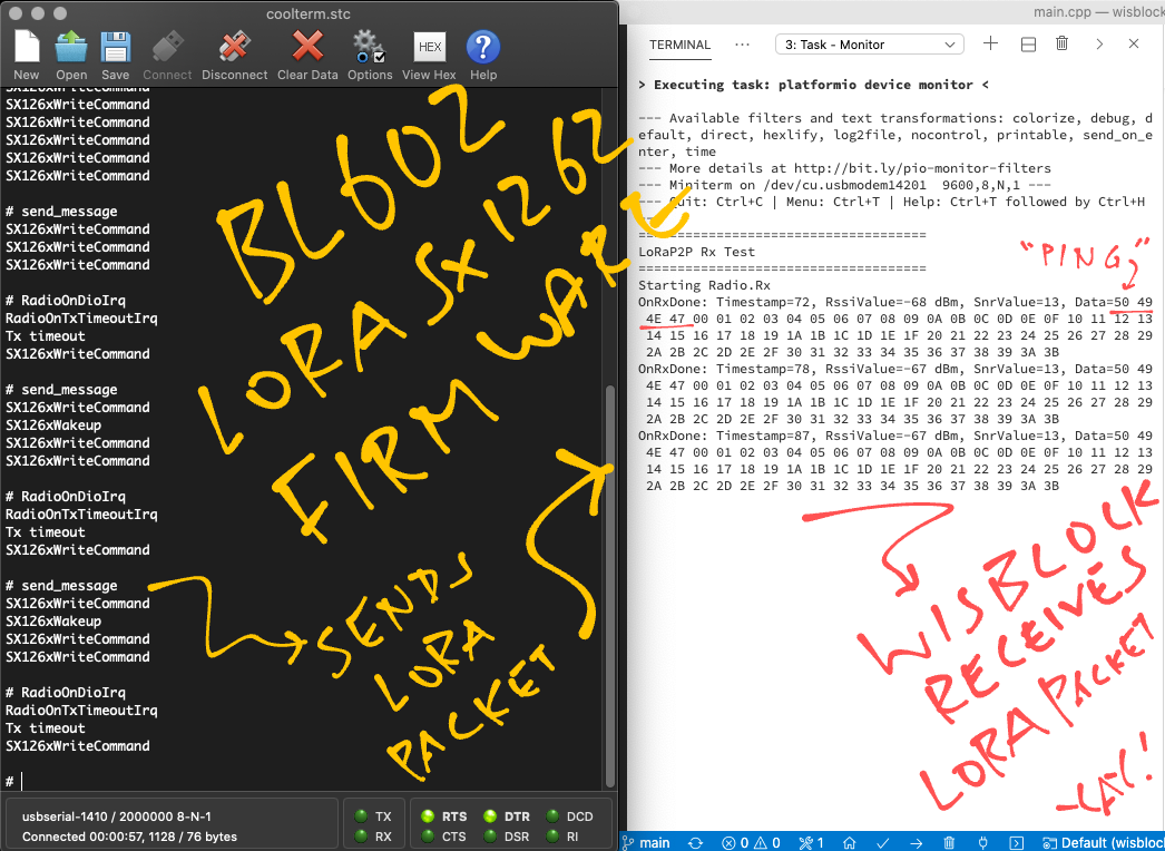
“RAKwireless WisBlock Transmitter”
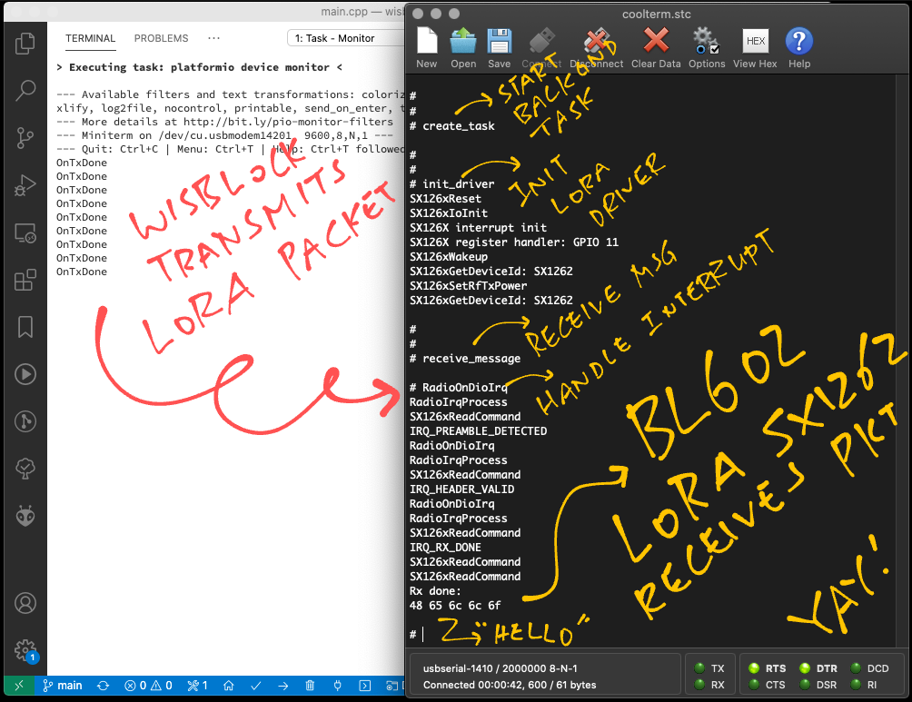
(Note on LoRa vs LoRaWAN: Our LoRaWAN Driver initialises the LoRa Transceiver for us, when we run the init_lorawan command. Skip this section if we’re using LoRaWAN.)
The init_driver command in our Demo Firmware initialises the LoRa Transceiver like so: demo.c
/// Command to initialise the LoRa Driver.
/// Assume that create_task has been called to init the Event Queue.
static void init_driver(char *buf, int len, int argc, char **argv) {
  //  Set the LoRa Callback Functions
  RadioEvents_t radio_events;
  memset(&radio_events, 0, sizeof(radio_events));  //  Must init radio_events to null, because radio_events lives on stack!
  radio_events.TxDone    = on_tx_done;     //  Packet has been transmitted
  radio_events.RxDone    = on_rx_done;     //  Packet has been received
  radio_events.TxTimeout = on_tx_timeout;  //  Transmit Timeout
  radio_events.RxTimeout = on_rx_timeout;  //  Receive Timeout
  radio_events.RxError   = on_rx_error;    //  Receive Error
Here we set the Callback Functions that will be called when a LoRa Packet has been transmitted or received, also when we encounter a transmit / receive timeout or error.
(We’ll see the Callback Functions in a while)
Next we initialise the LoRa Transceiver and set the LoRa Frequency…
  //  Init the SPI Port and the LoRa Transceiver
  Radio.Init(&radio_events);

  //  Set the LoRa Frequency
  Radio.SetChannel(RF_FREQUENCY);
We set the LoRa Transmit Parameters…
  //  Configure the LoRa Transceiver for transmitting messages
  Radio.SetTxConfig(
    MODEM_LORA,
    LORAPING_TX_OUTPUT_POWER,
    0,        //  Frequency deviation: Unused with LoRa
    LORAPING_BANDWIDTH,
    LORAPING_SPREADING_FACTOR,
    LORAPING_CODINGRATE,
    LORAPING_PREAMBLE_LENGTH,
    LORAPING_FIX_LENGTH_PAYLOAD_ON,
    true,     //  CRC enabled
    0,        //  Frequency hopping disabled
    0,        //  Hop period: N/A
    LORAPING_IQ_INVERSION_ON,
    LORAPING_TX_TIMEOUT_MS
  );
Finally we set the LoRa Receive Parameters…
  //  Configure the LoRa Transceiver for receiving messages
  Radio.SetRxConfig(
    MODEM_LORA,
    LORAPING_BANDWIDTH,
    LORAPING_SPREADING_FACTOR,
    LORAPING_CODINGRATE,
    0,        //  AFC bandwidth: Unused with LoRa
    LORAPING_PREAMBLE_LENGTH,
    LORAPING_SYMBOL_TIMEOUT,
    LORAPING_FIX_LENGTH_PAYLOAD_ON,
    0,        //  Fixed payload length: N/A
    true,     //  CRC enabled
    0,        //  Frequency hopping disabled
    0,        //  Hop period: N/A
    LORAPING_IQ_INVERSION_ON,
    true      //  Continuous receive mode
  );
}
The “Radio” functions are defined in radio.c …
RadioInit: Init LoRa Transceiver
RadioSetChannel: Set LoRa Frequency
RadioSetTxConfig: Set LoRa Transmit Configuration
RadioSetRxConfig: Set LoRa Receive Configuration
(Note on LoRa vs LoRaWAN: Our LoRaWAN Driver calls the LoRa Driver to transmit LoRa Packets, when we run the las_join and las_app_tx commands. Skip this section if we’re using LoRaWAN to transmit data.)
To transmit a LoRa Packet, the send_message command in our Demo Firmware calls send_once in demo.c …
/// Command to send a LoRa message. Assume that the LoRa Transceiver driver has been initialised.
static void send_message(char *buf, int len, int argc, char **argv) {
  //  Send the "PING" message
  send_once(1);
}
send_once prepares a LoRa Packet containing the string “PING”…
From demo.c :
/// We send a "PING" message and expect a "PONG" response
const uint8_t loraping_ping_msg[] = "PING";
const uint8_t loraping_pong_msg[] = "PONG";

/// 64-byte buffer for our LoRa message
static uint8_t loraping_buffer[LORAPING_BUFFER_SIZE];

/// Send a LoRa message. If is_ping is 0, send "PONG". Otherwise send "PING".
static void send_once(int is_ping) {
  //  Copy the "PING" or "PONG" message
  //  to the transmit buffer
  if (is_ping) {
    memcpy(loraping_buffer, loraping_ping_msg, 4);
  } else {
    memcpy(loraping_buffer, loraping_pong_msg, 4);
  }
Then pads the packet with values 0, 1, 2, …
  //  Fill up the remaining space in the
  //  transmit buffer (64 bytes) with values
  //  0, 1, 2, ...
  for (int i = 4; i < sizeof loraping_buffer; i++) {
    loraping_buffer[i] = i - 4;
  }
And transmits the LoRa Packet…
  //  Send the transmit buffer (64 bytes)
  Radio.Send(loraping_buffer, sizeof loraping_buffer);
}When the LoRa Packet is transmitted, the LoRa Driver calls our Callback Function on_tx_done …
From demo.c :
/// Callback Function that is called when our LoRa message has been transmitted
static void on_tx_done(void) {
  //  Log the success status
  loraping_stats.tx_success++;

  //  Switch the LoRa Transceiver to
  //  low power, sleep mode
  Radio.Sleep();
}
Here we log the number of packets transmitted, and put the LoRa Transceiver to low power, sleep mode.
(RadioSleep is explained here)
(Note on LoRa vs LoRaWAN: Our LoRaWAN Driver calls the LoRa Driver to receive LoRa Packets, when we run the las_join and las_app_tx commands. Skip this section if we’re using LoRaWAN to receive data.)
Here’s how the receive_message command in our Demo Firmware receives a LoRa Packet: demo.c
/// Command to receive a LoRa message. Assume that LoRa Transceiver driver has been initialised.
/// Assume that create_task has been called to init the Event Queue.
static void receive_message(char *buf, int len, int argc, char **argv) {
  //  Receive a LoRa message within the timeout period
  Radio.Rx(LORAPING_RX_TIMEOUT_MS);  //  Timeout in 5 seconds
}When the LoRa Driver receives a LoRa Packet, it calls our Callback Function on_rx_done …
From demo.c :
/// Callback Function that is called when a LoRa message has been received
static void on_rx_done(
  uint8_t *payload,  //  Buffer containing received LoRa message
  uint16_t size,     //  Size of the LoRa message
  int16_t rssi,      //  Signal strength
  int8_t snr) {      //  Signal To Noise ratio

  //  Switch the LoRa Transceiver to low power, sleep mode
  Radio.Sleep();

  //  Log the signal strength, signal to noise ratio
  loraping_rxinfo_rxed(rssi, snr);
on_rx_done switches the LoRa Transceiver to low power, sleep mode and logs the received packet.
Next it copies the received packet into a buffer…
  //  Copy the received packet
  if (size > sizeof loraping_buffer) {
    size = sizeof loraping_buffer;
  }
  loraping_rx_size = size;
  memcpy(loraping_buffer, payload, size);
Finally it dumps the buffer containing the received packet…
  //  Dump the contents of the received packet
  for (int i = 0; i < loraping_rx_size; i++) {
    printf("%02x ", loraping_buffer[i]);
  }
  printf("\r\n");
}
What happens when we don’t receive a packet in 5 seconds?
The LoRa Driver calls our Callback Function on_rx_timeout …
From demo.c :
/// Callback Function that is called when no LoRa messages could be received due to timeout
static void on_rx_timeout(void) {
  //  Switch the LoRa Transceiver to low power, sleep mode
  Radio.Sleep();

  //  Log the timeout
  loraping_stats.rx_timeout++;
  loraping_rxinfo_timeout();
}
We switch the LoRa Transceiver into sleep mode and log the timeout.
The LoRa Transceiver (RFM90 / SX1262) triggers a GPIO Interrupt on BL602 when it receives a LoRa Packet…
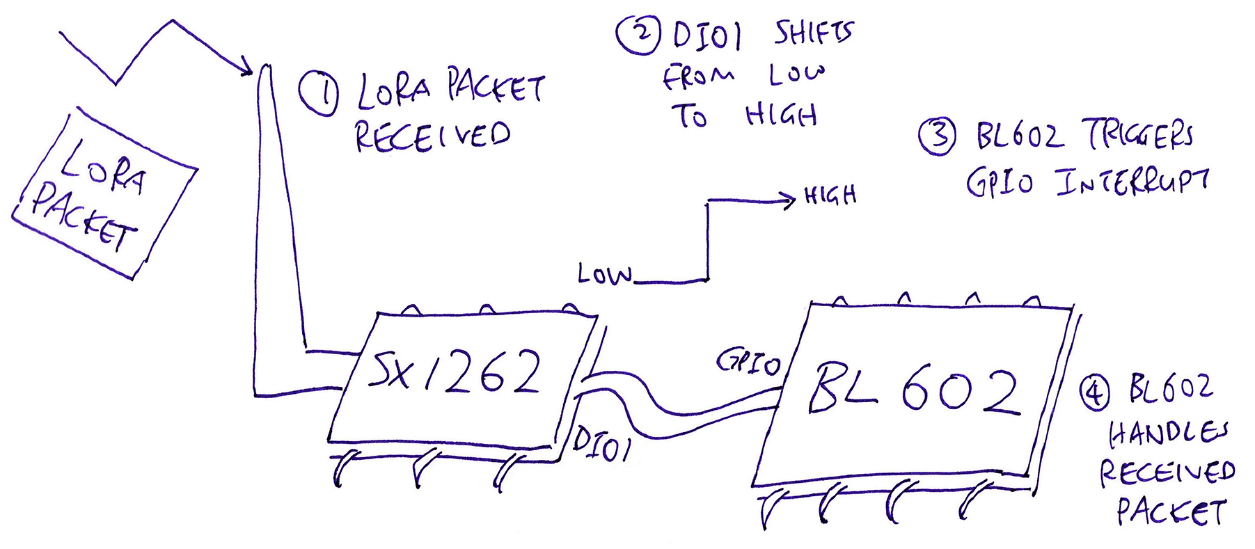
For safety we forward the GPIO Interrupt to a Background Task via an Event Queue…
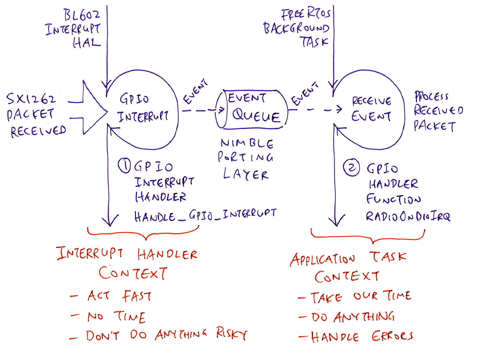
So that the GPIO Interrupt is handled in the Application Context, where it’s safe to call SPI Functions, printf and other nice things.
The GPIO Interrupt Handling is explained in the Appendix…
The Multitasking Functions (Event Queue and Background Task) are provided by the NimBLE Porting Layer library…
We’ve seen the LoRa Transceiver Driver (for RFM90 / SX1262)… Now let’s watch how the LoRaWAN Driver wraps around the LoRa Transceiver Driver to do secure, managed LoRaWAN Networking.
The BL602 Driver for LoRaWAN is located here…
We shall study the source code and learn how the LoRaWAN Driver is called by our demo firmware to join the LoRaWAN Network and transmit data packets…
Our BL602 Driver for LoRaWAN has layers (like Onions, Shrek and Kueh Lapis): Application Layer, Node Layer and Medium Access Control Layer…
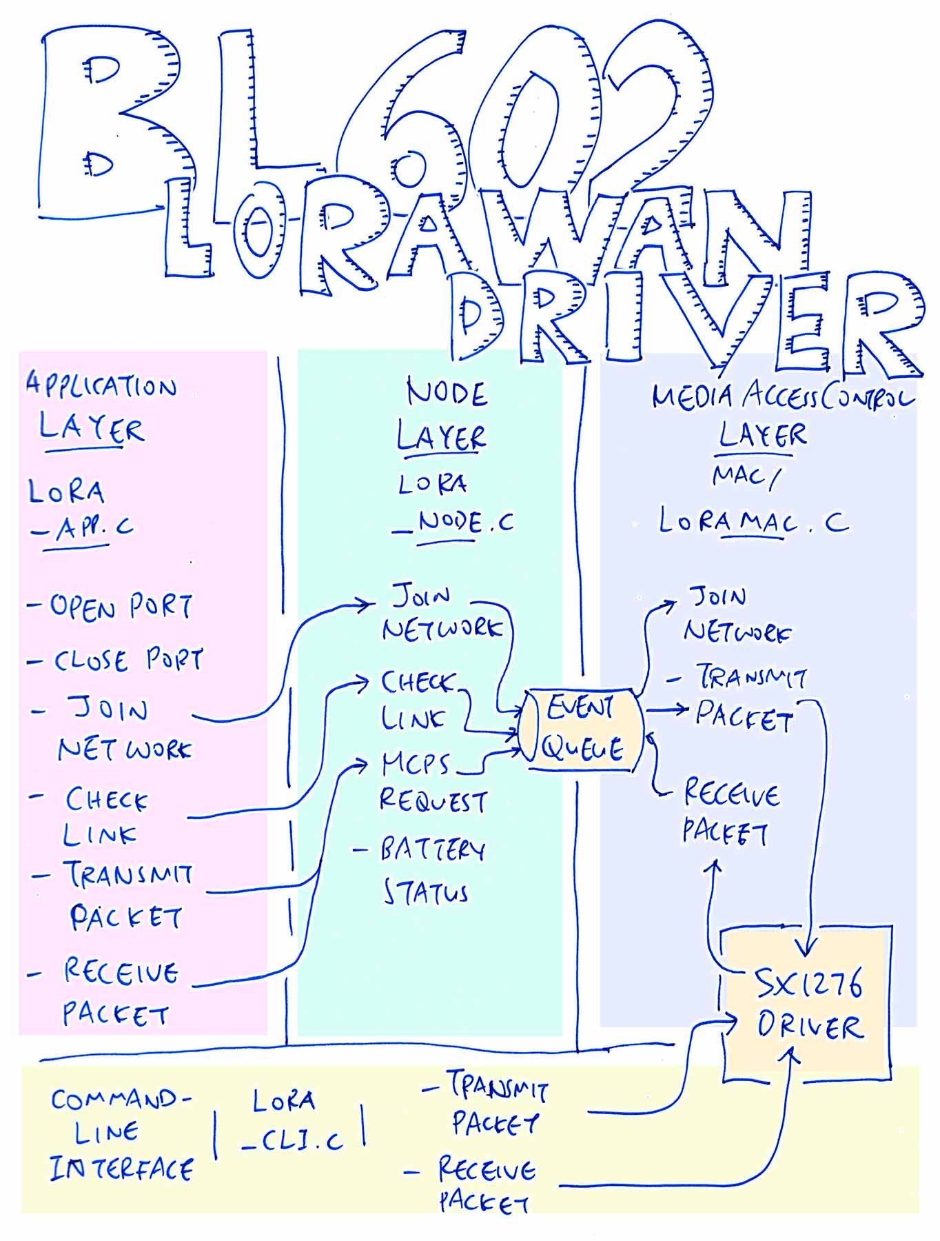
The Application Layer exposes functions for our Demo Firmware to…
Join the LoRaWAN Network: lora_app_join
Open a LoRaWAN Application Port: lora_app_port_open
Transmit a LoRaWAN Data Packet: lora_app_port_send
The Node Layer is called by the Application Layer to handle LoRaWAN Networking requests.
The Node Layer channels the networking requests to the Medium Access Control Layer via an Event Queue (provided by the NimBLE Porting Layer).
Medium Access Control Layer: LoRaMac.c
The Medium Access Control Layer implements the LoRaWAN Networking functions by calling the LoRa Transceiver Driver (for RFM90 / SX1262).
(Yep the Medium Access Control Layer calls the “Radio” functions we’ve seen in the previous chapter)
This layer is fully aware of the LoRa Frequencies and the Encoding Schemes that should be used in each world region. And it enforces LoRaWAN Security (like encryption and authentication of messages).
The Medium Access Control Layer runs as a Background Task, communicating with the Node Layer in a queued, asynchronous way via an Event Queue.
We’re not using the Command-Line Interface lora_cli.c that’s bundled with our LoRaWAN Driver.
Instead we’re using the Command-Line Interface that’s coded inside our Demo Firmware.
The LoRaWAN Driver was ported to BL602 from Apache Mynewt OS. (See this)
(This implementation of the LoRaWAN Driver seems outdated. There is a newer reference implementation by Semtech. See this)
Before transmitting a LoRaWAN Data Packet, our BL602 gadget needs to join the LoRaWAN Network.
(It’s like connecting to a WiFi Network, authenticated by a security key)
In the Demo Firmware, we enter this command to join the LoRaWAN Network (up to 3 attempts)…
las_join 3Let’s study what happens inside the las_join command…
From lorawan.c :
/// `las_join` command will send a Join Network Request
void las_cmd_join(char *buf0, int len0, int argc, char **argv) {
  ...
  //  Send a Join Network Request
  int rc = lora_app_join(
    g_lora_dev_eui,  //  Device EUI
    g_lora_app_eui,  //  Application EUI
    g_lora_app_key,  //  Application Key
    attempts         //  Number of join attempts
  );
To join a LoRaWAN Network we need to have 3 things in our BL602 firmware…
Device EUI: A 64-bit number that uniquely identifies our LoRaWAN Device (BL602)
Application EUI: A 64-bit number that uniquely identifies the LoRaWAN Server Application that will receive our LoRaWAN Data Packets
Application Key: A 128-bit secret key that will authenticate our LoRaWAN Device for that LoRaWAN Server Application
(EUI sounds like a Pungent Durian… But it actually means Extended Unique Identifier)
How do we get the Device EUI, Application EUI and Application Key? We’ll find out in a while.
lora_app_join is defined in the Application Layer of our LoRaWAN Driver: lora_app.c
/// Send a Join Network Request
int lora_app_join(uint8_t *dev_eui, uint8_t *app_eui, uint8_t *app_key, uint8_t trials) {
  //  Omitted: Validate the parameters
  ...

  //  Tell device to start join procedure
  int rc = lora_node_join(dev_eui, app_eui, app_key, trials);
Here we validate the parameters and call lora_node_join.
Now we hop over from the Application Layer to the Node Layer: lora_node.c
/// Perform the join process
int lora_node_join(uint8_t *dev_eui, uint8_t *app_eui, uint8_t *app_key, uint8_t trials) {
  //  Omitted: Check if we have joined the network
  ...

  //  Set the Event parameters
  g_lm_join_ev_arg.dev_eui = dev_eui;
  g_lm_join_ev_arg.app_eui = app_eui;
  g_lm_join_ev_arg.app_key = app_key;
  g_lm_join_ev_arg.trials  = trials;

  //  Send Event to Medium Access Control Layer via Event Queue
  ble_npl_eventq_put(
    g_lora_mac_data.lm_evq,      //  Event Queue
    &g_lora_mac_data.lm_join_ev  //  Event
  );
Here we’re passing a Join Event to the Event Queue that’s provided by the NimBLE Porting Layer.
Again we hop, from the Node Layer to the Medium Access Control Layer: LoRaMac.c
/// Background Task that handles the Event Queue
LoRaMacStatus_t LoRaMacMlmeRequest(MlmeReq_t *mlmeRequest) {
  ...
  //  Check the request type
  switch (mlmeRequest->Type) {
    //  If this is a join request...
    case MLME_JOIN:
      //  Compose and send the join request
      status = Send(&macHdr, 0, NULL);
LoRaMacMlmeRequest runs as a FreeRTOS Background Task, processing the Events that have been enqueued in the Event Queue.
(That’s how the Node Layer and the Medium Access Control Layer collaborate asynchronously)
LoRaMacMlmeRequest calls Send to compose and transmit the Join Request as a LoRa Packet: LoRaMac.c
//  Compose and send a packet
LoRaMacStatus_t Send(LoRaMacHeader_t *macHdr, uint8_t fPort, struct pbuf *om) {
  ...
  //  Prepare the LoRa Packet
  status = PrepareFrame(macHdr, &fCtrl, fPort, om);

  //  Send the LoRa Packet
  status = ScheduleTx();
The call chain goes…
Send → ScheduleTx → SendFrameOnChannel → RadioSend
Eventually the Medium Access Control Layer calls RadioSend (from our LoRa Transceiver Driver) to transmit the Join Request.
(What’s inside the Join Request? Check this out)
And that’s how our LoRaWAN Driver sends a Join Network Request…
LoRaWAN Firmware → Application Layer → Node Layer → Medium Access Control Layer → LoRa Transceiver Driver!
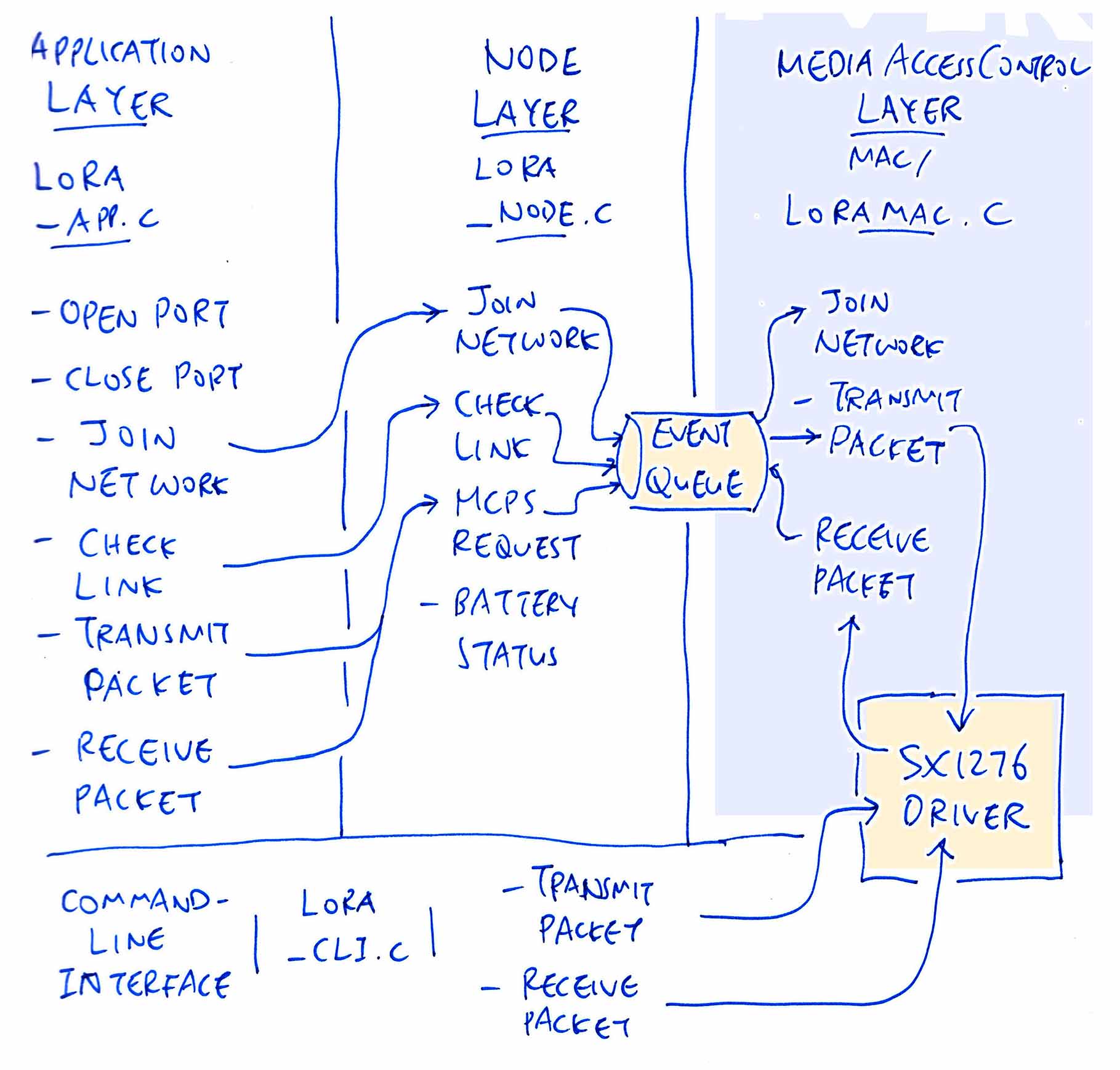
But wait… We’re not done yet!
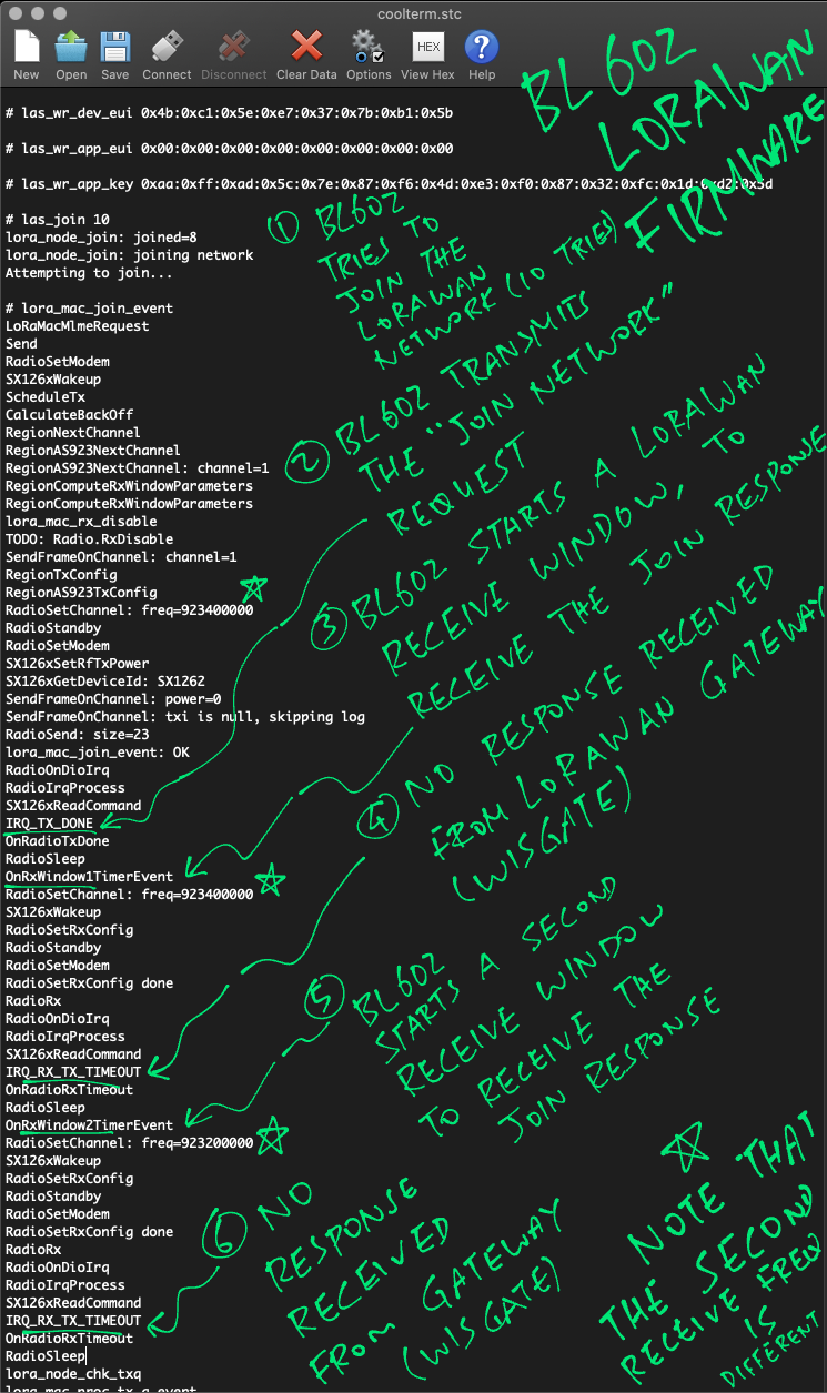
We’ve sent a Join Network Request to the LoRaWAN Gateway… Now we need to wait for the response from the LoRaWAN Gateway.
The Medium Access Control Layer calls RadioRx (from the LoRa Transceiver Driver) to receive the response packet.
When the packet is received, the LoRa Transceiver Driver calls this Callback Function: OnRadioRxDone in LoRaMac.c
/// Callback Function that's called when we receive a LoRa Packet
static void OnRadioRxDone(uint8_t *payload, uint16_t size, int16_t rssi, int8_t snr) {
  //  Put the Receive Event into the Event Queue
  ble_npl_eventq_put(
    lora_node_mac_evq_get(),    //  Event Queue
    &g_lora_mac_radio_rx_event  //  Receive Event
  );

  //  Remember the received data
  g_lora_mac_data.rxbuf     = payload;
  g_lora_mac_data.rxbufsize = size;
OnRadioRxDone adds the Receive Event to the Event Queue for background processing.
Our Background Task receives the Receive Event from the Event Queue and processes the event: LoRaMac.c
/// Process the Receive Event
static void lora_mac_process_radio_rx(struct ble_npl_event *ev) {
  ...
  //  Put radio to sleep
  Radio.Sleep();

  //  Get the payload and size
  payload = g_lora_mac_data.rxbuf;
  size    = g_lora_mac_data.rxbufsize;

  //  Get the header from the received frame
  macHdr.Value = payload[0];

  //  Check the header type
  switch (macHdr.Bits.MType) {
    //  If this is a Join Accept Response...
    case FRAME_TYPE_JOIN_ACCEPT:
      //  Process the Join Accept Response
      lora_mac_join_accept_rxd(payload, size);
      break;
(We assume that the Join Request was accepted by the LoRaWAN Gateway)
lora_mac_process_radio_rx handles the Join Accept Response by calling lora_mac_join_accept_rxd …
From LoRaMac.c :
/// Process the Join Accept Response
static void lora_mac_join_accept_rxd(uint8_t *payload, uint16_t size) {
  ...
  //  Decrypt the response
  LoRaMacJoinDecrypt(payload + 1, size - 1, LoRaMacAppKey, LoRaMacRxPayload + 1);
  ...
  //  Verify the Message Integrity Code
  LoRaMacJoinComputeMic(LoRaMacRxPayload, size - LORAMAC_MFR_LEN, LoRaMacAppKey, &mic);
  ...
  //  Omitted: Update the Join Network Status
  ...
  //  Stop Second Receive Window
  lora_mac_rx_win2_stop();
lora_mac_join_accept_rxd handles the Join Accept Response…
Decrypt the response
Verify the Message Integrity Code
Update the Join Network Status
Stop the Second Receive Window
(More about LoRaWAN Encryption and Message Integrity Code)
What’s a Receive Window?
Here’s what the LoRaWAN Specification says…
LoRaWAN Devices (Class A, like our BL602 gadget) don’t receive packets all the time.
We listen for incoming packets (for a brief moment) only after we transmit a packet. This is called a Receive Window.
We’ve just transmitted a packet (Join Network Request), so we listen for an incoming packet (Join Accept Reponse).
Why do we stop the Second Receive Window?
Now the LoRaWAN Specification actually defines Two Receive Windows…
If we don’t receive a packet in the First Receive Window, we shall listen again (very briefly) in the Second Receive Window.
But since we have received a Join Accept Response in the First Receive Window, we may cancel the Second Receive Window.
And that’s how we handle the Join Network Response from the LoRaWAN Gateway!
(More about LoRaWAN Receive Windows)
Our BL602 gadget has joined the LoRaWAN Network… We’re almost ready to send data packets to the LoRaWAN Gateway! But before that, we need to open a LoRaWAN Application Port.
(It’s like opening a TCP or UDP socket)
In our Demo Firmware we enter this command to open LoRaWAN Application Port Number 2…
las_app_port open 2(Port #2 seems to be a common port used by LoRaWAN Applications)
The las_app_port command calls this function in lorawan.c …
/// `las_app_port open 2` command opens LoRaWAN Application Port 2
void las_cmd_app_port(char *buf0, int len0, int argc, char **argv) {
  ...
  //  If this is an `open` command...
  if (!strcmp(argv[1], "open")) {
    //  Call the LoRaWAN Driver to open the LoRaWAN Application Port
    rc = lora_app_port_open(
      port,                     //  Port Number (2)
      lora_app_shell_txd_func,  //  Callback Function for Transmit
      lora_app_shell_rxd_func   //  Callback Function for Receive
    );
las_cmd_app_port calls our LoRaWAN Driver to open the LoRaWAN Port and provides two Callback Functions…
lora_app_shell_txd_func: Called when a LoRaWAN Packet has been transmitted
lora_app_shell_rxd_func: Called when a LoRaWAN Packet has been received
Here’s how our LoRaWAN Driver opens the LoRaWAN Port: lora_app.c
/// Open a LoRaWAN Application Port. This function will
/// allocate a LoRaWAN port, set port default values for
/// datarate and retries, set the transmit done and
/// received data callbacks, and add port to list of open ports.
int lora_app_port_open(uint8_t port, lora_txd_func txd_cb, lora_rxd_func rxd_cb) {
  ...
  //  Make sure port is not opened
  avail = -1;
  for (i = 0; i < LORA_APP_NUM_PORTS; ++i) {
    //  If port not opened, remember first available
    if (lora_app_ports[i].opened == 0) {
      if (avail < 0) { avail = i; }
    } else {
      //  Make sure port is not already opened
      if (lora_app_ports[i].port_num == port) { return LORA_APP_STATUS_ALREADY_OPEN; }
    }
  }
lora_app_port_open allocates a port object for the requested port number.
Then it sets the port number, receive callback and transmit callback in the port object…
  //  Open port if available
  if (avail >= 0) {
    lora_app_ports[avail].port_num = port;  //  Port Number
    lora_app_ports[avail].rxd_cb = rxd_cb;  //  Receive Callback
    lora_app_ports[avail].txd_cb = txd_cb;  //  Transmit Callback
    lora_app_ports[avail].retries = 8;
    lora_app_ports[avail].opened = 1;
    rc = LORA_APP_STATUS_OK;
  } else {
    rc = LORA_APP_STATUS_ENOMEM;
  }
  return rc;
}
We’re now ready to transmit data packets to LoRaWAN Port #2!
We enter this command into our Demo Firmware to transmit a LoRaWAN Data Packet to port 2, containing 5 bytes (of null)…
las_app_tx 2 5 0The “0” at the end indicates that this is an Unconfirmed Message: We don’t expect any acknowledgement from the LoRaWAN Gateway.
This is the preferred way for a low-power LoRaWAN device to transmit sensor data, since it doesn’t need to wait for the acknowledgement (and consume additional power).
(It’s OK if a LoRaWAN Data Packet gets lost due to noise or inteference… LoRaWAN sensor devices are supposed to transmit data packets periodically anyway)
The las_app_tx command is implemented here: lorawan.c
/// `las_app_tx 2 5 0` command transmits to LoRaWAN Port 2
/// a data packet of 5 bytes, as an Unconfirmed Message (0)
void las_cmd_app_tx(char *buf0, int len0, int argc, char **argv) {
  ...
  //  Allocate a Packet Buffer
  om = lora_pkt_alloc(len);
  ...
  //  Copy the data into the Packet Buffer
  int rc = pbuf_copyinto(
    om,  //  Packet Buffer
    0,   //  Offset into the Packet Buffer
    las_cmd_app_tx_buf,  //  Data to be copied
    len                  //  Data length
  );
  assert(rc == 0);

  //  Transmit the Packet Buffer
  rc = lora_app_port_send(
    port,       //  Port Number
    mcps_type,  //  Message Type: Unconfirmed
    om          //  Packet Buffer
  );
las_cmd_app_tx does the following…
Allocate a Packet Buffer
Copy the transmit data into the Packet Buffer
Transmit the Packet Buffer by calling lora_app_port_send
We use Packet Buffers in the LoRaWAN Driver because they are more efficient for passing packets around. (More about Packet Buffers in the Appendix)
Now we hop from the Demo Firmware into the Application Layer of the LoRaWAN Driver: lora_app.c
/// Send a LoRaWAN Packet to a LoRaWAN Port
int lora_app_port_send(uint8_t port, Mcps_t pkt_type, struct pbuf *om) {
  ...
  //  Find the LoRaWAN port
  lap = lora_app_port_find_open(port);

  //  Set the header in the Packet Buffer
  lpkt = (struct lora_pkt_info *) get_pbuf_header(om, sizeof(struct lora_pkt_info));
  lpkt->port     = port;
  lpkt->pkt_type = pkt_type;
  lpkt->txdinfo.retries = lap->retries;

  //  Call the Node Layer to transmit the Packet Buffer
  lora_node_mcps_request(om);
lora_app_port_send transmits the Packet Buffer by calling lora_node_mcps_request.
Again we hop, from the Application Layer to the Node Layer: lora_node.c
/// Transmit a LoRaWAN Packet by adding it to the Transmit Queue
void lora_node_mcps_request(struct pbuf *om) {
  ...
  //  Add the Packet Buffer to the Transmit Queue
  rc = pbuf_queue_put(
    &g_lora_mac_data.lm_txq,  //  Transmit Queue
    g_lora_mac_data.lm_evq,   //  Event Queue
    om                        //  Packet Buffer
  );
lora_node_mcps_request adds the Packet Buffer to the Transmit Queue, the queue for outgoing packets.
(Our Transmit Queue is implemented as a Packet Buffer Queue. More about Packet Buffer Queues in the Appendix.)
The Background Process receives the Packet Buffer from the Transmit Queue: lora_node.c
/// Process a LoRaWAN Packet from the Transmit Queue
static void lora_mac_proc_tx_q_event(struct ble_npl_event *ev) {
  ...
  //  Get the next Packet Buffer from the Transmit Queue.
  //  STAILQ_FIRST returns the first node of the linked list
  //  See https://github.com/lupyuen/lorawan/blob/main/include/node/bsd_queue.h
  mp = STAILQ_FIRST(&g_lora_mac_data.lm_txq.mq_head);
  ...
  //  Call the Medium Access Layer to transmit the Packet Buffer
  rc = LoRaMacMcpsRequest(om, lpkt);
(Hang in there… We’re almost done!)
lora_mac_proc_tx_q_event passes the Packet Buffer to the Medium Access Control Layer (yep another hop): LoRaMac.c
/// Transmit the Packet Buffer
LoRaMacStatus_t LoRaMacMcpsRequest(struct pbuf *om, struct lora_pkt_info *txi) {
  ...
  //  Send the Packet Buffer
  status = Send(&macHdr, txi->port, om);
LoRaMacMcpsRequest calls Send to transmit the packet.
We’ve seen the Send function earlier, it…
Transmits the packet by calling the LoRa Transceiver Driver
Opens two Receive Windows and listens briefly (twice) for incoming packets
Since this is an Unconfirmed Message, we don’t expect an acknowledgement from the LoRaWAN Gateway.
Both Receive Windows will time out, and that’s perfectly fine.
Aha! So we use a Background Task because of the Receive Windows?
Yes, the Medium Access Control Layer might be busy waiting for a Receive Window to time out before transmitting the next packet.
Our LoRaWAN Driver uses the Background Task and the Transmit Queue to handle the deferred transmission of packets.
(This deferred processing of packets is known as MCPS: MAC Common Part Sublayer. More about this)
Let’s run the LoRaWAN Demo Firmware for BL602 to…
Join a LoRaWAN Network
Open a LoRaWAN Application Port
Send a LoRaWAN Data Packet
Find out which LoRa Frequency we should use for your region…
Download the LoRaWAN firmware and driver source code…
## Download the master branch of lupyuen's bl_iot_sdk
git clone --recursive --branch master https://github.com/lupyuen/bl_iot_sdk
In the customer_app/sdk_app_lorawan folder, edit Makefile and find this setting…
CFLAGS += -DCONFIG_LORA_NODE_REGION=1Change “1” to your LoRa Region…
| Value | Region |
|---|---|
| 0 | No region |
| 1 | AS band on 923MHz |
| 2 | Australian band on 915MHz |
| 3 | Chinese band on 470MHz |
| 4 | Chinese band on 779MHz |
| 5 | European band on 433MHz |
| 6 | European band on 868MHz |
| 7 | South Korean band on 920MHz |
| 8 | India band on 865MHz |
| 9 | North American band on 915MHz |
| 10 | North American band on 915MHz with a maximum of 16 channels |
Then update the GPIO Pin Numbers in…
components/3rdparty/lora-sx1262/include/sx126x-board.hBelow are the GPIO Pin Numbers for the connection shown at the top of this article…
#define SX126X_SPI_SDI_PIN       1  //  SPI Serial Data In Pin  (formerly MISO)
#define SX126X_SPI_SDO_PIN       4  //  SPI Serial Data Out Pin (formerly MOSI)
#define SX126X_SPI_CLK_PIN       3  //  SPI Clock Pin
#define SX126X_SPI_CS_PIN       14  //  SPI Chip Select Pin
#define SX126X_SPI_CS_OLD        2  //  Unused SPI Chip Select Pin
#define SX126X_NRESET           17  //  Reset Pin
#define SX126X_DIO1             11  //  DIO1
#define SX126X_BUSY_PIN          0  //  Busy Pin
#define SX126X_DEBUG_CS_PIN     -1  //  Debug Chip Select Pin, mirrors the High / Low State of SX1262 Chip Select Pin. Set to -1 if not needed.
Build the Firmware Binary File sdk_app_lorawan.bin…
## TODO: Change this to the full path of bl_iot_sdk
export BL60X_SDK_PATH=$HOME/bl_iot_sdk
export CONFIG_CHIP_NAME=BL602

cd bl_iot_sdk/customer_app/sdk_app_lorawan
make

## For WSL: Copy the firmware to /mnt/c/blflash, which refers to c:\blflash in Windows
mkdir /mnt/c/blflash
cp build_out/sdk_app_lorawan.bin /mnt/c/blflash
More details on building bl_iot_sdk
Follow these steps to install blflash…
We assume that our Firmware Binary File sdk_app_lorawan.bin has been copied to the blflash folder.
Set BL602 to Flashing Mode and restart the board…
For PineCone:
Set the PineCone Jumper (IO 8) to the H Position (Like this)
Press the Reset Button
For BL10:
Connect BL10 to the USB port
Press and hold the D8 Button (GPIO 8)
Press and release the EN Button (Reset)
Release the D8 Button
For Ai-Thinker Ai-WB2, Pinenut and MagicHome BL602:
Disconnect the board from the USB Port
Connect GPIO 8 to 3.3V
Reconnect the board to the USB port
Enter these commands to flash sdk_app_lorawan.bin to BL602 over UART…
## For Linux:
blflash flash build_out/sdk_app_lorawan.bin \
    --port /dev/ttyUSB0

## For macOS:
blflash flash build_out/sdk_app_lorawan.bin \
    --port /dev/tty.usbserial-1420 \
    --initial-baud-rate 230400 \
    --baud-rate 230400

## For Windows: Change COM5 to the BL602 Serial Port
blflash flash c:\blflash\sdk_app_lorawan.bin --port COM5
(For WSL: Do this under plain old Windows CMD, not WSL, because blflash needs to access the COM port)
More details on flashing firmware
Set BL602 to Normal Mode (Non-Flashing) and restart the board…
For PineCone:
Set the PineCone Jumper (IO 8) to the L Position (Like this)
Press the Reset Button
For BL10:
For Ai-Thinker Ai-WB2, Pinenut and MagicHome BL602:
Disconnect the board from the USB Port
Connect GPIO 8 to GND
Reconnect the board to the USB port
After restarting, connect to BL602’s UART Port at 2 Mbps like so…
For Linux:
screen /dev/ttyUSB0 2000000For macOS: Use CoolTerm (See this)
For Windows: Use putty (See this)
Alternatively: Use the Web Serial Terminal (See this)
More details on connecting to BL602
Let’s enter some commands to join the LoRaWAN Network and transmit a LoRaWAN Data Packet!
Get the following from the LoRaWAN Gateway: Device EUI, Application EUI and Application Key…
We shall use them in a while to join the LoRaWAN Network.
In the BL602 terminal, press Enter to reveal the command prompt.
First we create the Background Task that will process outgoing and incoming LoRa Packets.
Enter this command…
create_taskThen we initialise our LoRaWAN Driver.
Enter this command…
init_lorawanLet’s get ready to join the LoRaWAN Network. Enter the Device EUI…
las_wr_dev_eui 0x4b:0xc1:0x5e:0xe7:0x37:0x7b:0xb1:0x5bIn ChirpStack: Copy the Device EUI from Applications → app → Device EUI
Enter the Application EUI…
las_wr_app_eui 0x00:0x00:0x00:0x00:0x00:0x00:0x00:0x00ChirpStack doesn’t require an Application EUI, so we set it to zeros.
Enter the Application Key…
las_wr_app_key 0xaa:0xff:0xad:0x5c:0x7e:0x87:0xf6:0x4d:0xe3:0xf0:0x87:0x32:0xfc:0x1d:0xd2:0x5dIn ChirpStack: Copy the Application Key from Applications → app → Devices → device_otaa_class_a → Keys (OTAA) → Application Key
Now we join the LoRaWAN network, try up to 3 times…
las_join 3This calls the las_cmd_join function that we’ve seen earlier.
We open LoRaWAN Application Port 2…
las_app_port open 2This calls the las_cmd_app_port function that we’ve seen earlier.
Finally we send a data packet to LoRaWAN port 2: 5 bytes of zeros, unconfirmed (with no acknowledgement)…
las_app_tx 2 5 0This calls the las_cmd_app_tx function that we’ve seen earlier.
To see the available commands, enter help…
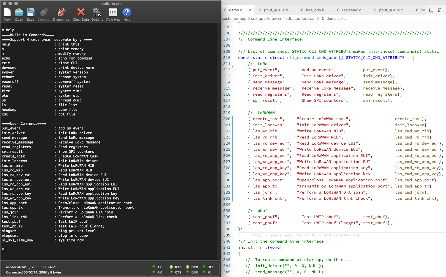
(The commands are defined in demo.c)
(The LoRaWAN commands were ported to BL602 from Apache Mynewt OS)
How will we know if our LoRaWAN Gateway has received the data packet from BL602?
If we’re running ChirpStack on our LoRaWAN Gateway, here’s how we check…
In ChirpStack, click Applications → app → device_otaa_class_a → Device Data
Restart BL602.
Run the LoRaWAN Commands from the previous section.
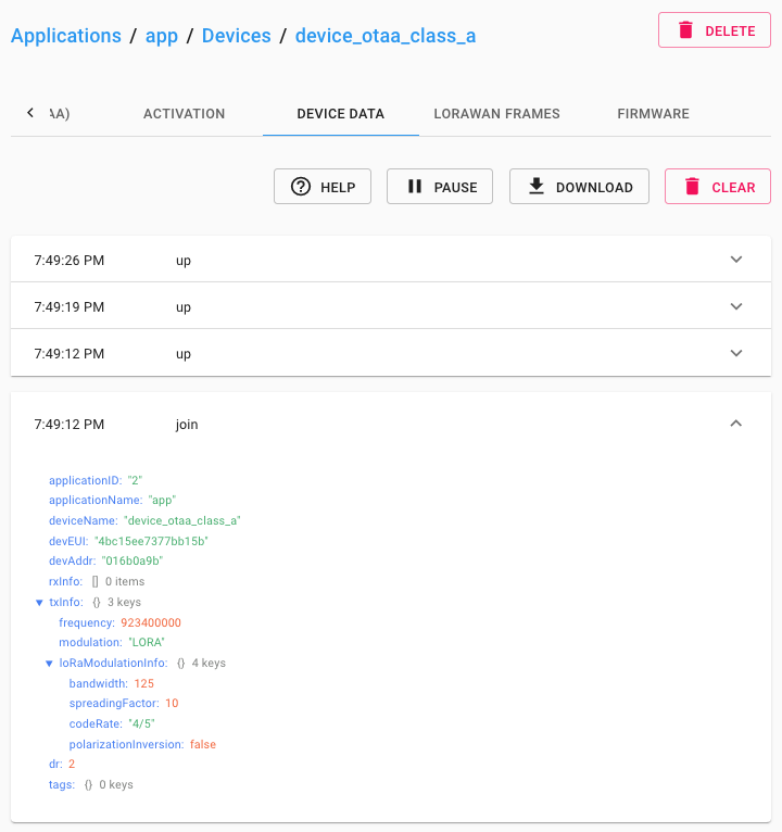
The Join Network Request appears in ChirpStack…
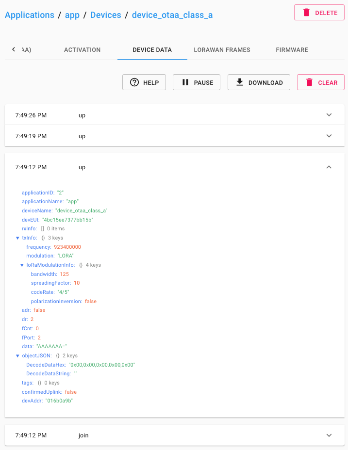
Followed by the Data Packet…
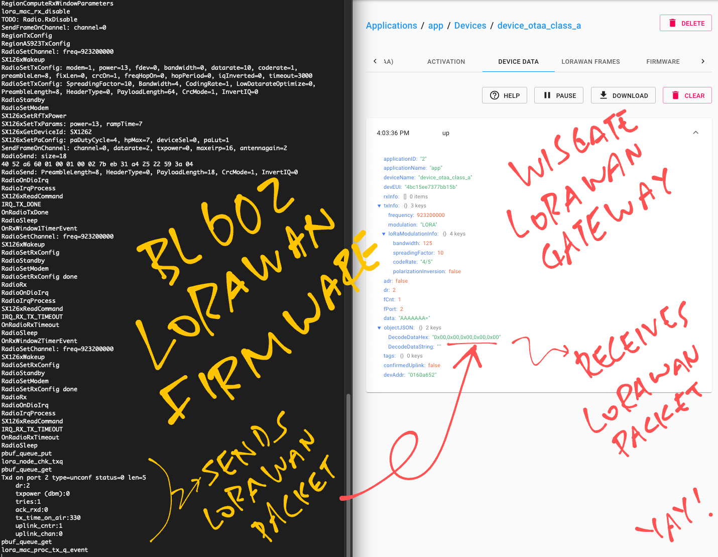
DecodedDataHex shows 5 bytes of zero, which is what we sent…
We may now configure ChirpStack to do something useful with the received packets, like publish them over MQTT, HTTP, …
Click this link…
Then click the Menu (top left) and Integrations
If our LoRaWAN Gateway didn’t receive the data packet from BL602, here are some troubleshooting tips…
Check the LoRa Transceiver
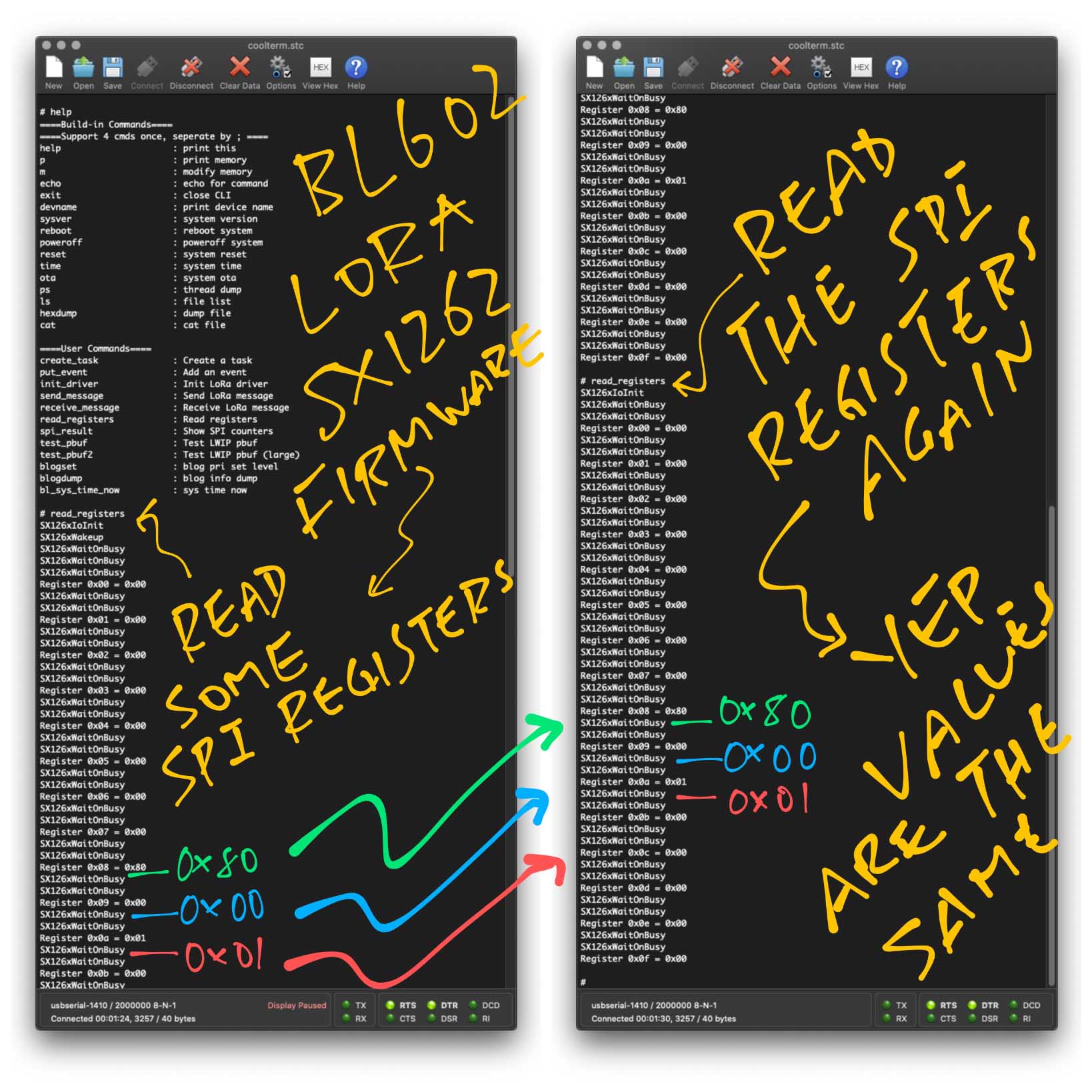
Follow the steps here to check our LoRa Transceiver…
For RFM90 / SX1262, the SPI registers should look like this…
Check the LoRaWAN Gateway logs
For ChirpStack, follow the steps here to check the LoRaWAN Gateway logs, also to inspect the raw packets…
Check the LoRa Sync Word
Typical LoRaWAN Networks will use the Public LoRa Sync Word 0x3444.
(Instead of the Private Sync Word 0x1424)
This is defined in the Makefile as…
CFLAGS += -DLORA_NODE_PUBLIC_NWK=1The LoRaWAN Gateway will not respond to our packets if we transmit the wrong Sync Word.
See the Appendix for details.
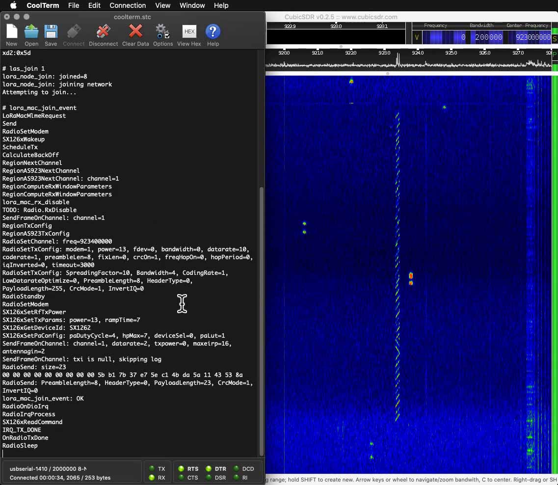
Sniff the packets with Software Defined Radio
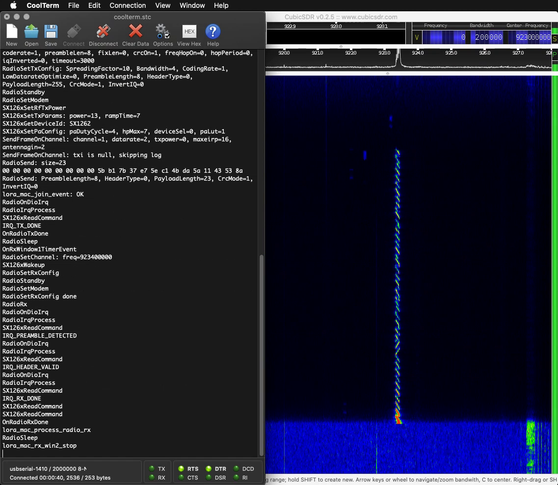
A Software Defined Radio may be helpful for sniffing the LoRaWAN packets to make sure that they look right and are centered at the right frequency…
Here’s the Join Network Request transmitted by BL602 with RFM90…
And here’s the Join Network Response returned by our WisGate D4H LoRaWAN Gateway…
Watch the demo video on YouTube
(Yep BL602 + RFM90 seems to be transmitting packets with lower power than our WisGate LoRaWAN Gateway. More about this in the Appendix.)
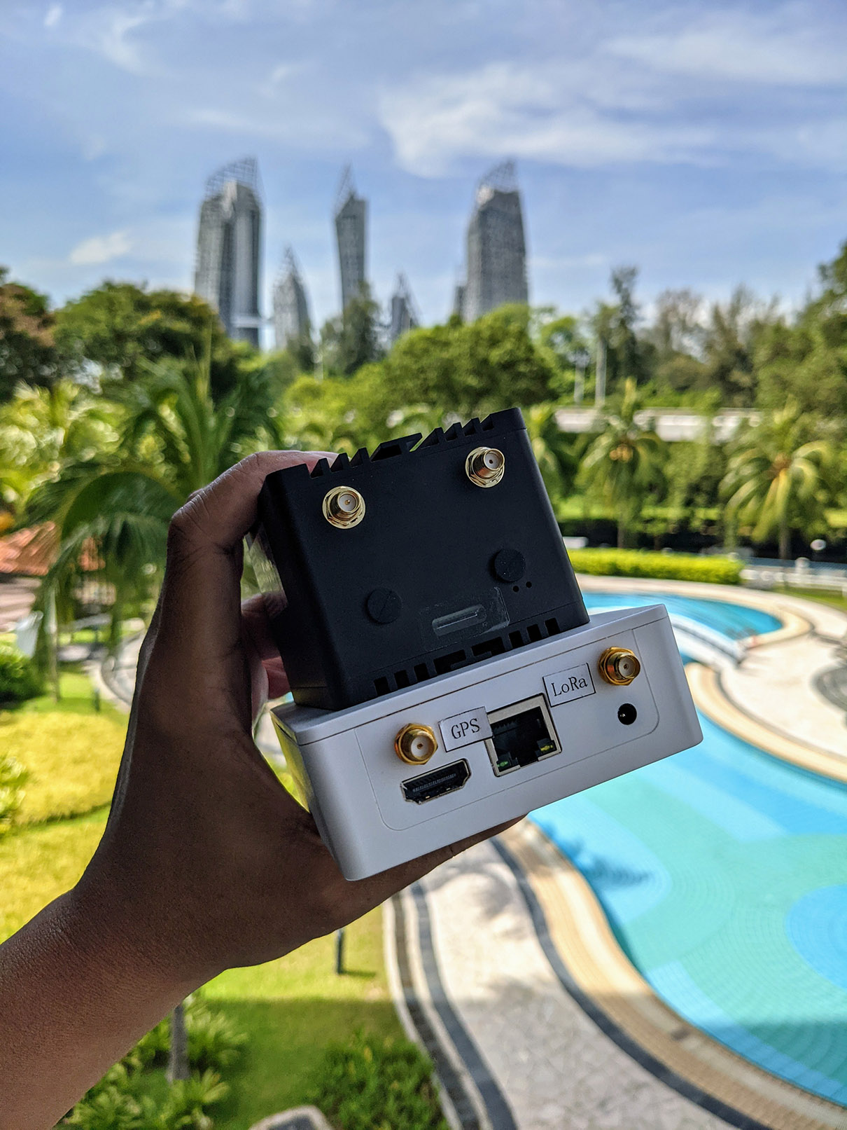
Pine64 LoRa Gateway (the white box) and RAKwireless WisGate D4H LoRaWAN Gateway (the black box)
Today we have completed Levels One and Two of our epic quest for the Three Levels of LoRa!
We have a BL602 LoRa Transceiver Driver (RFM90 / SX1262) that can transmit and receive LoRa Packets
We have a BL602 LoRaWAN Driver that can join a LoRaWAN Network and transmit LoRaWAN Data Packets
Soon we shall progress to LoRa Level Three…
Join BL602 to The Things Network!
And eventually we shall build BL602 Sensor Devices for The Things Network!
But first we shall…
Install ChirpStack on our pre-production Pine64 LoRa Gateway…
And test it with our BL602 LoRaWAN Driver.
(Maybe we’ll quickly benchmark Pine64 LoRa Gateway with RAKwireless WisGate D4H… Both are based on LoRa Concentators by RAKwireless!)
Take a short diversion to explore Lisp and Blockly (Scratch) on BL602…
Because it shows lots of potential for IoT Education.
(My #1 passion)
We have come a loooong way since I first experimented with LoRa in 2016…
Modern Transceivers and Gateways: Pine64 RFM90, Pine64 LoRa Gateway
Mature Networks: LoRaWAN, The Things Network
Better Drivers: Thanks to Apache Mynewt OS!
Powerful Microcontrollers: Arduino Uno vs RISC-V BL602
Awesome Tools: RAKwireless WisBlock, Airspy SDR, RF Explorer
Now is the right time to build LoRa gadgets. Stay tuned for more LoRa and LoRaWAN Adventures!
Meanwhile there’s plenty more code in the BL602 IoT SDK to be deciphered and documented: ADC, DAC, WiFi, Bluetooth LE, …
Come Join Us… Make BL602 Better!
🙏 👍 😀
Got a question, comment or suggestion? Create an Issue or submit a Pull Request here…
lupyuen.github.io/src/lorawan.md
This article is the expanded version of the Twitter Threads…
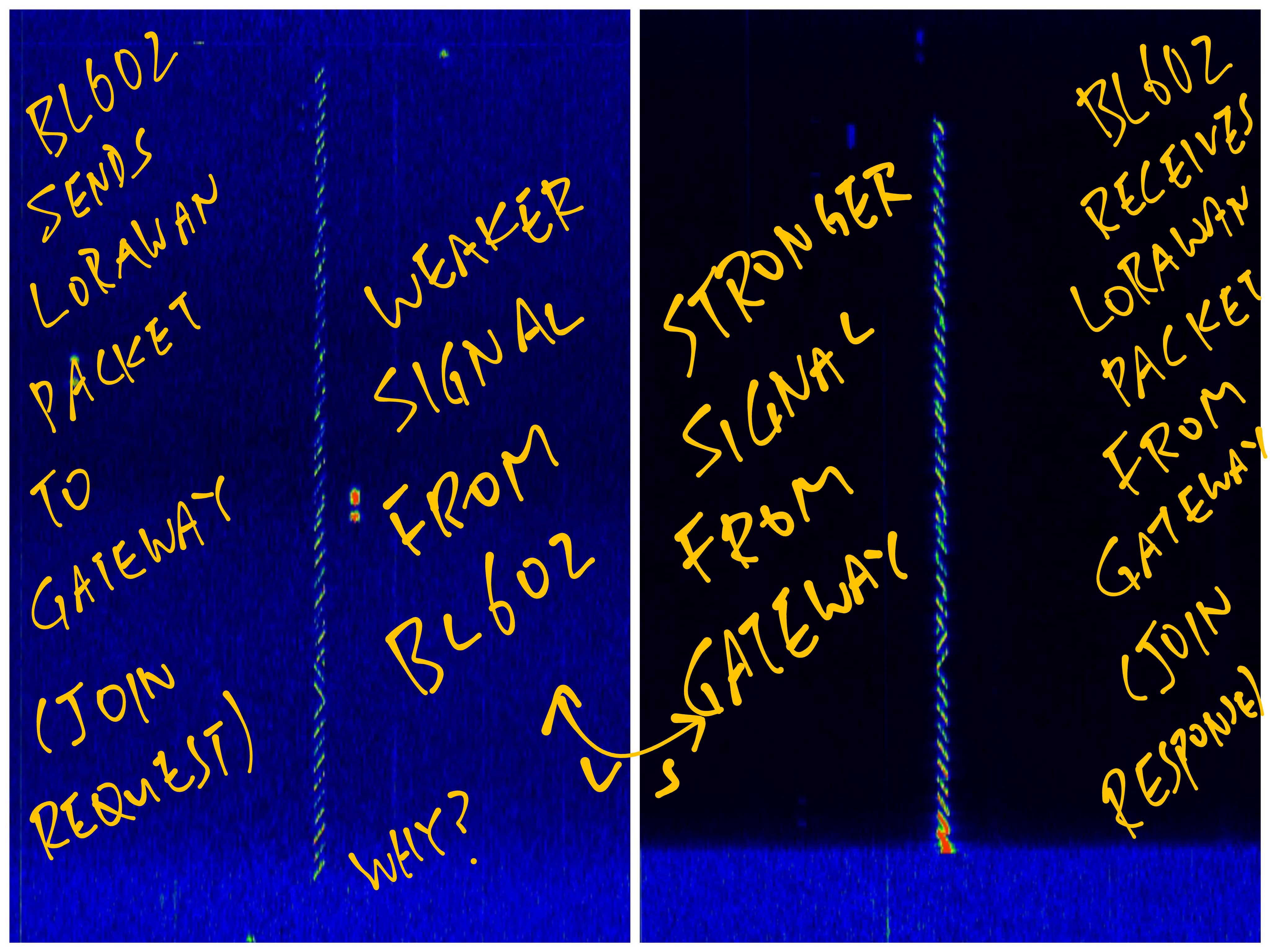
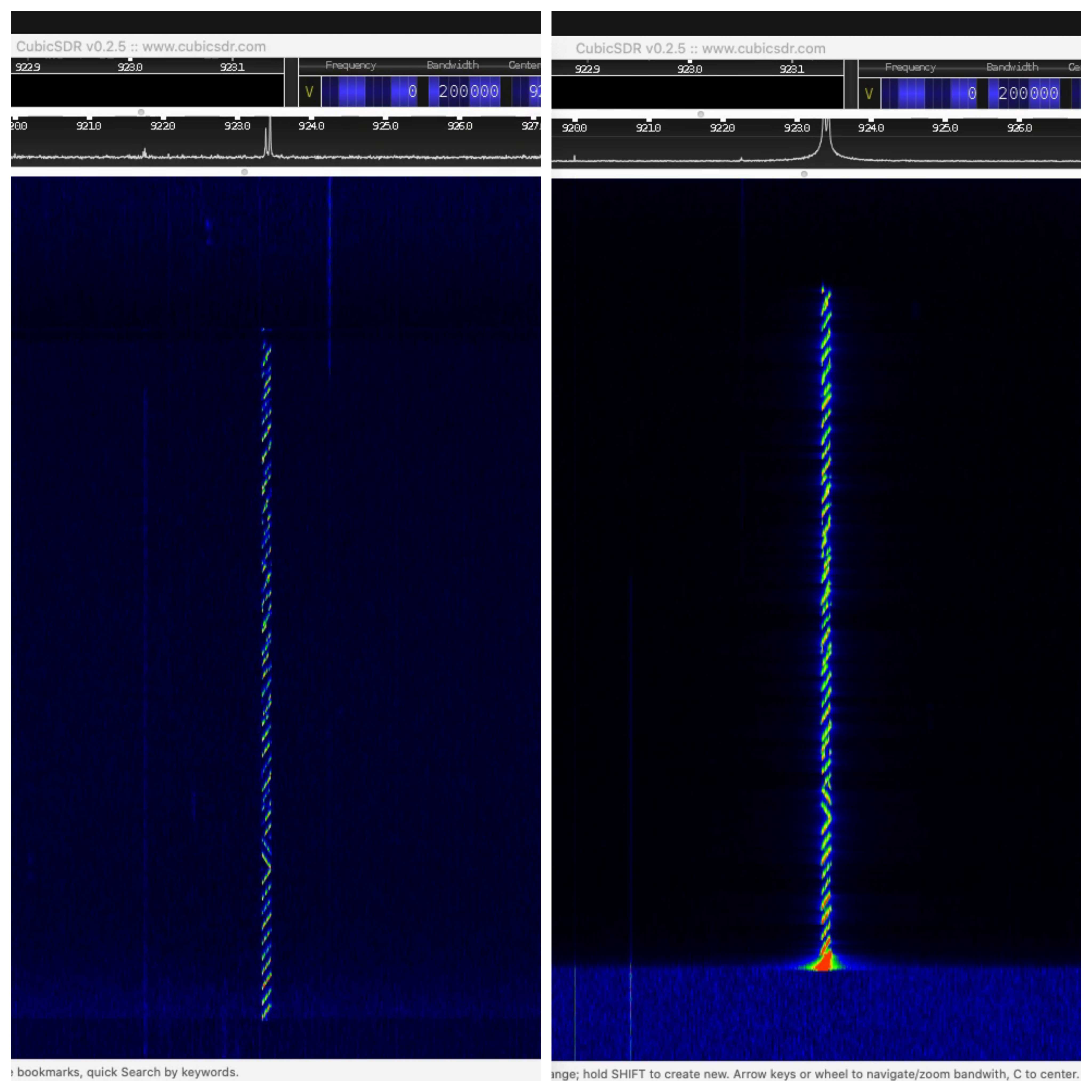
Our PineCone BL602 connected to Pine64 RFM90 LoRa Module seems to be transmitting with lower power compared with other devices… Perhaps someone could help to fix this issue. (Hardware or Firmware?)
Here’s RFM90 (left) compared with WisGate D4H LoRaWAN Gateway (right)…
Watch the demo video on YouTube
(Recorded by Airspy R2 SDR with CubicSDR. The SDR was placed near RFM90.)
And here’s RFM90 (left) compared with WisBlock RAK4631 (which is also based on Semtech SX1262)…
I might have connected the RFM90 pins incorrectly. The Semtech docs refer to DC-DC vs LDO Regulator Options, which I don’t quite understand…
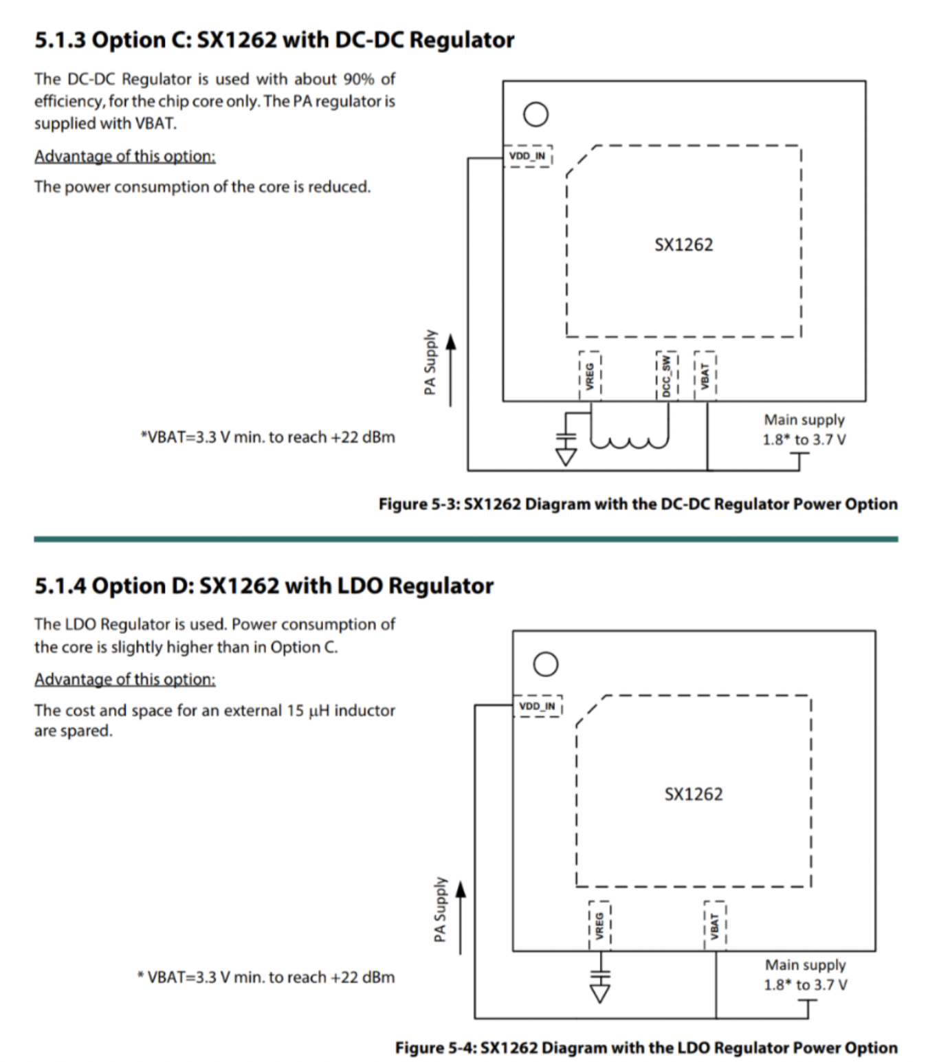
Our RFM90 / SX1262 LoRa Transceiver Driver is currently set to DC-DC Power Regulator Mode: radio.c
//  TODO: Declare the power regulation used to power the device
//  This command allows the user to specify if DC-DC or LDO is used for power regulation.
//  Using only LDO implies that the Rx or Tx current is doubled

// #warning SX126x is set to LDO power regulator mode (instead of DC-DC)
// SX126xSetRegulatorMode( USE_LDO );   //  Use LDO

#warning SX126x is set to DC-DC power regulator mode (instead of LDO)
SX126xSetRegulatorMode( USE_DCDC );  //  Use DC-DC
(Check out this discussion on Twitter)
I have increased the Transmit Power to max 22 dBm. Also I have increased the Power Amplifier Ramp Up Time from 200 to the max 3,400 microseconds: radio.c
//  Previously: SX126xSetTxParams( 0, RADIO_RAMP_200_US );
SX126xSetTxParams( 22, RADIO_RAMP_3400_US );
According to the log, the Power Amplifier seems to be enabled at the max settings: README.md
SX126xSetPaConfig:
paDutyCycle=4,
hpMax=7,
deviceSel=0,
paLut=1 I copied this Over Current Protection setting from WisBlock RAK4631 (which is also based on Semtech SX1262): sx126x.c
//  TODO: Set the current max value in the over current protection.
//  From SX126x-Arduino/src/radio/sx126x/sx126x.cpp
SX126xWriteRegister(REG_OCP, 0x38); // current max 160mA for the whole device
None of these changes seem to increase the RFM90 Transmit Power.
Would be great if you could suggest a fix for this 🙏
(Or perhaps the Transmit Power isn’t an issue?)
Typical LoRaWAN Networks will use the Public LoRa Sync Word 0x3444.
(Instead of the Private Sync Word 0x1424)
The LoRaWAN Gateway will not respond to our packets if we transmit the wrong Sync Word.
LORA_NODE_PUBLIC_NWK should be set to 1 in the Makefile …
# Sets public or private lora network. A value of 1 means
# the network is public; private otherwise.
# Must be set to 1 so that ChirpStack will detect our Public Sync Word (0x3444)
CFLAGS += -DLORA_NODE_PUBLIC_NWK=1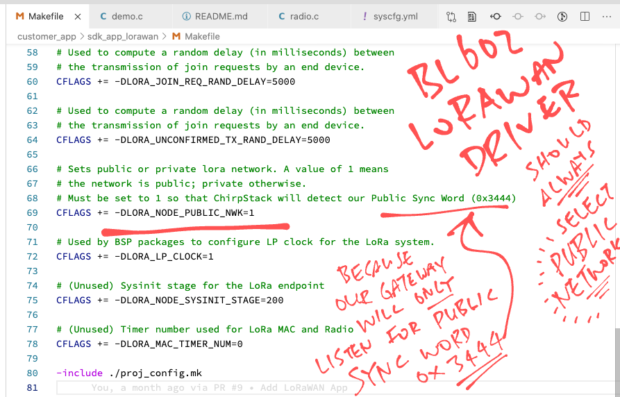
LORA_NODE_PUBLIC_NWK sets the Sync Word in LoRaMac.c …
//  Syncword for Private LoRa networks
#define LORA_MAC_PRIVATE_SYNCWORD                   0x1424

//  Syncword for Public LoRa networks
#define LORA_MAC_PUBLIC_SYNCWORD                    0x3444

//  Init the LoRaWAN Medium Access Control Layer
LoRaMacStatus_t LoRaMacInitialization(LoRaMacCallback_t *callbacks, LoRaMacRegion_t region) {
    ...
#if (LORA_NODE_PUBLIC_NWK)
    LM_F_IS_PUBLIC_NWK() = 1;
    Radio.SetPublicNetwork(true);
#else
    LM_F_IS_PUBLIC_NWK() = 0;
    Radio.SetPublicNetwork(false);
#endif
It took me a while to troubleshoot this problem: “Why is the LoRaWAN Gateway ignoring my packets?”
Till I got inspired by this quote from the Semtech SX1302 LoRa Concentrator HAL User Manual
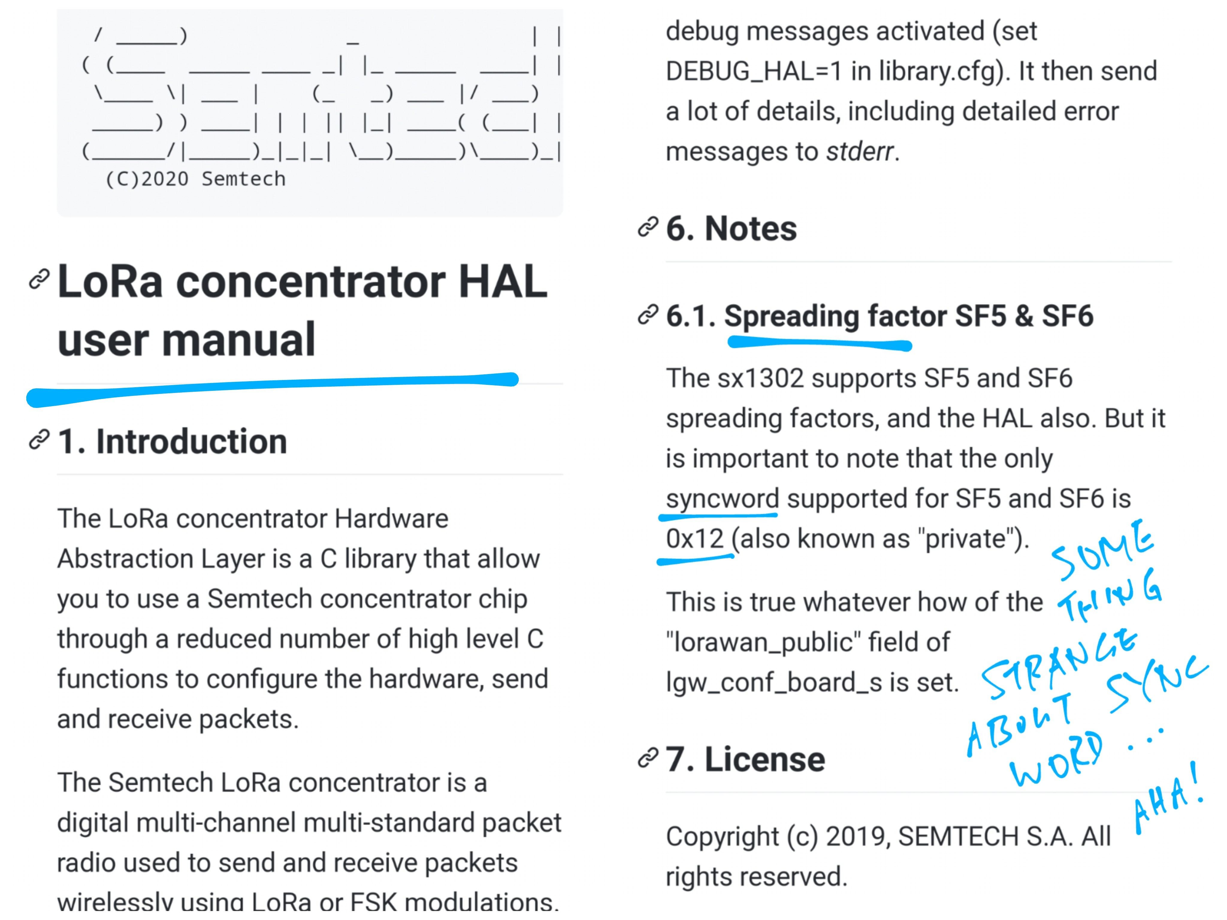
While troubleshooting the BL602 LoRaWAN Driver I compared 3 implementations of the LoRaWAN Stack…
(Dated 2017) This is the version that I ported to BL602.
(Dated 2013) This is the Arduino version used by RAKwireless WisBlock RAK4631.
It looks similar to the Mynewt version.
Semtech Reference Implementation of LoRaWAN Stack
(Dated 2021) This is official, latest version of the LoRaWAN Stack.
However it looks totally different from the other two stacks.
(Why didn’t I port this stack to BL602? Because I wasn’t sure if it would run on FreeRTOS without Event Queues and Background Tasks.)
When comparing the 3 stacks I discovered that they implement LoRa Carrier Sensing differently.
What is LoRa Carrier Sensing?
In some LoRa Regions (Japan and South Korea), devices are required (by local regulation) to sense whether the Radio Channel is in use before transmitting.
Here’s the Carrier Sensing logic from the Mynewt LoRaWAN Stack: RegionAS923.c
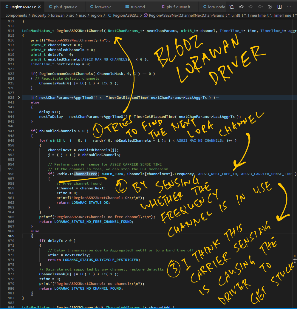
(Compare this with Semtech’s Reference Implementation)
(SX126x-Arduino skips Carrier Sensing for Japan)
But you’re in Sunny Singapore, no?
Yes, but Mynewt’s version of the LoRaWAN Stack (from 2017) applies Carrier Sensing across the entire LoRa AS923 Region, which includes Singapore…
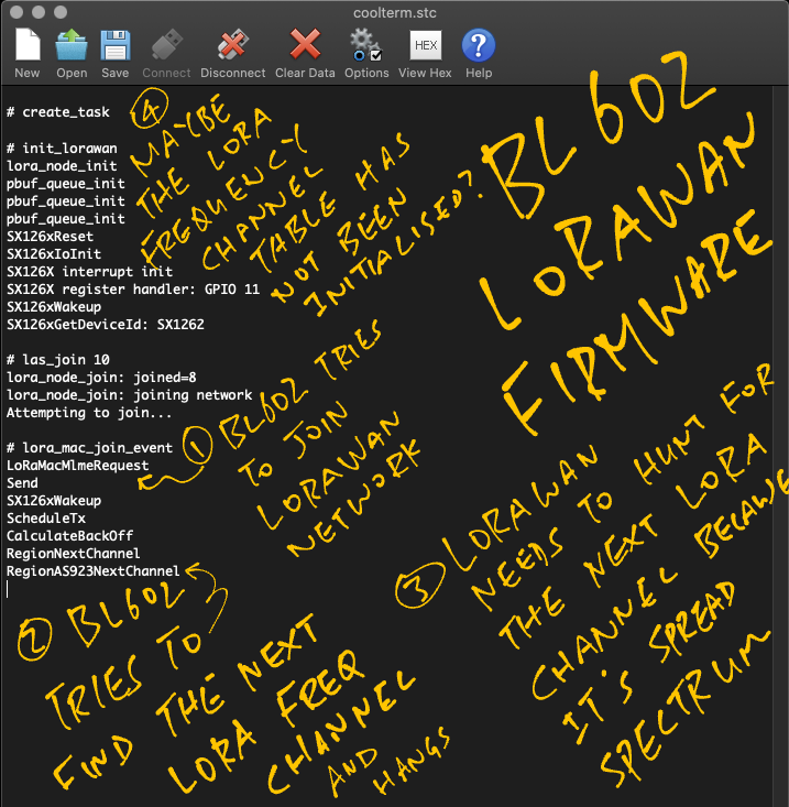
Unfortunately the Carrier Sensing code doesn’t work, so Carrier Sensing has been disabled in the BL602 LoRaWAN Driver. (See this)
(My apologies to BL602 Fans in Japan and South Korea, we will have to fix this 🙏)
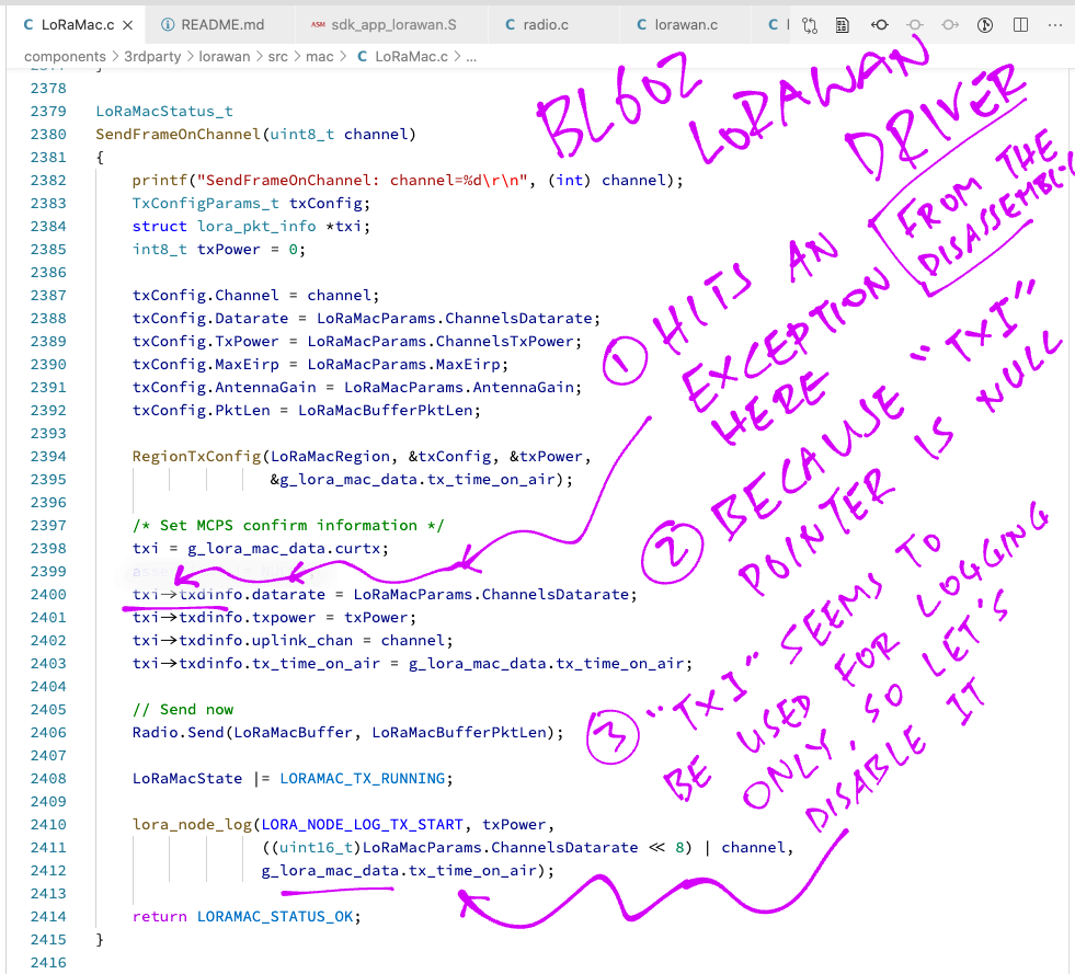
After disabling the Carrier Sensing I hit a RISC-V Exception…
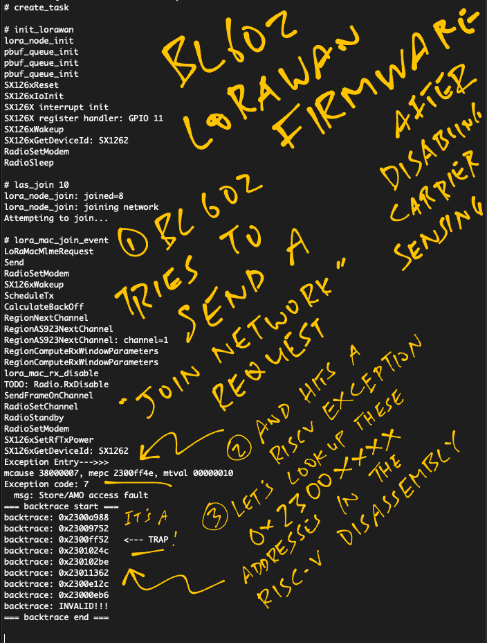
Which I traced (via the RISC-V Disassembly) to a Null Pointer problem in LoRaMac.c …
Anything else we should note?
The LoRa Region Settings seem to have major differences across the 3 LoRaWAN Stacks. We will have to patch Semtech’s latest version into BL602.
Check out the LoRa Region Settings for AS923 across the 3 LoRaWAN Stacks…
The LoRaWAN Driver from Apache Mynewt OS uses Mbufs and Mbuf Queues to manage packets efficiently. (More about this)
Here’s how we ported Mbufs and Mbuf Queues to BL602.
Mbufs are not available on BL602, but we have something similar: pbuf Packet Buffer from Lightweight IP Stack (LWIP)
Stored inside a pbuf Packet Buffer are…
Packet Header: Variable size, up to a limit (max 182 bytes)
Packet Payload: Fixed size

Here’s how we fetch the LoRaWAN Packet Header from a LoRaWAN Packet…
//  Get the LoRaWAN Packet Header
header = get_pbuf_header(
    pb,                           //  LoRaWAN Packet Buffer
    sizeof(struct lora_pkt_info)  //  Size of LoRaWAN Packet Header
);
pbuf Packet Buffers have an unusual Sliding Payload Pointer for extracting the header.
Here’s how we implement get_pbuf_header in pbuf_queue.c …
/// Return the pbuf Packet Buffer header
void *
get_pbuf_header(
    struct pbuf *buf,    //  pbuf Packet Buffer
    size_t header_size)  //  Size of header
{
    assert(buf != NULL);
    assert(header_size > 0);

    //  Warning: This code mutates the pbuf payload pointer, so we need a critical section
    //  Enter critical section
    OS_ENTER_CRITICAL(pbuf_header_mutex);

    //  Slide the pbuf payload pointer BACKWARD
    //  to locate the header.
    u8_t rc1 = pbuf_add_header(buf, header_size);

    //  Payload now points to the header
    void *header = buf->payload;

    //  Slide the pbuf payload pointer FORWARD
    //  to locate the payload.
    u8_t rc2 = pbuf_remove_header(buf, header_size);

    //  Exit critical section
    OS_EXIT_CRITICAL(pbuf_header_mutex);

    //  Check for errors
    assert(rc1 == 0);
    assert(rc2 == 0);
    assert(header != NULL);
    return header;
}
pbuf_add_header comes from the Lightweight IP Library. It slides the payload pointer backwards to point at the requested header…

(pbuf_add_header returns a non-zero error code if there’s isn’t sufficient space for the header)
Because this code mutates the Payload Pointer, we need to be extra careful when extracting the header.
Mynewt’s LoRaWAN Driver uses Mqueues to enqueue packets for processing.
The Lightweight IP Stack doesn’t have the equivalent of Mqueues, so we build our own Packet Buffer Queues.
A pbuf_queue Packet Buffer Queue is a First-In First-Out List of Packet Buffers. It supports these operations…
From pbuf_queue.c
//  Initializes a pbuf_queue.  A pbuf_queue is a queue of pbufs that ties to a
//  particular task's event queue.  pbuf_queues form a helper API around a common
//  paradigm: wait on an event queue until at least one packet is available,
//  then process a queue of packets.
int pbuf_queue_init(struct pbuf_queue *mq, ble_npl_event_fn *ev_cb, void *arg, uint16_t header_len);

//  Remove and return a single pbuf from the pbuf queue.  Does not block.
struct pbuf *pbuf_queue_get(struct pbuf_queue *mq);

//  Adds a packet (i.e. packet header pbuf) to a pbuf_queue. The event associated
//  with the pbuf_queue gets posted to the specified eventq.
int pbuf_queue_put(struct pbuf_queue *mq, struct ble_npl_eventq *evq, struct pbuf *m);
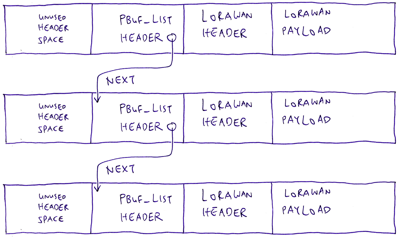
To build a Linked List of Packet Buffers, we insert a pbuf_list Header just before the LoRaWAN Header in the LoRaWAN Packet…

(Yes the Lightweight IP Stack allows multiple headers per Packet Buffer, because of the Sliding Payload Pointer)
The pbuf_list Header points to the next Packet Buffer in the Singly-Linked List…
From pbuf_queue.h
//  Structure representing a list of pbufs inside a pbuf_queue.
//  pbuf_list is stored in the header of the pbuf, before the LoRaWAN Header.
struct pbuf_list {
    //  Header length
    u16_t header_len;
    //  Payload length
    u16_t payload_len;
    //  Pointer to pbuf
    struct pbuf *pb;
    //  Pointer to header in pbuf
    struct pbuf *header;
    //  Pointer to payload in pbuf
    struct pbuf *payload;
    //  Pointer to next node in the pbuf_list
    STAILQ_ENTRY(pbuf_list) next;
    //  STAILQ_ENTRY is defined in https://github.com/lupyuen/lorawan/blob/main/include/node/bsd_queue.h
};
The next field lets us link up the Packet Buffers like so…
Here’s how we allocate a Packet Buffer and initialise both headers: pbuf_list Header and LoRaWAN Header…
From pbuf_queue.c
/// Allocate a pbuf for LoRaWAN transmission. This returns a pbuf with
/// pbuf_list Header, LoRaWAN Header and LoRaWAN Payload.
struct pbuf *
alloc_pbuf(
    uint16_t header_len,   //  Header length of packet (LoRaWAN Header only, excluding pbuf_list header)
    uint16_t payload_len)  //  Payload length of packet, excluding header
{
    //  Init LWIP Buffer Pool
    static bool lwip_started = false;
    if (!lwip_started) {
        lwip_started = true;
        lwip_init();
    }

    //  Allocate a pbuf Packet Buffer with sufficient header space for pbuf_list header and LoRaWAN header
    struct pbuf *buf = pbuf_alloc(
        PBUF_TRANSPORT,   //  Buffer will include 182-byte transport header
        payload_len,      //  Payload size
        PBUF_RAM          //  Allocate as a single block of RAM
    );                    //  TODO: Switch to pooled memory (PBUF_POOL), which is more efficient
    assert(buf != NULL);

    //  Erase packet
    memset(buf->payload, 0, payload_len);

    //  Packet Header will contain two structs: pbuf_list Header, followed by LoRaWAN Header
    size_t combined_header_len = sizeof(struct pbuf_list) + header_len;

    //  Get pointer to pbuf_list Header and LoRaWAN Header
    void *combined_header = get_pbuf_header(buf, combined_header_len);
    void *header          = get_pbuf_header(buf, header_len);
    assert(combined_header != NULL);
    assert(header != NULL);

    //  Erase pbuf_list Header and LoRaWAN Header
    memset(combined_header, 0, combined_header_len);

    //  Init pbuf_list header at the start of the combined header
    struct pbuf_list *list = combined_header;
    list->header_len  = header_len;
    list->payload_len = payload_len;
    list->header      = header;
    list->payload     = buf->payload;
    list->pb          = buf;

    //  Verify integrity of pbuf_list: pbuf_list Header is followed by LoRaWAN Header and LoRaWAN Payload
    assert((uint32_t) list + sizeof(struct pbuf_list) + list->header_len == (uint32_t) list->payload);
    assert((uint32_t) list + sizeof(struct pbuf_list) == (uint32_t) list->header);
    assert((uint32_t) list->header + list->header_len == (uint32_t) list->payload);

    return buf;
}Here’s how our LoRa Transceiver Driver initialises the BL602 SPI Port by calling the BL602 SPI Hardware Abstraction Layer (HAL)…
From sx126x-board.c
/// SPI Device Instance
spi_dev_t spi_device;

/// Initialise GPIO Pins and SPI Port. Called by SX126xIoIrqInit.
/// Note: This is different from the Reference Implementation,
/// which initialises the GPIO Pins and SPI Port at startup.
void SX126xIoInit( void ) {
    GpioInitOutput( SX126X_SPI_CS_PIN, 1 );
    GpioInitInput( SX126X_BUSY_PIN, 0, 0 );
    GpioInitInput( SX126X_DIO1, 0, 0 );

    //  Configure the SPI Port
    int rc = spi_init(
        &spi_device,     //  SPI Device
        SX126X_SPI_IDX,  //  SPI Port
        0,               //  SPI Mode: 0 for Controller
        //  TODO: Due to a quirk in BL602 SPI, we must set
        //  SPI Polarity-Phase to 1 (CPOL=0, CPHA=1).
        //  But actually Polarity-Phase for SX126X should be 0 (CPOL=0, CPHA=0).
        1,                    //  SPI Polarity-Phase
        SX126X_SPI_BAUDRATE,  //  SPI Frequency
        2,                    //  Transmit DMA Channel
        3,                    //  Receive DMA Channel
        SX126X_SPI_CLK_PIN,   //  SPI Clock Pin
        SX126X_SPI_CS_OLD,    //  Unused SPI Chip Select Pin
        SX126X_SPI_SDI_PIN,   //  SPI Serial Data In Pin  (formerly MISO)
        SX126X_SPI_SDO_PIN    //  SPI Serial Data Out Pin (formerly MOSI)
    );
    assert(rc == 0);
}
(The pins are defined in sx126x-board.h)
The BL602 SPI HAL is explained in the article…
Note that the SPI Polarity-Phase has been modified. (More about this)
Here’s how our LoRa Transceiver Driver calls the BL602 SPI HAL to transmit and receive a single byte to RFM90 / SX1262…
From sx126x-board.c
/// SPI Transmit Buffer (1 byte)
static uint8_t spi_tx_buf[1];

/// SPI Receive Buffer (1 byte)
static uint8_t spi_rx_buf[1];

/// Blocking call to send a value on the SPI. Returns the value received from the SPI Peripheral.
/// Assume that we are sending and receiving 8-bit values on SPI.
/// Assume Chip Select Pin has already been set to Low by caller.
/// TODO: We should combine multiple SPI DMA Requests, instead of handling one byte at a time
uint16_t SpiInOut(int spi_num, uint16_t val) {
    //  Populate the transmit buffer
    spi_tx_buf[0] = val;

    //  Clear the receive buffer
    memset(&spi_rx_buf, 0, sizeof(spi_rx_buf));

    //  Prepare SPI Transfer
    static spi_ioc_transfer_t transfer;
    memset(&transfer, 0, sizeof(transfer));
    transfer.tx_buf = (uint32_t) spi_tx_buf;  //  Transmit Buffer
    transfer.rx_buf = (uint32_t) spi_rx_buf;  //  Receive Buffer
    transfer.len    = 1;                      //  How many bytes

    //  Assume Chip Select Pin has already been set to Low by caller

    //  Execute the SPI Transfer with the DMA Controller
    int rc = hal_spi_transfer(
        &spi_device,  //  SPI Device
        &transfer,    //  SPI Transfers
        1             //  How many transfers (Number of requests, not bytes)
    );
    assert(rc == 0);

    //  Assume Chip Select Pin will be set to High by caller

    //  Return the received byte
    return spi_rx_buf[0];
}The LoRa Transceiver (RFM90 / SX1262) triggers a GPIO Interrupt on BL602 when it receives a LoRa Packet…

Our LoRa Transceiver Driver handles this GPIO Interrupt by registering a GPIO Interrupt Handler like so: radio.c
/// Init the LoRa Transceiver
void RadioInit( RadioEvents_t *events ) {
    ...
    SX126xInit( RadioOnDioIrq );
RadioOnDioIrq is the function that will handle the GPIO Interrupt. (See this)
SX126xInit is defined in sx126x.c …
/// Init the SX1262 LoRa Transceiver
void SX126xInit( DioIrqHandler dioIrq ) {
    ...
    //  dioIrq is the GPIO Handler Function RadioOnDioIrq
    SX126xIoIrqInit( dioIrq );
We call SX126xIoIrqInit to set RadioOnDioIrq as the GPIO Handler Function: sx126x-board.c
/// Initialise GPIO Pins and SPI Port. Register GPIO Interrupt Handler for DIO1.
/// Based on hal_button_register_handler_with_dts in https://github.com/lupyuen/bl_iot_sdk/blob/master/components/hal_drv/bl602_hal/hal_button.c
/// Note: This is different from the Reference Implementation,
/// which initialises the GPIO Pins and SPI Port at startup.
void SX126xIoIrqInit( DioIrqHandler dioIrq ) {
    //  Initialise GPIO Pins and SPI Port.
    //  Note: This is different from the Reference Implementation,
    //  which initialises the GPIO Pins and SPI Port at startup.
    SX126xIoInit();

    assert(SX126X_DIO1 >= 0);
    assert(dioIrq != NULL);
    int rc = register_gpio_handler(   //  Register GPIO Handler...
        SX126X_DIO1,                  //  GPIO Pin Number
        dioIrq,                       //  GPIO Handler Function: RadioOnDioIrq
        GLB_GPIO_INT_CONTROL_ASYNC,   //  Async Control Mode
        GLB_GPIO_INT_TRIG_POS_PULSE,  //  Trigger when GPIO level shifts from Low to High
        0,                            //  No pullup
        0                             //  No pulldown
    );
    assert(rc == 0);

    //  Register Common Interrupt Handler for GPIO Interrupt
    bl_irq_register_with_ctx(
        GPIO_INT0_IRQn,         //  GPIO Interrupt
        handle_gpio_interrupt,  //  Interrupt Handler
        NULL                    //  Argument for Interrupt Handler
    );

    //  Enable GPIO Interrupt
    bl_irq_enable(GPIO_INT0_IRQn);
}(RadioOnDioIrq is explained here)
This code is explained here…
For safety we don’t call RadioOnDioIrq directly from the Interrupt Context.
Instead we forward the GPIO Interrupt to an Event Queue…

A FreeRTOS Background Task will execute RadioOnDioIrq in the Application Context, where it’s safe to call SPI Functions, printf and other nice things.
This is explained here…