📝 4 Apr 2021
Not too long ago (and not so far away) we embarked on an epic quest to create a low-power, long-range LoRa IoT Sensor with PineCone BL602 RISC-V Board
We created a LoRa Transmitter with BL602…
Then we tested it with a LoRa Receiver: RAKwireless WisBlock…
“RAKwireless WisBlock talks LoRa with PineCone BL602 RISC-V Board”
Today we shall create the LoRa Firmware for BL602 that will Receive LoRa Packets. And test it with RAKwireless WisBlock as the LoRa Transmitter.
Why do we need to receive LoRa Packets… If our BL602 LoRa Sensor will only transmit sensor data?
Because we’ll soon connect our BL602 LoRa Sensor to a secure, managed LoRaWAN Network like The Things Network. (Or maybe Helium)
Our BL602 gadget can’t join these networks unless it can receive packets and respond to the network.
Let’s make it so! (Because we do… Or do not… There is no try!)
The LoRa Firmware in this article will run on PineCone, Pinenut and Any BL602 Board.
UPDATE: We have a new LoRa Driver for SX1262 (Pine64 RFM90 LoRa Module)… Check this out
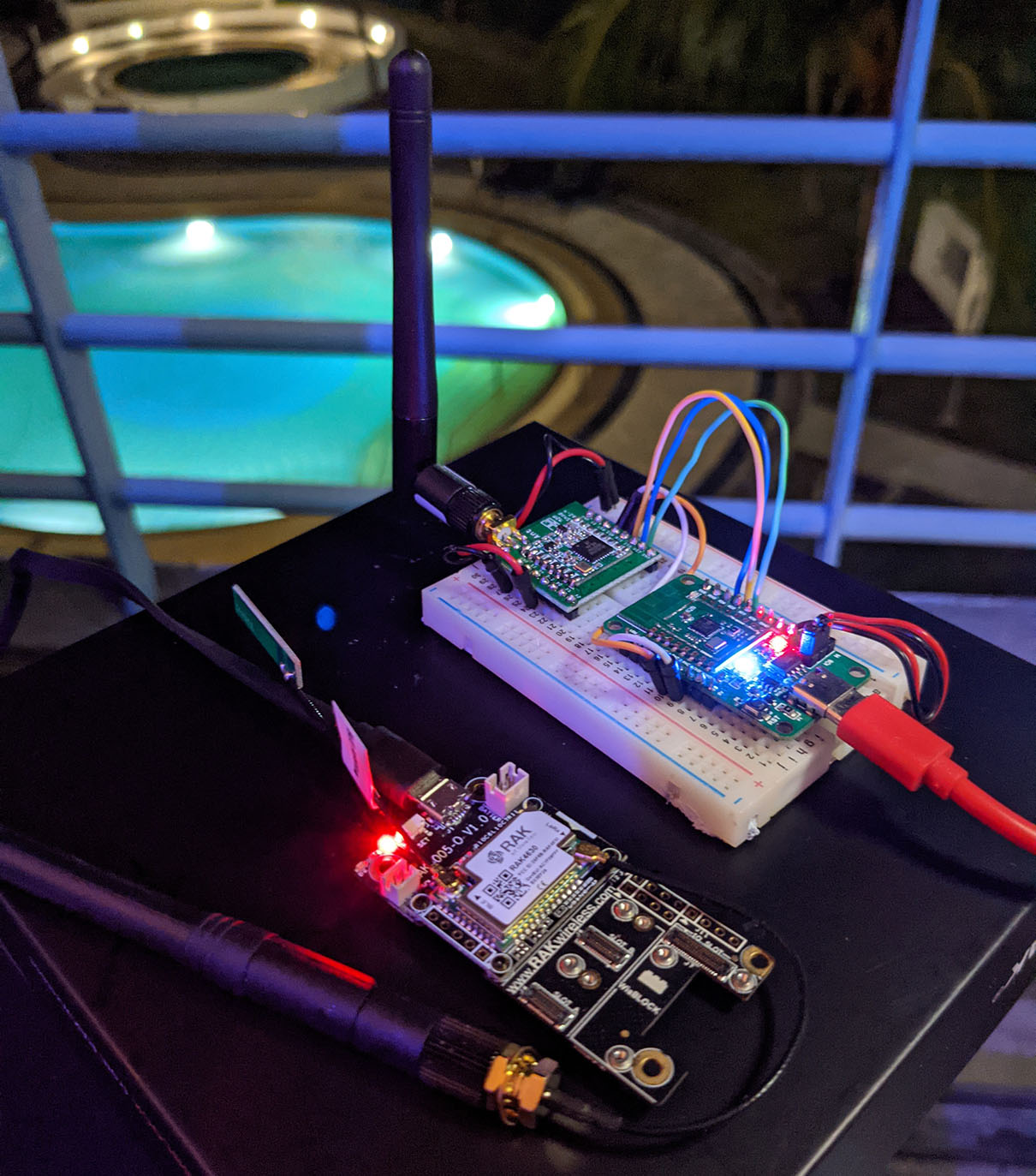
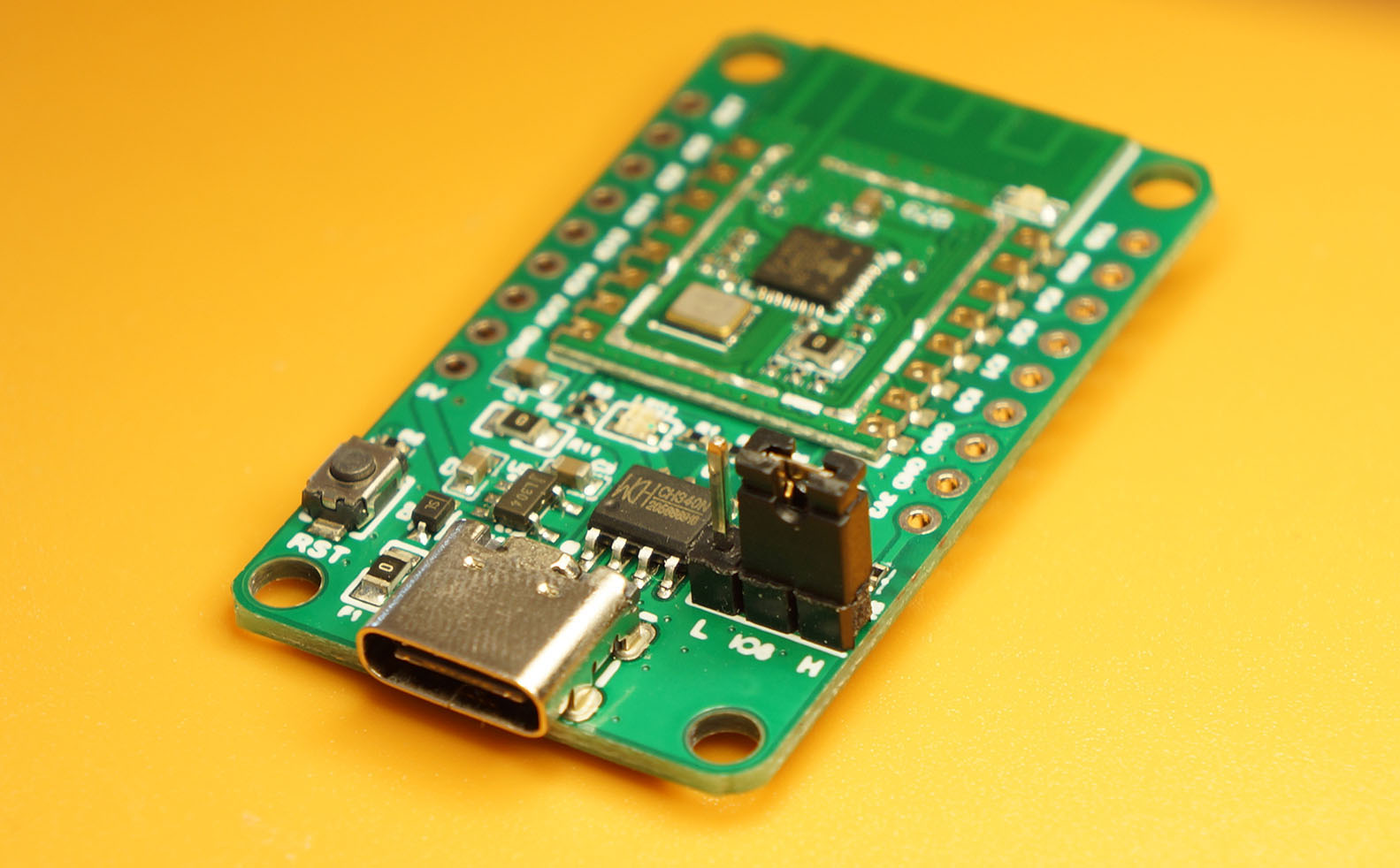
PineCone BL602 RISC-V Board with Hope RF96 LoRa Transceiver (top) receives LoRa packets from RAKwireless WisBlock (bottom)
Connect BL602 to Semtech SX1276 or Hope RF96 as follows…
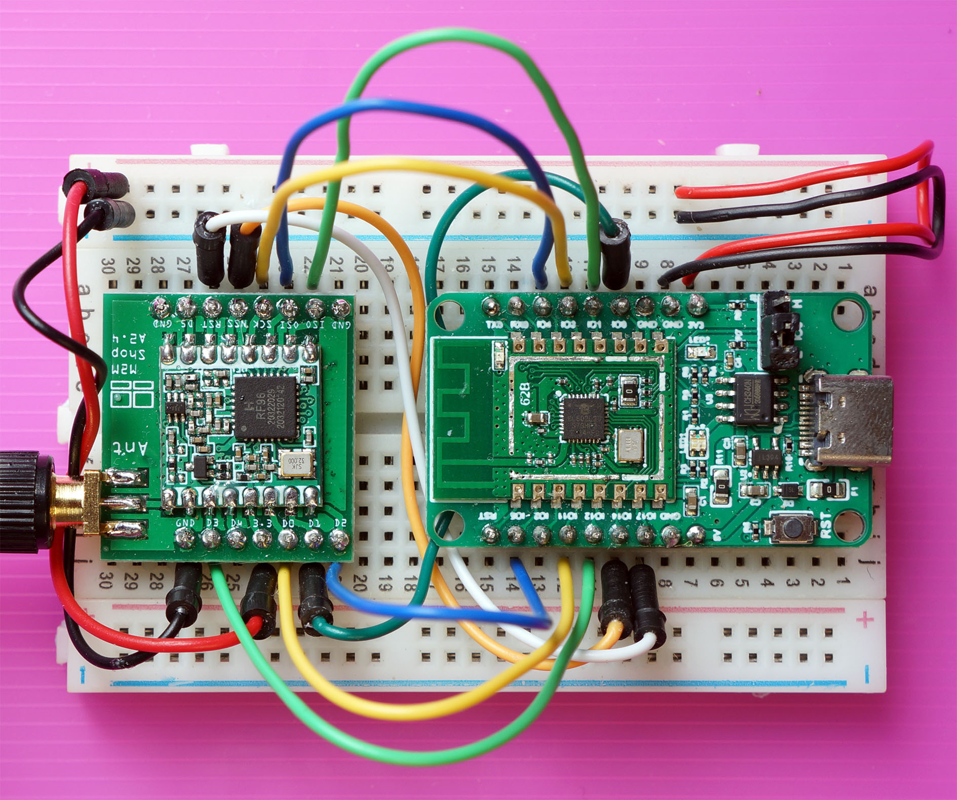
| BL602 Pin | SX1276 / RF96 Pin | Wire Colour |
|---|---|---|
GPIO 0 | DIO1 | Dark Green |
GPIO 1 | ISO (MISO) | Light Green (Top) |
GPIO 2 | Do Not Connect | (Unused Chip Select) |
GPIO 3 | SCK | Yellow (Top) |
GPIO 4 | OSI (MOSI) | Blue (Top) |
GPIO 5 | DIO2 | Blue (Bottom) |
GPIO 11 | DIO0 | Yellow (Bottom) |
GPIO 12 | DIO3 | Light Green (Bottom) |
GPIO 14 | NSS | Orange |
GPIO 17 | RST | White |
3V3 | 3.3V | Red |
GND | GND | Black |
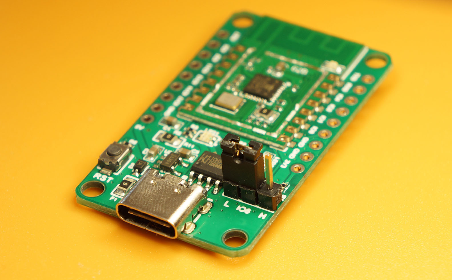
Here’s a closer look at the pins connected on BL602…
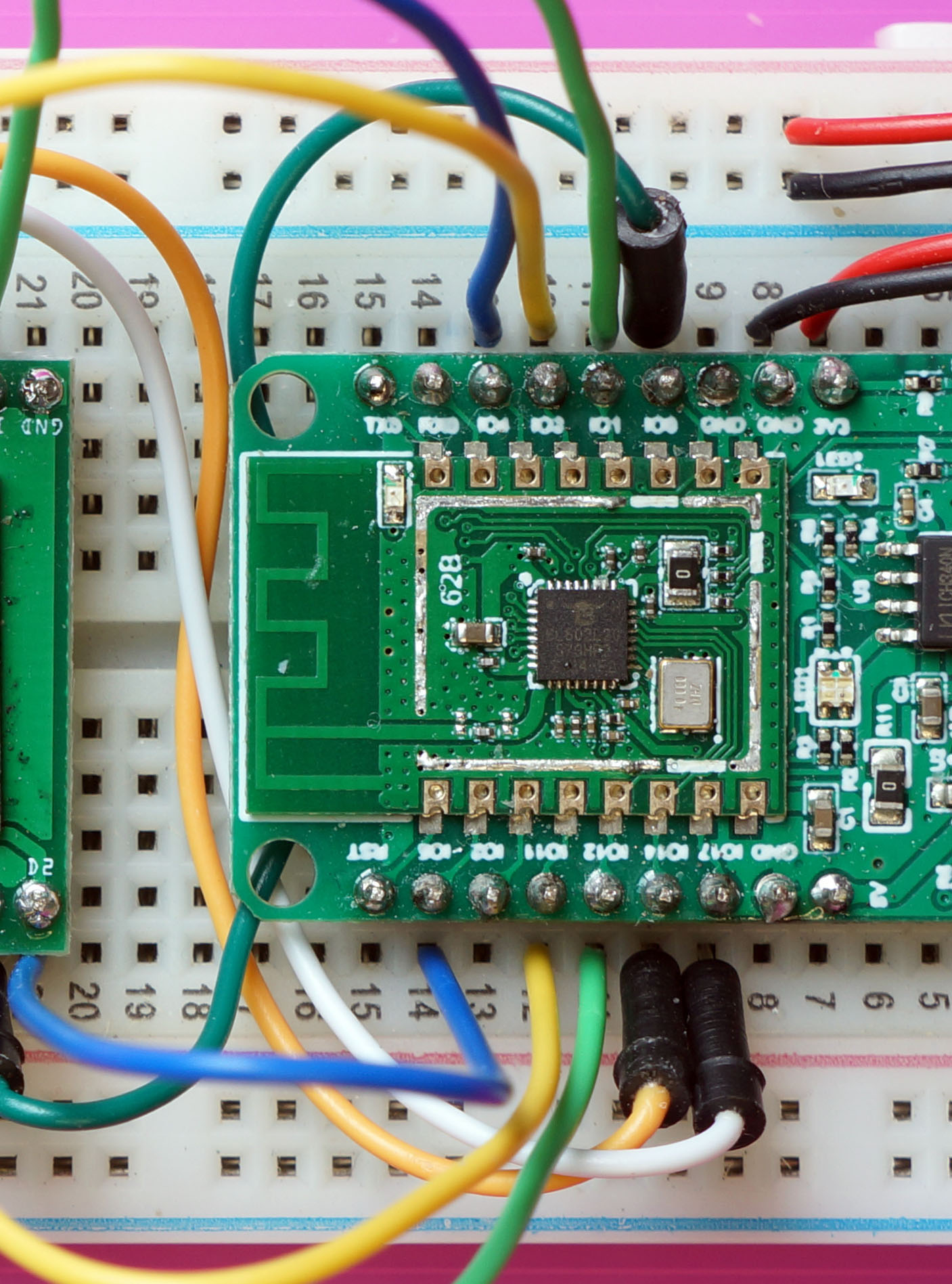
Why is BL602 Pin 2 unused?
GPIO 2 is the Unused SPI Chip Select on BL602.
We won’t use this pin because we’ll control Chip Select ourselves on GPIO 14. (See this)
Here are the pins connected on our LoRa Transceiver: SX1276 or RF96…
(ISO and OSI appear flipped in this pic… Rotate your phone / computer screen 180 degrees for the proper perspective)
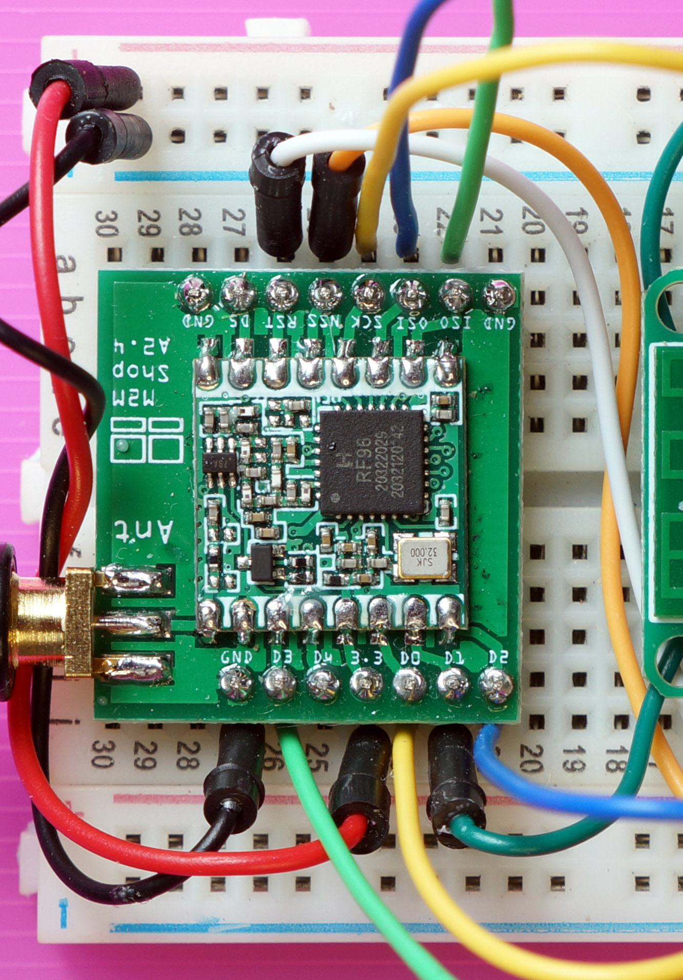
Why do we connect so many pins on SX1276 (or RF96)?
The SX1276 and RF96 transceivers have 6 (!) Digital Input / Output pins: DIO0 to DIO5
The transceiver shifts the Logic Levels of these pins from Low to High when specific conditions occur…
DIO0 Packet Received: This pin is triggered when the transceiver receives a LoRa Packet.
DIO0 is also triggered after the transceiver has transmitted a LoRa Packet, but that’s not so useful.
DIO1 Receive Timeout: This pin is triggered when the transceiver doesn’t receive any LoRa Packets within a timeout window.
This works only when the transceiver is configured for Single Receive Mode.
However today we’re configuring our transceiver for Continuous Receive Mode so we won’t be using DIO1. We shall trigger receive timeouts with a BL602 Timer.
DIO2 Change Channel: This is used for Spread Spectrum Transmission (Frequency Hopping).
When we transmit / receive LoRa Packets over multiple frequencies (spread spectrum), we reduce the likelihood of packet collisions over the airwaves.
We won’t be using Spread Spectrum Transmission today, so DIO2 shall stay idle.
DIO3 Channel Activity Detection: The transceiver lets us detect whether there’s any ongoing transmission in a LoRa Radio Channel, in a power-efficient way.
We won’t be using Channel Activity Detection today.
DIO4 and DIO5 are not connected to BL602. They are used for FSK Radio Modulation only.
(We’re using LoRa Radio Modulation)
Only 1 pin DIO0 is required for receiving simple LoRa Packets, without the frills (like Spread Spectrum Transmission).
But for now we shall connect 4 pins DIO0 to DIO3, just in case they will be needed later for LoRaWAN. (Which will probably use Spread Spectrum Transmission)
We shall configure BL602 to trigger GPIO Interrupts when the 4 pins shift from Low to High.
Let’s look at the code inside our LoRa Firmware for BL602: sdk_app_lora
Super Important: We should set the LoRa Frequency in demo.c like so…
/// TODO: We are using LoRa Frequency 923 MHz
/// for Singapore. Change this for your region.
#define USE_BAND_923
In a while we shall change 923 to the LoRa Frequency for our region: 434, 780, 868, 915 or 923 MHz. (Check this list)
For now we’ll study this function init_driver that initialises the LoRa Driver for SX1276 (and RF96) in demo.c
/// Command to initialise the SX1276 / RF96 driver
static void init_driver(char *buf, int len, int argc, char **argv) {
    //  Set the LoRa Callback Functions
    RadioEvents_t radio_events;
    memset(&radio_events, 0, sizeof(radio_events));  //  Must init radio_events to null, because radio_events lives on stack!
    radio_events.TxDone    = on_tx_done;
    radio_events.RxDone    = on_rx_done;
    radio_events.TxTimeout = on_tx_timeout;
    radio_events.RxTimeout = on_rx_timeout;
    radio_events.RxError   = on_rx_error;
init_driver begins by defining the Callback Functions that will be called when we have transmitted or received a LoRa Packet (successfully or unsuccessfully)…
Packet Transmitted: on_tx_done
Called when the transceiver has successfully transmitted a LoRa Packet.
Packet Received: on_rx_done
Called when the tranceiver has received a LoRa Packet. (More about this in a while)
Transmit Timeout: on_tx_timeout
Called if the transceiver is unable to transmit a LoRa Packet.
Receive Timeout: on_rx_timeout:
Called if the transceiver doesn’t receive any LoRa Packets within a timeout window. (More about this in a while)
Receive Error: on_rx_error:
Called if the transceiver encounters an error when receiving a LoRa Packet. (More about this in a while)
Next we call Radio.Init to initialise BL602’s SPI Port and the LoRa Transceiver…
    //  Init the SPI Port and the LoRa Transceiver
    Radio.Init(&radio_events);
Radio.Init will set some registers on our LoRa Transceiver (over SPI).
Then we call Radio.SetChannel to set the LoRa Frequency…
    //  Set the LoRa Frequency, which is specific to our region.
    //  For USE_BAND_923: RF_FREQUENCY is set to 923000000.
    Radio.SetChannel(RF_FREQUENCY);
Radio.SetChannel configures the LoRa Frequency by writing to the Frequency Registers in our LoRa Transceiver.
We get ready to transmit by calling Radio.SetTxConfig…
    //  Configure the LoRa Transceiver for transmitting messages
    Radio.SetTxConfig(
        MODEM_LORA,
        LORAPING_TX_OUTPUT_POWER,
        0,        //  Frequency deviation: Unused with LoRa
        LORAPING_BANDWIDTH,
        LORAPING_SPREADING_FACTOR,
        LORAPING_CODINGRATE,
        LORAPING_PREAMBLE_LENGTH,
        LORAPING_FIX_LENGTH_PAYLOAD_ON,
        true,     //  CRC enabled
        0,        //  Frequency hopping disabled
        0,        //  Hop period: N/A
        LORAPING_IQ_INVERSION_ON,
        LORAPING_TX_TIMEOUT_MS
    );
At the end of the function we call Radio.SetRxConfig to configure the transceiver for receiving LoRa Packets…
    //  Configure the LoRa Transceiver for receiving messages
    Radio.SetRxConfig(
        MODEM_LORA,
        LORAPING_BANDWIDTH,
        LORAPING_SPREADING_FACTOR,
        LORAPING_CODINGRATE,
        0,        //  AFC bandwidth: Unused with LoRa
        LORAPING_PREAMBLE_LENGTH,
        LORAPING_SYMBOL_TIMEOUT,
        LORAPING_FIX_LENGTH_PAYLOAD_ON,
        0,        //  Fixed payload length: N/A
        true,     //  CRC enabled
        0,        //  Frequency hopping disabled
        0,        //  Hop period: N/A
        LORAPING_IQ_INVERSION_ON,
        true      //  Continuous receive mode
    );
}
What’s Continuous Receive Mode?
Continuous Receive Mode means that the transceiver will wait forever for incoming packets… Until we tell it to stop.
(We’ll stop the transceiver with a BL602 Timer)
But before that, we need to tell the transceiver to begin receiving packets. That’s coming up next…
(The code in this article is based on the LoRa Ping program from Mynewt OS. More about this)
We’re creating a battery-powered IoT Sensor with LoRa.
To conserve battery power, we don’t listen for incoming LoRa Packets all the time… We listen for 5 seconds then go to sleep.
This is how we do it: demo.c
/// LoRa Receive Timeout in 5 seconds
#define LORAPING_RX_TIMEOUT_MS 5000  //  Milliseconds

/// Command to receive a LoRa message. Assume that SX1276 / RF96 driver has been initialised.
/// Assume that create_task has been called to init the Event Queue.
static void receive_message(char *buf, int len, int argc, char **argv) {
    //  Receive a LoRa message within 5 seconds
    Radio.Rx(LORAPING_RX_TIMEOUT_MS);
}
The receive_message command calls Radio.Rx (from the SX1276 Driver) to receive a LoRa Packet within 5 seconds.
Upon receiving the LoRa Packet, the SX1276 Driver calls the Callback Function on_rx_done in demo.c
/// Callback Function that is called when a LoRa message has been received
static void on_rx_done(
    uint8_t *payload,  //  Buffer containing received LoRa message
    uint16_t size,     //  Size of the LoRa message
    int16_t rssi,      //  Signal strength
    int8_t snr) {      //  Signal To Noise ratio

    //  Switch the LoRa Transceiver to low power, sleep mode
    Radio.Sleep();
At the start of on_rx_done, we power down the LoRa Transceiver to conserve battery power.
Next we copy the received packet into our 64-byte buffer loraping_buffer…
    //  Copy the received packet (up to 64 bytes)
    if (size > sizeof loraping_buffer) {
        size = sizeof loraping_buffer;
    }
    loraping_rx_size = size;
    memcpy(loraping_buffer, payload, size);
At the end of the callback, we display the contents of the copied packet…
    //  Dump the contents of the received packet
    for (int i = 0; i < loraping_rx_size; i++) {
        printf("%02x ", loraping_buffer[i]);
    }
    printf("\r\n");

    //  Log the signal strength, signal to noise ratio
    loraping_rxinfo_rxed(rssi, snr);
}
Is it really OK to call printf here?
Yes because this code runs in the context of the FreeRTOS Application Task, not in the context of the Interrupt Handler. We’ll learn why in a while.
(This differs from the original LoRa Ping program… On Mynewt OS, on_rx_done and other Callback Functions will run in the context of the Interrupt Handler)
What happens when we don’t receive a LoRa Packet in 5 seconds?
The SX1276 Driver calls our Callback Function on_rx_timeout that’s defined in demo.c
/// Callback Function that is called when no LoRa messages could be received due to timeout
static void on_rx_timeout(void) {
    //  Switch the LoRa Transceiver to low power, sleep mode
    Radio.Sleep();

    //  Log the timeout
    loraping_stats.rx_timeout++;
    loraping_rxinfo_timeout();
}
Here we power down the LoRa Transceiver to conserve battery power.
We do the same in the Callback Function on_rx_error, which the SX1276 Driver calls when it hits an error receiving LoRa Packets: demo.c
/// Callback Function that is called when we couldn't receive a LoRa message due to error
static void on_rx_error(void) {
// Log the error
loraping_stats.rx_error++;
// Switch the LoRa Transceiver to low power, sleep mode
Radio.Sleep();
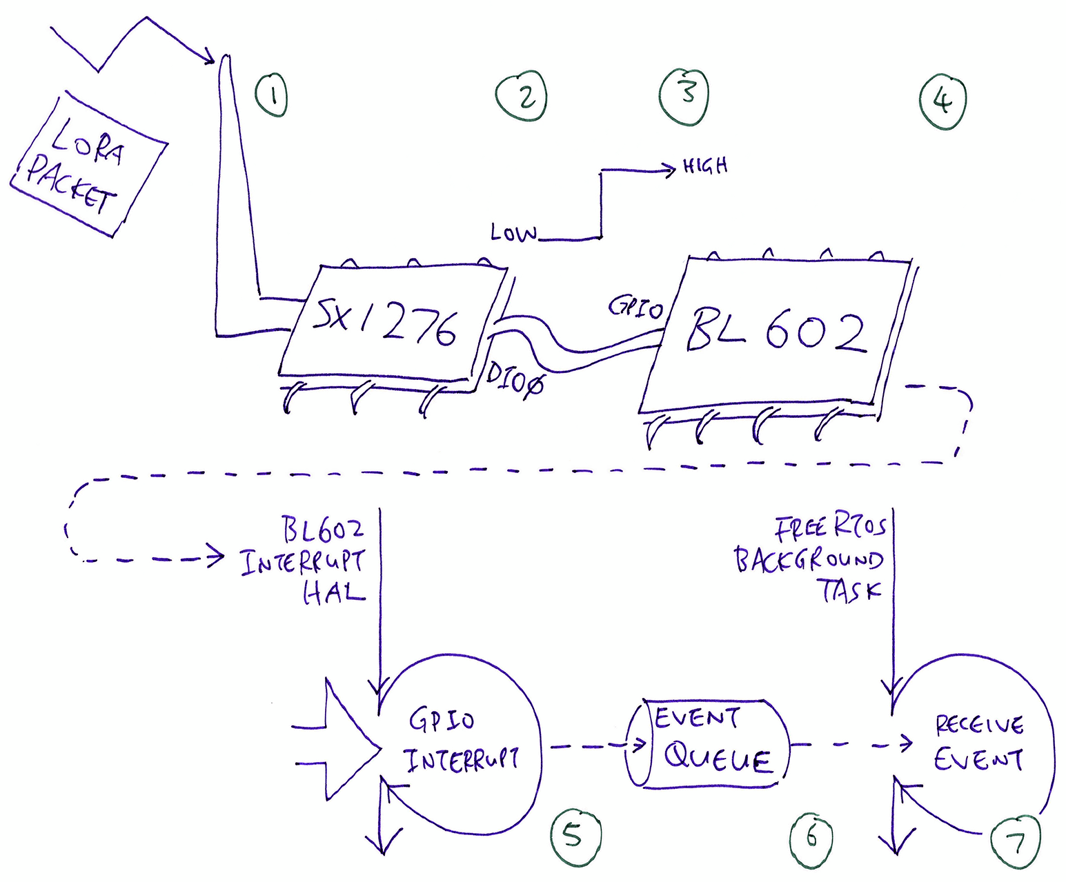
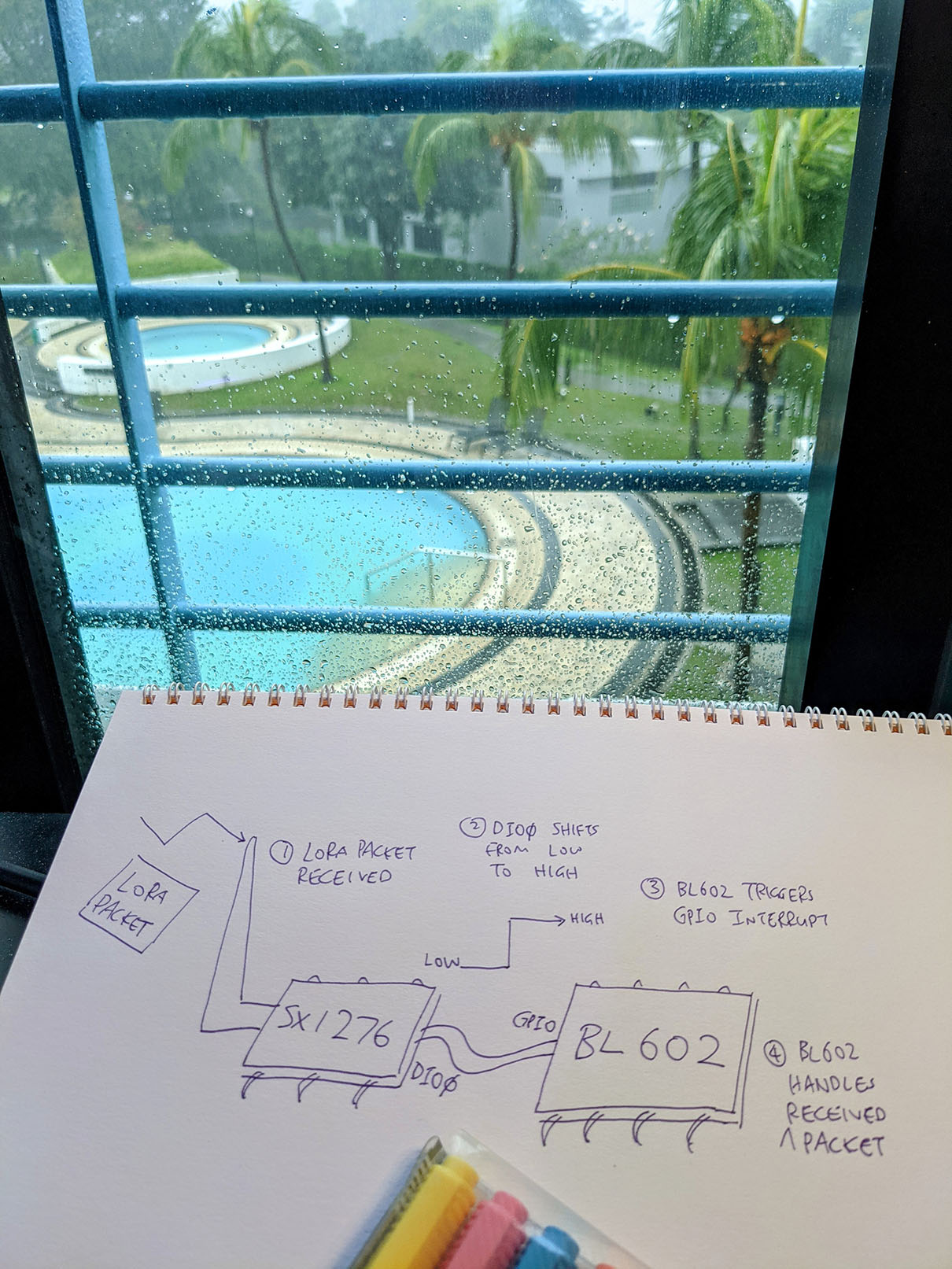
}Let’s talk about handling GPIO Interrupts on BL602…
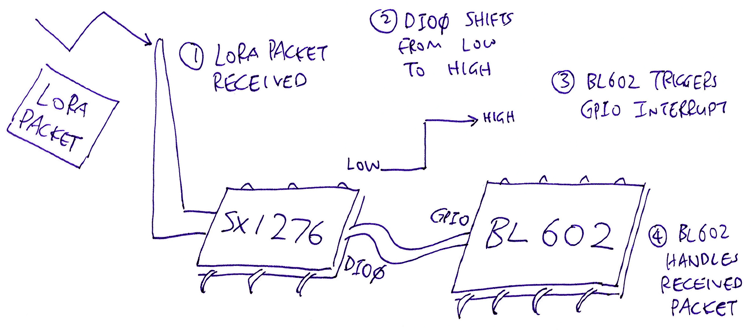
When our LoRa Transceiver (SX1276) receives a LoRa Packet…
It shifts the Logic Level of Pin DIO0 from Low to High
We shall configure BL602 to detect this shift in the connected GPIO Pin and trigger a GPIO Interrupt
The GPIO Interrupt Handler in our firmware code will then process the received LoRa Packet. (And reset DIO0 back to Low)
Here’s how we configure a GPIO Interrupt Handler on BL602: sx1276-board.c
//  SX1276 DIO0 is connected to BL602 at GPIO 11
#define SX1276_DIO0 11

//  Register GPIO Handler for DIO0
int rc = register_gpio_handler(   //  Register GPIO Handler...
    SX1276_DIO0,                  //  GPIO Pin Number
    SX1276OnDio0Irq,              //  GPIO Handler Function
    GLB_GPIO_INT_CONTROL_ASYNC,   //  Async Control Mode
    GLB_GPIO_INT_TRIG_POS_PULSE,  //  Trigger when GPIO level shifts from Low to High
    0,                            //  No pullup
    0                             //  No pulldown
);
assert(rc == 0);
This call to register_gpio_handler says…
When BL602 detects GPIO Pin 11 (connected to DIO0) shifting from Low to High (Positive Edge)…
BL602 will call our GPIO Handler Function SX1276OnDio0Irq
We’ll cover register_gpio_handler in the next section.
Then to enable GPIO Interrupts we call these functions from the BL602 Interrupt Hardware Abstraction Layer (HAL)…
//  Register Common Interrupt Handler for GPIO Interrupt
bl_irq_register_with_ctx(
    GPIO_INT0_IRQn,         //  GPIO Interrupt
    handle_gpio_interrupt,  //  Interrupt Handler
    NULL                    //  Argument for Interrupt Handler
);

//  Enable GPIO Interrupt
bl_irq_enable(GPIO_INT0_IRQn);
handle_gpio_interrupt is the low-level Interrupt Handler that will be called by the BL602 GPIO HAL when the GPIO Interrupt is triggered.
We’ll look inside handle_gpio_interrupt in a while.
Let’s look inside our function register_gpio_handler and learn how it registers a Handler Function for GPIO: sx1276-board.c
/// Register Handler Function for GPIO. Return 0 if successful.
/// GPIO Handler Function will run in the context of the Application Task, not the Interrupt Handler.
/// Based on bl_gpio_register in https://github.com/lupyuen/bl_iot_sdk/blob/master/components/hal_drv/bl602_hal/bl_gpio.c
static int register_gpio_handler(
    uint8_t gpioPin,         //  GPIO Pin Number
    DioIrqHandler *handler,  //  GPIO Handler Function
    uint8_t intCtrlMod,      //  GPIO Interrupt Control Mode (see below)
    uint8_t intTrgMod,       //  GPIO Interrupt Trigger Mode (see below)
    uint8_t pullup,          //  1 for pullup, 0 for no pullup
    uint8_t pulldown) {      //  1 for pulldown, 0 for no pulldown
Above are the parameters for register_gpio_handler.
The GPIO Interrupt Control Modes are…
GLB_GPIO_INT_CONTROL_SYNC: Synchronous Mode
(We never use sync mode)
GLB_GPIO_INT_CONTROL_ASYNC: Asynchronous Mode
(We ALWAYS use async mode)
The BL602 Reference Manual doesn’t mention GPIO Interrupt Control modes. But according to the BL602 HAL code, only Async Mode should be used. (See this)
The GPIO Interrupt Trigger Mode specifies how the GPIO should trigger the interrupt…
GLB_GPIO_INT_TRIG_NEG_PULSE: Negative Edge Pulse Trigger
Trigger the interrupt when the GPIO Logic Level shifts from High to Low
GLB_GPIO_INT_TRIG_POS_PULSE: Positive Edge Pulse Trigger
Trigger the interrupt when the GPIO Logic Level shifts from Low to High
(We use this for SX1276)
GLB_GPIO_INT_TRIG_NEG_LEVEL: Negative Edge Level Trigger (32k 3T)
Trigger the interrupt when the GPIO Logic Level stays Low
GLB_GPIO_INT_TRIG_POS_LEVEL: Positive Edge Level Trigger (32k 3T)
Trigger the interrupt when the GPIO Logic Level stays High
The GPIO Interrupt Trigger Mode is (partially) documented in the BL602 Reference Manual (Section 3.2.12: “GPIO Interrupt”). (This BL602 HAL code offers more hints)
Our GPIO Handler Function handler shall be triggered through an Event (from the NimBLE Porting Layer). We’ll learn why later…
    //  Init the Event that will invoke the handler for the GPIO Interrupt
    int rc = init_interrupt_event(
        gpioPin,  //  GPIO Pin Number
        handler   //  GPIO Handler Function that will be triggered by the Event
    );
    assert(rc == 0);
Next we call GLB_GPIO_Func_Init to configure the pin as a GPIO Pin…
    //  Configure pin as a GPIO Pin
    GLB_GPIO_Type pins[1];
    pins[0] = gpioPin;
    BL_Err_Type rc2 = GLB_GPIO_Func_Init(
        GPIO_FUN_SWGPIO,  //  Configure as GPIO
        pins,             //  Pins to be configured
        sizeof(pins) / sizeof(pins[0])  //  Number of pins (1)
    );
    assert(rc2 == SUCCESS);
GLB_GPIO_Func_Init comes from the BL602 Standard Driver: bl602_glb.c
We configure the pin as a GPIO Input Pin (instead of GPIO Output)…
    //  Configure pin as a GPIO Input Pin
    rc = bl_gpio_enable_input(
        gpioPin,  //  GPIO Pin Number
        pullup,   //  1 for pullup, 0 for no pullup
        pulldown  //  1 for pulldown, 0 for no pulldown
    );
    assert(rc == 0);
Finally we disable the GPIO Pin Interrupt, configure the GPIO Interrupt Control and Trigger Modes, and enable the GPIO Pin Interrupt…
    //  Disable GPIO Interrupt for the pin
    bl_gpio_intmask(gpioPin, 1);

    //  Configure GPIO Pin for GPIO Interrupt
    bl_set_gpio_intmod(
        gpioPin,     //  GPIO Pin Number
        intCtrlMod,  //  GPIO Interrupt Control Mode (see below)
        intTrgMod    //  GPIO Interrupt Trigger Mode (see below)
    );

    //  Enable GPIO Interrupt for the pin
    bl_gpio_intmask(gpioPin, 0);
    return 0;
}
We’re ready to handle GPIO Interrupts triggered by our LoRa Transceiver!
There seems to be 2 types of GPIO Interrupts?
Yep, earlier we saw this…
//  Enable GPIO Interrupt
bl_irq_enable(GPIO_INT0_IRQn);
This enables the GPIO Interrupt for ALL GPIO Pins (by calling the BL602 Interrupt HAL).
Then we saw this…
//  Enable GPIO Interrupt for the pin
bl_gpio_intmask(gpioPin, 0);
This enables the GPIO Interrupt for ONE Specific GPIO Pin (by calling the BL602 GPIO HAL).
We need both to make GPIO Interrupts work.
GPIO Interrupt Handler vs GPIO Handler Function… Are these different things?
I’m sorry to muddle my dearest readers, they are indeed different things and they work at different levels…
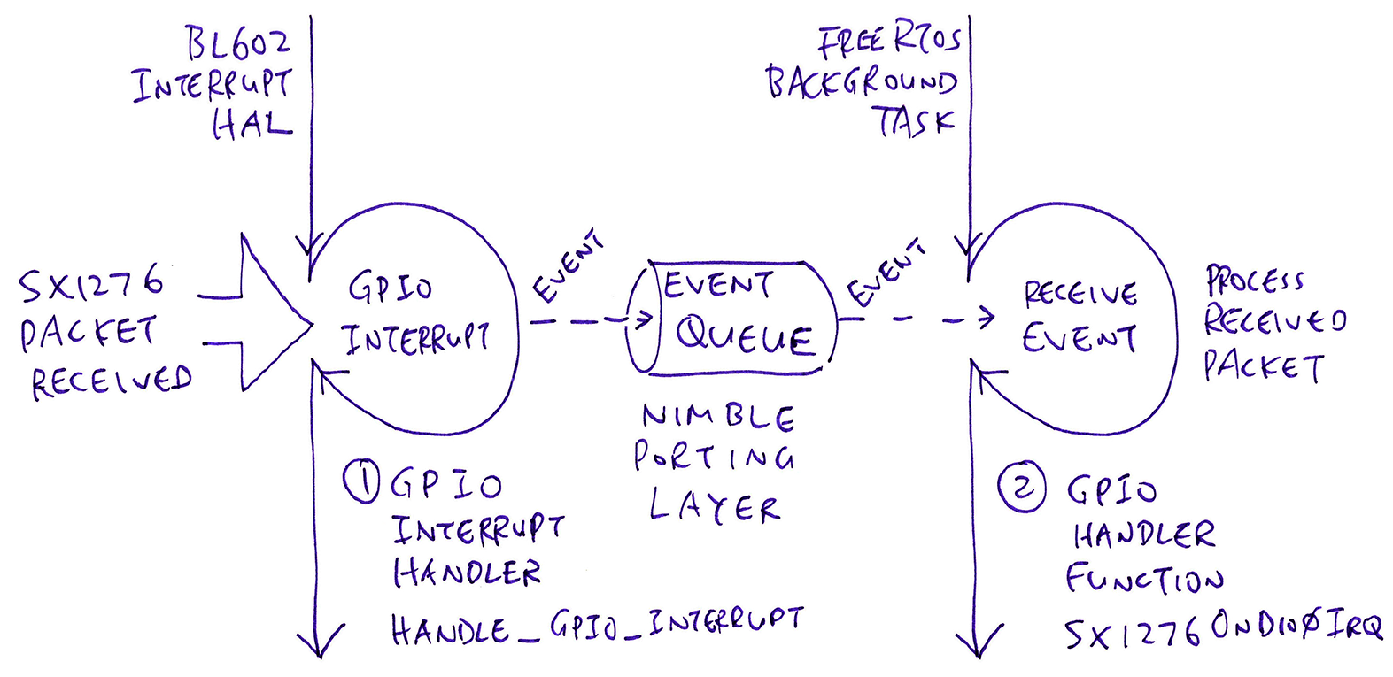
GPIO Interrupt Handler (handle_gpio_interrupt) is the low-level Interrupt Service Routine that handles the GPIO Interrupt.
This Interrupt Handler (called by BL602 Interrupt HAL) services the GPIO Interrupt that’s triggered when SX1276 receives a LoRa Packet.
GPIO Handler Function (like SX1276OnDio0Irq) is the high-level Application Function (running in a FreeRTOS Task) that processes the received LoRa Packet.
This Handler Function is invoked (indirectly) by the Interrupt Handler (via an Event from NimBLE Porting Layer).
(What’s an Event and why are we using it? We’ll learn about the NimBLE Porting Layer in the next chapter)
Let’s study the low-level GPIO Interrupt Handler handle_gpio_interrupt that services all GPIO Interrupts: sx1276-board.c
/// Maximum number of GPIO Pins that can be configured for interrupts
#define MAX_GPIO_INTERRUPTS 6  //  DIO0 to DIO5

/// Array of GPIO Pin Numbers that have been configured for interrupts
static uint8_t gpio_interrupts[MAX_GPIO_INTERRUPTS];

/// Array of Events for the GPIO Interrupts
static struct ble_npl_event gpio_events[MAX_GPIO_INTERRUPTS];

/// Interrupt Handler for GPIO Pins DIO0 to DIO5
static void handle_gpio_interrupt(void *arg) {

    //  Check all GPIO Interrupt Events
    for (int i = 0; i < MAX_GPIO_INTERRUPTS; i++) {

        //  Get the GPIO Pin Number for the Event
        GLB_GPIO_Type gpioPin = gpio_interrupts[i];

        //  Get the GPIO Interrupt Event
        struct ble_npl_event *ev = &gpio_events[i];
We start the GPIO Interrupt Handler handle_gpio_interrupt by iterating through the GPIO Interrupts that we have configured (for DIO0 to DIO5).
The configured GPIO Interrupts are stored in arrays gpio_interrupts and gpio_events like so…
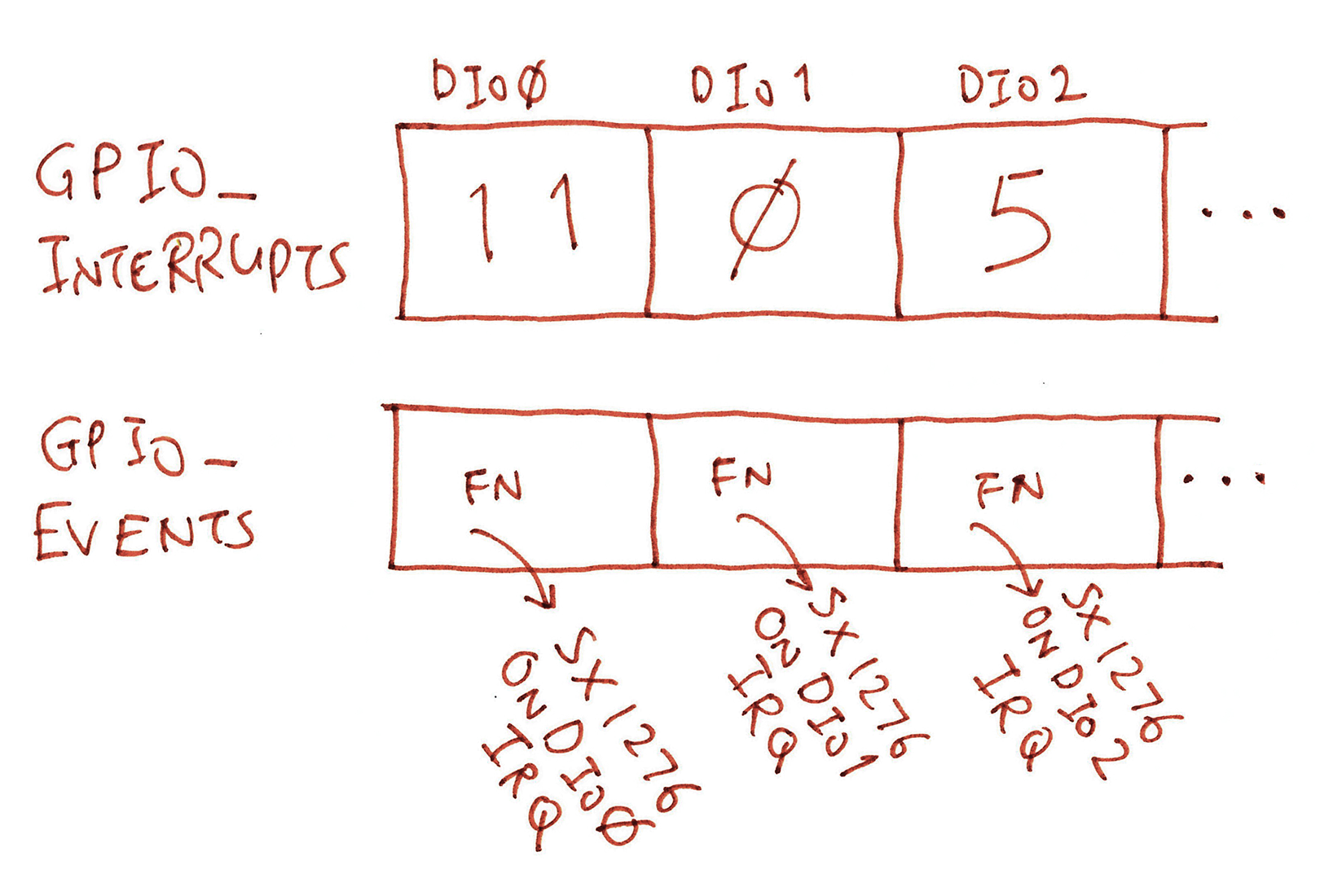
For the first iteration…
Since DIO0 is connected to GPIO Pin 11…
gpioPin shall be set to 11
(Via gpio_interrupts[0])
Since DIO0 is handled by the GPIO Handler Function SX1276OnDio0Irq…
ev shall be set to the Event that points to SX1276OnDio0Irq
(Via gpio_events[0])
(More about gpio_interrupts and gpio_events in the next chapter)
We allow unused GPIO Pins, and we skip them like so…
        //  If the Event is unused, skip it
        if (ev->fn == NULL) { continue; }
Next we fetch the Interrupt Status of the GPIO Pin, to determine whether this GPIO Pin has triggered the interrupt…
        //  Get the Interrupt Status of the GPIO Pin
        BL_Sts_Type status = GLB_Get_GPIO_IntStatus(gpioPin);
GLB_Get_GPIO_IntStatus comes from the BL602 Standard Driver: bl602_glb.c
If this GPIO Pin has indeed triggered the interrupt, we enqueue the Event (containing our GPIO Handler Function) for the Application Task to handle…
        //  If the GPIO Pin has triggered an interrupt...
        if (status == SET) {
            //  Forward the GPIO Interrupt to the Application Task to process
            enqueue_interrupt_event(
                gpioPin,  //  GPIO Pin Number
                ev        //  Event that will be enqueued for the Application Task
            );
        }
    }
}
In summary: Our GPIO Interrupt Handler…
Iterates through all configured GPIO Interrupts (DIO0 to DIO5)
Hunts for the GPIO Interrupts that have been triggered
Enqueues the GPIO Event (and Handler Function) for processing by the Application Task
Let’s look at enqueue_interrupt_event…
The time has come to reveal the final piece of code that handles GPIO Interrupts: enqueue_interrupt_event from sx1276-board.c
/// Interrupt Counters
int g_dio0_counter, g_dio1_counter, g_dio2_counter, g_dio3_counter, g_dio4_counter, g_dio5_counter, g_nodio_counter;

/// Enqueue the GPIO Interrupt to an Event Queue for the Application Task to process
static int enqueue_interrupt_event(
    uint8_t gpioPin,                //  GPIO Pin Number
    struct ble_npl_event *event) {  //  Event that will be enqueued for the Application Task

    //  Disable GPIO Interrupt for the pin
    bl_gpio_intmask(gpioPin, 1);
We start by disabling the GPIO Interrupt for the pin.
Here’s a helpful tip: Never clear the GPIO Interrupt Status by calling bl_gpio_int_clear…
    //  Note: DO NOT Clear the GPIO Interrupt Status for the pin!
    //  This will suppress subsequent GPIO Interrupts!
    //  bl_gpio_int_clear(gpioPin, SET);
bl_gpio_int_clear causes subsequent GPIO Interrupts to be suppressed. So we should never call it!
We can’t printf in an Interrupt Handler (for troubleshooting), but we can increment some Interrupt Counters that will be displayed by the spi_result command…
    //  Increment the Interrupt Counters
    if (SX1276_DIO0 >= 0 && gpioPin == (uint8_t) SX1276_DIO0) { g_dio0_counter++; }
    //  Omitted: Increment Interrupt Counters
    //  for DIO1 to DIO4
    ...
    else if (SX1276_DIO5 >= 0 && gpioPin == (uint8_t) SX1276_DIO5) { g_dio5_counter++; }
    else { g_nodio_counter++; }
Next we add the Interrupt Event (with the Handler Function inside) to the Event Queue (from the NimBLE Porting Layer)…
    //  Use Event Queue to invoke Event Handler in the Application Task,
    //  not in the Interrupt Context
    if (event != NULL && event->fn != NULL) {
        extern struct ble_npl_eventq event_queue;
        ble_npl_eventq_put(&event_queue, event);
    }
(In the next chapter we shall see the Background Task that will receive the Event and process the received LoRa Packet)
We finish up by enabling the GPIO Interrupt for the pin…
    //  Enable GPIO Interrupt for the pin
    bl_gpio_intmask(gpioPin, 0);
    return 0;
}
And that’s how we handle GPIO Interrupts on BL602!
Earlier we registered the GPIO Handler Function for DIO0. What about DIO1 to DIO5?
Here’s how we actually register the GPIO Handler Functions for DIO0 to DIO5, in a single shot…
First we define the GPIO Pins for DIO0 to DIO5: sx1276.h
#define SX1276_DIO0        11  //  DIO0: Trigger for Packet Received
#define SX1276_DIO1         0  //  DIO1: Trigger for Sync Timeout
#define SX1276_DIO2         5  //  DIO2: Trigger for Change Channel (Spread Spectrum / Frequency Hopping)
#define SX1276_DIO3        12  //  DIO3: Trigger for CAD Done
#define SX1276_DIO4        -1  //  DIO4: Unused (FSK only)
#define SX1276_DIO5        -1  //  DIO5: Unused (FSK only)
Next we define the GPIO Handler Functions for DIO0 to DIO5: sx1276.c
//  DIO Handler Functions
DioIrqHandler *DioIrq[] = {
    SX1276OnDio0Irq, SX1276OnDio1Irq,
    SX1276OnDio2Irq, SX1276OnDio3Irq,
    SX1276OnDio4Irq, NULL };  //  DIO5 not used for LoRa Modulation
Then we pass the DIO Handler Functions DioIrq to the function SX1276IoIrqInit defined in sx1276-board.c
/// Register GPIO Interrupt Handlers for DIO0 to DIO5.
/// Based on hal_button_register_handler_with_dts in https://github.com/lupyuen/bl_iot_sdk/blob/master/components/hal_drv/bl602_hal/hal_button.c
void SX1276IoIrqInit(DioIrqHandler **irqHandlers) {

    //  DIO0: Trigger for Packet Received and Packet Transmitted
    if (SX1276_DIO0 >= 0 && irqHandlers[0] != NULL) {
        int rc = register_gpio_handler(       //  Register GPIO Handler...
            SX1276_DIO0,                  //  GPIO Pin Number
            irqHandlers[0],               //  GPIO Handler Function
            GLB_GPIO_INT_CONTROL_ASYNC,   //  Async Control Mode
            GLB_GPIO_INT_TRIG_POS_PULSE,  //  Trigger when GPIO level shifts from Low to High
            0,                            //  No pullup
            0                             //  No pulldown
        );
        assert(rc == 0);
    }
This is similar to the code we’ve seen earlier for registering the GPIO Handler Function for DIO0.
The code for DIO1 to DIO5 looks highly similar…
    //  Omitted: Register GPIO Handler Functions
    //  for DIO1 to DIO4
    ...

    //  DIO5: Unused (FSK only)
    if (SX1276_DIO5 >= 0 && irqHandlers[5] != NULL) {
        int rc = register_gpio_handler(       //  Register GPIO Handler...
            SX1276_DIO5,                  //  GPIO Pin Number
            irqHandlers[5],               //  GPIO Handler Function
            GLB_GPIO_INT_CONTROL_ASYNC,   //  Async Control Mode
            GLB_GPIO_INT_TRIG_POS_PULSE,  //  Trigger when GPIO level shifts from Low to High
            0,                            //  No pullup
            0                             //  No pulldown
        );
        assert(rc == 0);
    }
To wrap up, we register the GPIO Interrupt Handler and enable GPIO Interrupts (as explained earlier)…
    //  Register Common Interrupt Handler for GPIO Interrupt
    bl_irq_register_with_ctx(
        GPIO_INT0_IRQn,         //  GPIO Interrupt
        handle_gpio_interrupt,  //  Interrupt Handler
        NULL                    //  Argument for Interrupt Handler
    );

    //  Enable GPIO Interrupt
    bl_irq_enable(GPIO_INT0_IRQn);
}
That is all… We register the GPIO Handler Functions for DIO0 to DIO5 with a single call to SX1276IoIrqInit.
(Our SX1276 Driver calls SX1276IoIrqInit here)
Move Fast OR Break Things… Choose ONE!
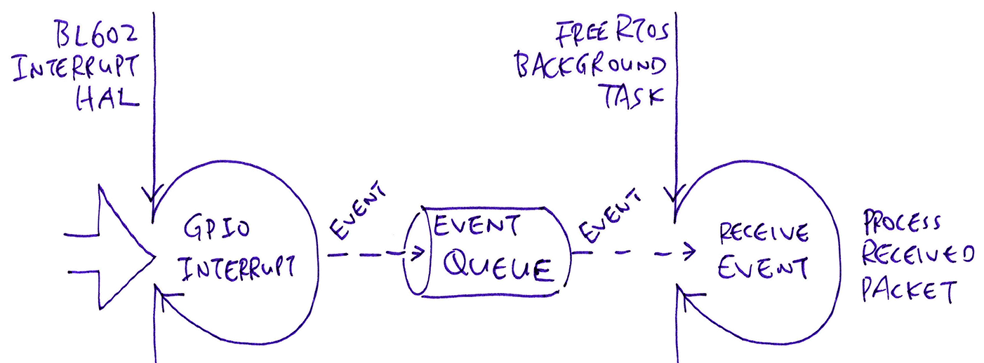
Handling an interrupt gets tricky for any Embedded Program…
Interrupts are Time-Sensitive: We can’t take too long to handle an interrupt… Other interrupts may be waiting on us!
(Lag ensues)
No Blocking Input / Output: Suppose our SX1276 Interrupt Handler needs to send an SPI Command to reset DIO0.
That’s no-no because our Interrupt Handler would block waiting for the SPI operation to complete. And hold up other interrupts.
No Console Output: Troubleshooting an Interrupt Handler gets challenging because we can’t show anything on the console (due to (1) and (2) above).
(Also challenging: Handling errors in an Interrupt Handler)
Hence some chunks of our Interrupt Handling Logic would need to run inside a higher-level, lower-priority Application Task. Like this…
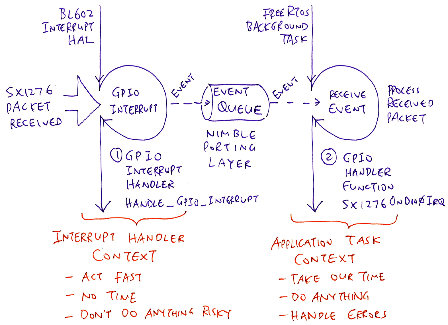
Our Interrupt Handler (left) would need to signal the Application Task (right) to do some work.
We’ll do this with FreeRTOS, no?
Let’s do this with NimBLE Porting Layer instead. It’s a library of multitasking functions that’s portable to multiple operating systems: FreeRTOS, Mynewt, NuttX, RIOT.
(And it looks simpler for folks who are new to FreeRTOS)
We start by creating the Background Task (right side of above pic) that will process the received LoRa Packets: demo.c
//  Create a FreeRTOS Task that runs task_callback
nimble_port_freertos_init(
    task_callback  //  Callback Function for the Task
);
We call nimble_port_freertos_init (from the NimBLE Porting Layer) to start a FreeRTOS Background Task that runs the function task_callback.
The function task_callback loops forever, doing work in the background…
/// Task Function that works in the background
static void task_callback(void *arg) {
    //  Loop forever doing work
    for (;;) {
        ...
    }
}
Let’s give it some work to do, by sending an Event…
Our Background Task shall receive Events from an Event Queue and process them.
We define our Event and Event Queue like so: demo.c
/// Event Queue containing Events to be processed
struct ble_npl_eventq event_queue;

/// Event to be added to the Event Queue
struct ble_npl_event event;
To initialise the Event and Event Queue, we call ble_npl_event_init and ble_npl_eventq_init like this: demo.c
/// Command to create a FreeRTOS Task with NimBLE Porting Layer
static void create_task(char *buf, int len, int argc, char **argv) {
    //  Init the Event Queue
    ble_npl_eventq_init(&event_queue);

    //  Init the Event
    ble_npl_event_init(
        &event,        //  Event
        handle_event,  //  Event Handler Function
        NULL           //  Argument to be passed to Event Handler
    );

    //  Create a FreeRTOS Task to process the Event Queue
    nimble_port_freertos_init(task_callback);
}
This call to ble_npl_event_init says…
When our Background Task receives the Event…
Execute the function handle_event to process the Event
Here’s a bare-bones Event Handler: demo.c
/// Handle an Event
static void handle_event(struct ble_npl_event *ev) {
    printf("\r\nHandle an event\r\n");
}
handle_event processes an Event by printing a message.
Later we’ll see a more sophisticated Event Handler for processing received LoRa Packets.
To send an Event into an Event Queue, we call ble_npl_eventq_put like so: demo.c
/// Command to enqueue an Event into the Event Queue with NimBLE Porting Layer
static void put_event(char *buf, int len, int argc, char **argv) {
    //  Add the Event to the Event Queue
    ble_npl_eventq_put(
        &event_queue,  //  Event Queue
        &event         //  Event to be added to Event Queue
    );
}
Our Background Task will…
Wake up
Receive the Event
Execute the Event Handler (handle_event)
We’ll learn how in the next section.
Is it OK to call this from an Interrupt Handler?
Yep it’s perfectly OK to call ble_npl_eventq_put from an Interrupt Handler.
In fact the implementation of ble_npl_eventq_put differs slightly for Interupt Handlers vs Application Tasks. (See this)
This is another reason for calling NimBLE Porting Layer instead of FreeRTOS… NimBLE Porting Layer handles the nitty-gritty on our behalf.
Here’s the code inside our Background Task that receives Events and executes the Event Handlers: demo.c
/// Task Function that dequeues Events from the Event Queue and processes the Events
static void task_callback(void *arg) {
    //  Loop forever handling Events from the Event Queue
    for (;;) {
        //  Get the next Event from the Event Queue
        struct ble_npl_event *ev = ble_npl_eventq_get(
            &event_queue,  //  Event Queue
            1000           //  Timeout in 1,000 ticks
        );

        //  If no Event due to timeout, wait for next Event
        if (ev == NULL) { continue; }
task_callback loops forever, calling ble_npl_eventq_get to receive Events from our Event Queue.
We’ve set a timeout of 1,000 ticks. (Yes it sounds arbitrary) If we don’t receive an Event in 1,000 ticks, we loop and retry.
When we receive an Event…
We call ble_npl_eventq_remove to remove the Event from the Event Queue
Then we call ble_npl_event_run to execute the Event Handler (like handle_event)
        //  Remove the Event from the Event Queue
        ble_npl_eventq_remove(&event_queue, ev);

        //  Trigger the Event Handler Function (handle_event)
        ble_npl_event_run(ev);
    }
}
And that’s how we process an Event Queue with a Background Task!
This Background Task looks so simple and generic… Will it work for all types of Events?
Yes! Remember that we can configure the Event Handler for our Event…
//  Set the Event handler for the Event
ble_npl_event_init(   //  Init the Event for...
    ev,               //  Event
    handler,          //  Event Handler Function
    NULL              //  Argument to be passed to Event Handler
);
In the next section we’ll learn to use multiple Events (with different Event Handlers) to process LoRa Packets.
Is there a way to test our Event Queue and Background Task?
Yes, by sending a test Event. See this…
Can we create multiple Background Tasks?
Sorry we can’t. Perhaps by modding NimBLE Porting Layer we can create multiple Background Tasks. (See this)
Earlier we have defined the GPIO Handler Functions that will process the interrupts from our LoRa Transceiver (DIO0 to DIO5)…
//  DIO Handler Functions
DioIrqHandler *DioIrq[] = {
    SX1276OnDio0Irq, SX1276OnDio1Irq,
    SX1276OnDio2Irq, SX1276OnDio3Irq,
    SX1276OnDio4Irq, NULL };  //  DIO5 not used for LoRa Modulation
How shall we trigger these GPIO Handler Functions… From our GPIO Interrupt Handler?
Easy: We use an Array of Events! From sx1276-board.c
/// Maximum number of GPIO Pins that can be configured for interrupts
#define MAX_GPIO_INTERRUPTS 6  //  DIO0 to DIO5

/// Array of GPIO Pin Numbers that have been configured for interrupts
static uint8_t gpio_interrupts[MAX_GPIO_INTERRUPTS];

/// Array of Events for the GPIO Interrupts
static struct ble_npl_event gpio_events[MAX_GPIO_INTERRUPTS];
Our Event Array gpio_events points to the GPIO Handler Functions (via the Event Handler)…
As explained earlier, our GPIO Interrupt Handler calls enqueue_interrupt_event to enqueue the Events from gpio_events into the Event Queue. (See this)
How are the arrays gpio_interrupts and gpio_events populated?
We call init_interrupt_event to initialise the gpio_interrupts and gpio_events arrays. (See this)
Remember that our LoRa SX1276 Transceiver will listen 5 seconds for incoming packets… Then we stop it to conserve battery power?
We do that with a Callout Timer from the NimBLE Porting Layer. Here’s how we initialise a Callout Timer: sx1276.c
//  Define the Callout Timer
struct ble_npl_callout timer;

//  Init the Callout Timer with the Callback Function
ble_npl_callout_init(
    &timer,        //  Callout Timer
    &event_queue,  //  Event Queue that will handle the Callout upon timeout
    f,             //  Callback Function
    arg            //  Argument to be passed to Callback Function
);
When the Callout Timer expires, the Callback Function f will be called by our Background Task (via the Event Queue).
Here’s how we set the Callout Timer to expire in microsecs microseconds: sx1276.c
//  Assume that Callout Timer has been stopped.
//  Convert microseconds to ticks.
ble_npl_time_t ticks = ble_npl_time_ms_to_ticks32(
    microsecs / 1000  //  Duration in milliseconds
);

//  Wait at least 1 tick
if (ticks == 0) { ticks = 1; }

//  Trigger the Callout Timer after the elapsed ticks
ble_npl_error_t rc = ble_npl_callout_reset(
    &timer,  //  Callout Timer
    ticks    //  Number of ticks
);
assert(rc == 0);
To stop a Callout Timer (and cancel the pending callback), we do this: sx1276.c
//  If Callout Timer is still running...
if (ble_npl_callout_is_active(&timer)) {
    //  Stop the Callout Timer
    ble_npl_callout_stop(&timer);
}
Sometimes we need to suspend the current task and wait a short while. (Maybe to ponder our life choices) Here’s how: sx1276.c
//  Convert microseconds to ticks
ble_npl_time_t ticks = ble_npl_time_ms_to_ticks32(
    microsecs / 1000  //  Duration in milliseconds
);

//  Wait at least 1 tick
if (ticks == 0) { ticks = 1; }

//  Wait for the ticks
ble_npl_time_delay(ticks);How do we add the NimBLE Porting Layer to our own BL602 programs?
Add the BL602 Library nimble-porting-layer to the BL602 project as described here…
Alternatively, copy these source files from the BL602 LoRa Firmware to your program…
Be sure to Enable Assertion Failure Messages by adding this function to main.c (or demo.c)…
/// TODO: We now show assertion failures in development.
/// For production, comment out this function to use the system default,
/// which loops forever without messages.
void __assert_func(const char *file, int line, const char *func, const char *failedexpr)
{
    //  Show the assertion failure, file, line, function name
	printf("Assertion Failed \"%s\": file \"%s\", line %d%s%s\r\n",
        failedexpr, file, line, func ? ", function: " : "",
        func ? func : "");
	//  Loop forever, do not pass go, do not collect $200
	for (;;) {}
}
The above source files were ported from the Apache NimBLE project with minor changes…
(More about NimBLE Porting Layer)
(Why NimBLE Porting Layer feels right)
Today we shall install RAKwireless WisBlock to transmit LoRa Packets to BL602 for testing.
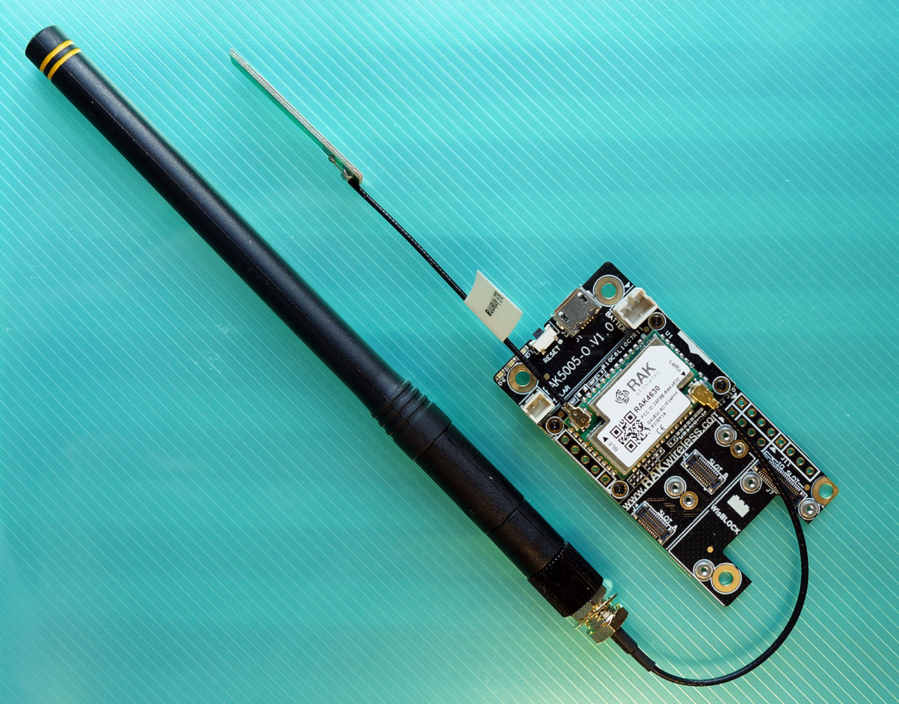
RAKwireless WisBlock LPWAN Module mounted on WisBlock Base Board
Connect the following components according to the pic above…
WisBlock LPWAN Module: This is the Nordic nRF52840 Microcontroller with Semtech SX1262 LoRa Transceiver. (More about this)
Mount the LPWAN Module onto the WisBlock Base Board.
(The LPWAN Module is already mounted when get the WisBlock Connected Box)
WisBlock Base Board: This provides power to the LPWAN Module and exposes the USB and I/O ports. (More about this)
The LPWAN Module should be mounted on the Base Board.
LoRa Antenna: Connect the LoRa Antenna to the LPWAN Module.
(That’s the black rod. Use the Antenna Adapter Cable)
Bluetooth LE Antenna: Connect the Bluetooth LE Antenna to the LPWAN Module.
(The stringy flappy thingy)
The above components are shipped in the WisBlock Connected Box. (Which includes many more goodies!)
Follow the instructions in this excellent article to install VSCode and PlatformIO…
Remember to install the LoRa Library SX126x-Arduino according to the steps above.
(We may skip the LoRaWAN OTAA Example)
Find out which LoRa Frequency we should use for your region…
We’ll set the LoRa Frequency in a while.
Enter this at the command line…
## Download the wisblock-lora-transmitter source code
git clone --recursive https://github.com/lupyuen/wisblock-lora-transmitter
In VSCode, click File → Open Folder
Select the folder that we have just downloaded: wisblock-lora-transmitter
Edit the file src/main.cpp
Look for this code…
// Define LoRa parameters.
// TODO: Change RF_FREQUENCY for your region
#define RF_FREQUENCY 923000000  // Hz
Change 923 to the LoRa Frequency for your region: 434, 780, 868, 915 or 923
Modify the LoRa Parameters in src/main.cpp so that they match those in our BL602 LoRa Firmware
Build the LoRa Firmware by clicking the Build icon at the lower left…
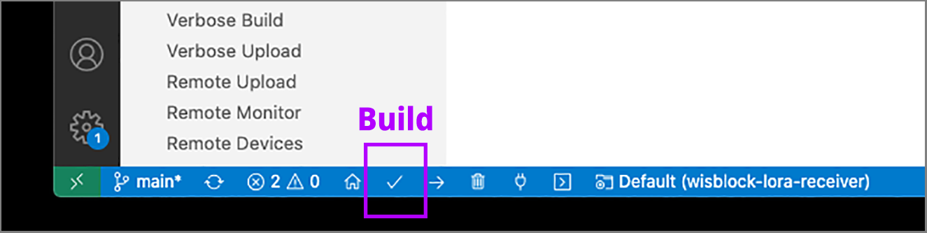
We should see this…
Processing wiscore_rak4631 (platform: nordicnrf52; board: wiscore_rak4631; framework: arduino)
...
Building in release mode
Checking size .pio/build/wiscore_rak4631/firmware.elf
Advanced Memory Usage is available via "PlatformIO Home > Project Inspect"
RAM:   [          ]   3.1% (used 7668 bytes from 248832 bytes)
Flash: [=         ]   7.3% (used 59800 bytes from 815104 bytes)
=========================== [SUCCESS] Took 4.49 seconds ===========================
This WisBlock code is based on the (now obsolete) WisBlock LoRa Transmitter Example: LoRaP2P_TX.ino
Connect WisBlock to our computer’s USB port
Flash the LoRa Firmware to WisBlock by clicking the Upload icon…
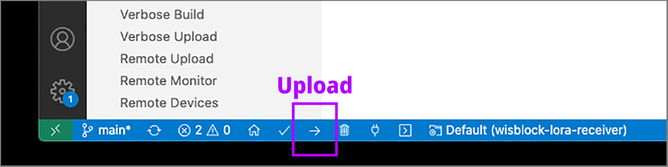
We should see this…
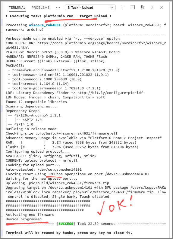
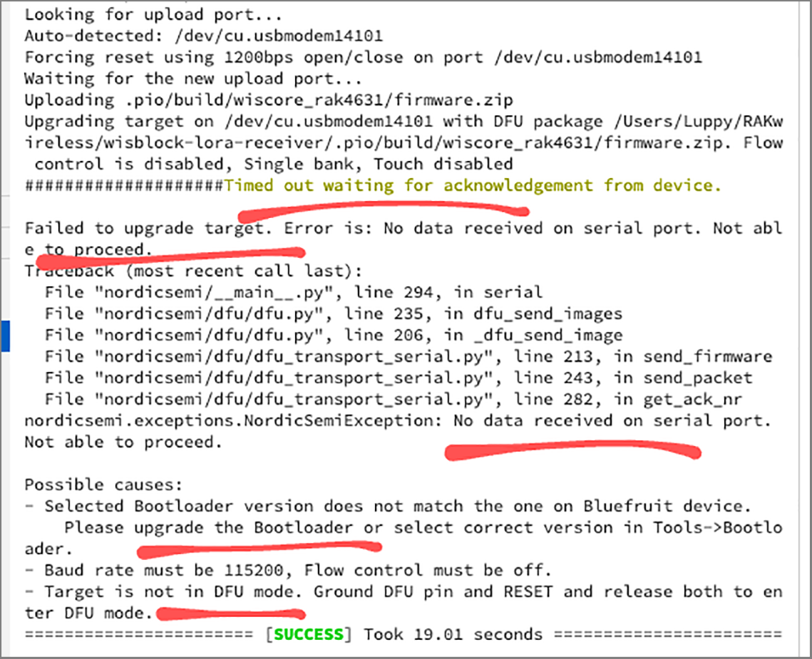
If we see the message…
Timed out waiting for acknowledgement from deviceThen disconnect WisBlock from the USB port, reconnect and flash again.
Run the LoRa Firmware by clicking the Monitor icon…
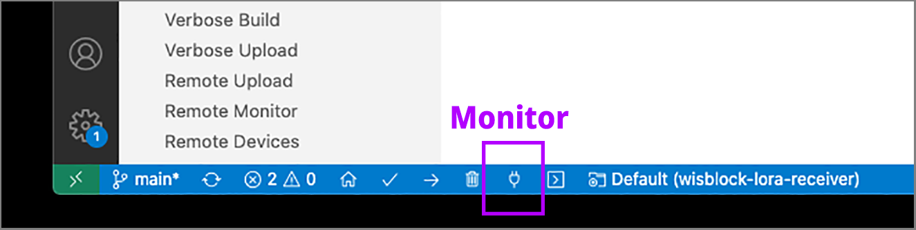
We should see this…
> Executing task: platformio device monitor <
--- Miniterm on /dev/cu.usbmodem14201  9600,8,N,1 ---
--- Quit: Ctrl+C | Menu: Ctrl+T | Help: Ctrl+T followed by Ctrl+H ---
...
OnTxDone
OnTxDone
OnTxDone
WisBlock is now transmitting a LoRa Packet ("Hello") every 5 seconds. (See this)
If we sniff the airwaves with a Software Defined Radio, we will see the distinctive LoRa Chirp…
Let’s run the LoRa Demo Firmware for BL602 to receive the LoRa Packets transmitted by RAKwireless WisBlock.
Find out which LoRa Frequency we should use for your region…
Download the Firmware Binary File sdk_app_lora.bin for your LoRa Frequency…
Alternatively, we may build the Firmware Binary File sdk_app_lora.bin from the source code…
## Download the lorarecv branch of lupyuen's bl_iot_sdk
git clone --recursive --branch lorarecv https://github.com/lupyuen/bl_iot_sdk
cd bl_iot_sdk/customer_app/sdk_app_lora

## TODO: Set the LoRa Frequency in sdk_app_lora/demo.c.
## Edit the file and look for the line...
##   #define USE_BAND_923
## Change 923 to the LoRa Frequency for your region:
##   434, 780, 868, 915 or 923 MHz
## See https://www.thethingsnetwork.org/docs/lorawan/frequencies-by-country.html

## TODO: Change this to the full path of bl_iot_sdk
export BL60X_SDK_PATH=$HOME/bl_iot_sdk
export CONFIG_CHIP_NAME=BL602
make

## For WSL: Copy the firmware to /mnt/c/blflash, which refers to c:\blflash in Windows
mkdir /mnt/c/blflash
cp build_out/sdk_app_lora.bin /mnt/c/blflash
More details on building bl_iot_sdk
(Remember to use the lorarecv branch, not the default master branch)
Follow these steps to install blflash…
We assume that our Firmware Binary File sdk_app_lora.bin has been copied to the blflash folder.
Set BL602 to Flashing Mode and restart the board…
For PineCone:
Set the PineCone Jumper (IO 8) to the H Position (Like this)
Press the Reset Button
For BL10:
Connect BL10 to the USB port
Press and hold the D8 Button (GPIO 8)
Press and release the EN Button (Reset)
Release the D8 Button
For Ai-Thinker Ai-WB2, Pinenut and MagicHome BL602:
Disconnect the board from the USB Port
Connect GPIO 8 to 3.3V
Reconnect the board to the USB port
Enter these commands to flash sdk_app_lora.bin to BL602 over UART…
## For Linux:
blflash flash build_out/sdk_app_lora.bin \
    --port /dev/ttyUSB0

## For macOS:
blflash flash build_out/sdk_app_lora.bin \
    --port /dev/tty.usbserial-1420 \
    --initial-baud-rate 230400 \
    --baud-rate 230400

## For Windows: Change COM5 to the BL602 Serial Port
blflash flash c:\blflash\sdk_app_lora.bin --port COM5
(For WSL: Do this under plain old Windows CMD, not WSL, because blflash needs to access the COM port)
More details on flashing firmware
Set BL602 to Normal Mode (Non-Flashing) and restart the board…
For PineCone:
Set the PineCone Jumper (IO 8) to the L Position (Like this)
Press the Reset Button
For BL10:
For Ai-Thinker Ai-WB2, Pinenut and MagicHome BL602:
Disconnect the board from the USB Port
Connect GPIO 8 to GND
Reconnect the board to the USB port
After restarting, connect to BL602’s UART Port at 2 Mbps like so…
For Linux:
screen /dev/ttyUSB0 2000000For macOS: Use CoolTerm (See this)
For Windows: Use putty (See this)
Alternatively: Use the Web Serial Terminal (See this)
More details on connecting to BL602
Let’s enter some commands to transmit a LoRa Packet!
Press Enter to reveal the command prompt.
Enter help to see the available commands…
help
====User Commands====
create_task              : Create a task
put_event                : Add an event
init_driver              : Init LoRa driver
send_message             : Send LoRa message
receive_message          : Receive LoRa message
read_registers           : Read registers
spi_result               : Show SPI counters
blogset                  : blog pri set level
blogdump                 : blog info dump
bl_sys_time_now          : sys time now
First we create the Background Task that will process received LoRa Packets.
Enter this command…
create_taskThis command calls the function create_task, which we have seen earlier.
Then we initialise our LoRa Transceiver.
Enter this command…
init_driverThis command calls the function init_driver, which we have seen earlier.
We should see this…
init_driver
SX1276 init
SX1276 interrupt init
SX1276 register handler: GPIO 11
SX1276 register handler: GPIO 0
SX1276 register handler: GPIO 5
SX1276 register handler: GPIO 12
This says that register_gpio_handler has registered the GPIO Handler Functions for DIO0 to DIO3. (DIO4 and DIO5 are unused)
Our SX1276 Driver is now listening for GPIO Interrupts and handling them.
Then the GPIO Interrupt for DIO3 gets triggered automatically…
SX1276 DIO3: Channel activity detection (We’re not sure why this always happens when we initialise the driver… But it’s harmless)
Next we receive a LoRa Packet…
receive_messageThis command calls the function receive_message, which we have seen earlier.
We should see this…
receive_message
...
SX1276 DIO0: Packet received
Rx done: RadioEvents.RxDone
This says that the SX1276 Driver has received a LoRa Packet.
And the packet contains "Hello"…
Rx done: 48 65 6c 6c 6f (That’s the ASCII code for "Hello")
Remember that our SX1276 Transceiver will listen 5 seconds for incoming packets… Then it goes to sleep to conserve battery power?
Here’s what happens when then SX1276 Driver doesn’t receive any LoRa Packets within 5 seconds…
receive_message
...
SX1276 receive timeout
Rx timeout
Our BL602 Timer is triggered automatically after 5 seconds to put the SX1276 Transceiver to sleep.
Watch the receive timeout video on YouTube
Check out the receive timeout log
What could go wrong with our BL602 LoRa Receiver?
Sorry to sound so down… But many things can go wrong with our BL602 LoRa Receiver!
Here’s a BL602 LoRa troubleshooting guide…
BL602 not receiving any LoRa Packets?
Sniff the airwaves with a Spectrum Analyser or Software Defined Radio. (See below)
SX1276 not responding, or returning strange data?
Verify the SPI Connection by Reading the SX1276 Registers. (See below)
SX1276 still not receiving LoRa Packets?
Turn on SPI Tracing and check the SPI Commands. (See below)
SX1276 not triggering interrupts when LoRa Packets are received?
Check the SX1276 Interrupt Counters. (See below)
Background Task not processing the interrupts?
Test the Event Queue by sending an Event. (See below)
BL602 hitting a RISC-V Exception?
Turn on Stack Trace. (See below)
BL602 Stack Trace not helpful?
Do a Stack Dump. (See below)
Let’s go into the details.
It helps to validate that the LoRa Packets that we’re about to receive… Are actually in the airwaves!
Sniff the airwaves with a Spectrum Analyser or Software Defined Radio. Check that the LoRa Packets are centered at the right LoRa Frequency.
LoRa Packets have this distinctive shape, called a LoRa Chirp…
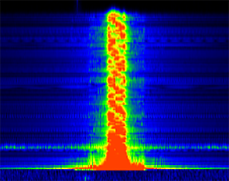
More about sniffing LoRa Packets…
Verify the SPI Connection between BL602 and SX1276 by entering the command read_registers…
read_registers
Register 0x02 = 0x1a
Register 0x03 = 0x0b
Register 0x04 = 0x00
Register 0x05 = 0x52
This command reads the SX1276 Registers over the SPI Connections.
If there’s a fault in the SPI wiring, we will see incorrect register values.
More about read_registers…
To enable SPI Tracing:
Set HAL_SPI_DEBUG to (1) like so…
//  Enable SPI Tracing
#define HAL_SPI_DEBUG (1)
Rebuild the firmware: make clean then make
We will see all SPI DMA Requests sent by BL602 to SX1276…
hal_spi_transfer = 1
transfer xfer[0].len = 1
Tx DMA src=0x4200cc58, dest=0x4000a288, size=1, si=1, di=0, i=1
Rx DMA src=0x4000a28c, dest=0x4200cc54, size=1, si=0, di=1, i=1
recv all event group.
More about SPI Tracing messages…
We may check the number of GPIO and SPI Interrupts triggered by SX1276 by entering the spi_result command…
spi_result
DIO0 Interrupts: 1
DIO3 Interrupts: 1
Tx Interrupts:   302
Rx Interrupts:   302
This demo video explains the Interrupt Counters…
To check whether our Event Queue and Background Task (from the NimBLE Porting Layer) are OK, do this…
If the Background Task has NOT been started, enter this command…
create_task(create_task should only be run once)
Then enter this command to enqueue an Event into our Event Queue…
put_eventWe should see this…
Handle an eventThis means that our Event Queue and Background Task are ready to handle Interrupt Events triggered by SX1276.
When our BL602 Firmware hits an Exception, we’ll see a message like this…
Exception Entry--->>>
mcause 38000001, mepc 00000000, mtval 00000000
Exception code: 1
  msg: Instruction access fault
This is not really helpful because it doesn’t show the Stack Trace: The function calls leading to the Exception.
To show the Stack Trace, edit the Makefile proj_config.mk (like sdk_app_lora/proj_config.mk) and add this…
# Show Stack Trace when we hit a RISC-V Exception,
# by enabling the Stack Frame Pointer.
# After setting this flag, do "make clean ; make"
CONFIG_ENABLE_FP:=1
Rebuild the firmware: make clean then make.
When BL602 hits an Exception, we’ll see this Stack Trace:
=== backtrace start ===
backtrace_stack: frame pointer=0x42011e70
backtrace: 0x2300ba88 (@ 0x42011e6c)
backtrace: 0x2300a852 (@ 0x42011e9c)
backtrace: 0x00000004   <--- TRAP
backtrace: INVALID!!!
=== backtrace end ===This shows the function calls leading to the Exception, so it’s more helpful for troubleshooting.
To find the source code that corresponds to the program address (like 0x2300ba88), follow the instructions here to generate the RISC-V Disassembly File…
For some types of BL602 Exceptions, the Stack Trace doesn’t appear to be meaningful.
(The Stack Trace points to the BL602 Exception Handler, not to the code that caused the Exception)
For such Exceptions, we need to dump the stack ourselves and analyse the trail of calls.
Here’s the function that dumps the stack: demo.c
/// Dump the current stack
void dump_stack(void)
{
    //  For getting the Stack Frame Pointer. Must be first line of function.
    uintptr_t *fp;

    //  Fetch the Stack Frame Pointer. Based on backtrace_riscv from
    //  https://github.com/bouffalolab/bl_iot_sdk/blob/master/components/bl602/freertos_riscv_ram/panic/panic_c.c#L76-L99
    __asm__("add %0, x0, fp" : "=r"(fp));
    printf("dump_stack: frame pointer=%p\r\n", fp);

    //  Dump the stack, starting at Stack Frame Pointer - 1
    printf("=== stack start ===\r\n");
    for (int i = 0; i < 128; i++) {
        uintptr_t *ra = (uintptr_t *)*(unsigned long *)(fp - 1);
        printf("@ %p: %p\r\n", fp - 1, ra);
        fp++;
    }
    printf("=== stack end ===\r\n\r\n");
}
We call dump_stack in the BL602 Exception Handler like this: bl_irq.c
//  Declare dump_stack
void dump_stack(void);

//  BL602 Exception Handler
void exception_entry(uint32_t mcause, uint32_t mepc, uint32_t mtval, uintptr_t *regs) {
        ...
        //  Show exception and stack trace
        __dump_exception_code_str(mcause & 0xFFFF);
        backtrace_now((int (*)(const char *fmt, ...))printf, regs);

        //  Dump the stack here
        printf("Exception Handler Stack:\r\n");
        dump_stack();

        while (1) { /*Deap loop now*/ }
When BL602 hits an Exception, we’ll see this Stack Dump…
Exception Handler Stack:
dump_stack: frame pointer=0x42011e70
=== stack start ===
...
@ 0x42011f20: 0x00000000
@ 0x42011f24: 0x00000000
@ 0x42011f28: 0x42011f50
@ 0x42011f2c: 0x23000cd2 <--
@ 0x42011f30: 0x04000000
@ 0x42011f34: 0x00000001
@ 0x42011f38: 0x4000a28cAfter a big chunk of nulls (omitted from above) we see a meaningful address…
0x23000cd2This address points to code that actually caused the Exception.
(We forgot to initialise the stack variable radio_events… ALWAYS INITIALISE STACK VARIABLES!)
Perhaps someday we shall fix the BL602 Stack Trace so that it displays the right program addresses…
Be sure to Enable Assertion Failure Messages by adding this function to main.c (or demo.c)…
/// TODO: We now show assertion failures in development.
/// For production, comment out this function to use the system default,
/// which loops forever without messages.
void __assert_func(const char *file, int line, const char *func, const char *failedexpr)
{
    //  Show the assertion failure, file, line, function name
	printf("Assertion Failed \"%s\": file \"%s\", line %d%s%s\r\n",
        failedexpr, file, line, func ? ", function: " : "",
        func ? func : "");
	//  Loop forever, do not pass go, do not collect $200
	for (;;) {}
}
Comment out this function when building the production firmware.
We have completed Level One of our epic quest for the Three Levels of LoRa!
Let’s move on to LoRa Levels Two and Three…
We shall install a LoRaWAN Gateway and join BL602 to The Things Network
But before that, we shall port the LoRaWAN Driver from Apache Mynewt OS to BL602
And before that, we shall clean up and reorganise the library files for NimBLE and SX1276
So eventually we shall build LoRaWAN Sensor Devices with BL602!
We have come a loooong way since I first experimented with LoRa in 2016…
Cheaper Transceivers: Shipped overnight from Thailand!
Mature Networks: LoRaWAN, The Things Network
Better Drivers: Thanks to Apache Mynewt OS!
Powerful Microcontrollers: Arduino Uno vs RISC-V BL602
Awesome Tools: RAKwireless WisBlock, Airspy SDR, RF Explorer
Now is the right time to build LoRa gadgets. Stay tuned for more LoRa and LoRaWAN Adventures!
Meanwhile there’s plenty more code in the BL602 IoT SDK to be deciphered and documented: ADC, DAC, WiFi, Bluetooth LE, …
Come Join Us… Make BL602 Better!
🙏 👍 😀
Got a question, comment or suggestion? Create an Issue or submit a Pull Request here…
lupyuen.github.io/src/lora2.md
Follow these steps to create a new BL602 Project (like sdk_app_lorawan)…
Download the Source Code for BL602 IoT SDK…
git clone --recursive https://github.com/lupyuen/bl_iot_sdkCopy the Project Folder for an existing Project in bl_iot_sdk/customer_app, like sdk_app_blinky…
Paste the Project Folder into bl_iot_sdk/customer_app and rename it (like sdk_app_lorawan)…
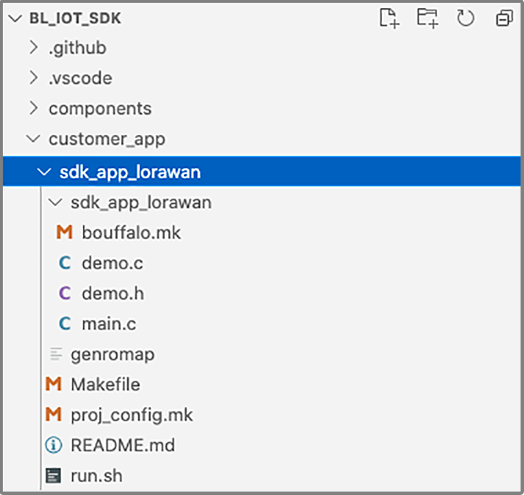
Be sure to rename the Sub Folder too. (The sdk_app_lorawan inside sdk_app_lorawan)
Delete the build_out folder if it exists.
Edit the Makefile in the new folder and set the Project Name: sdk_app_lorawan/Makefile
##  Set the project name
PROJECT_NAME := sdk_app_lorawan
Set the GCC Compiler Options in the Makefile (if any): sdk_app_lorawan/Makefile
## Define the GCC compiler options

## Set LoRa Region to 1 (AS923). See components/3rdparty/lorawan/include/node/lora_band.h
CFLAGS += -DCONFIG_LORA_NODE_REGION=1

## Do not auto-join the LoRaWAN Network
CFLAGS += -DLORA_APP_AUTO_JOIN=0
UPDATE: The above flags won’t work for C++ programs. Instead we should set CFLAGS and CPPFLAGS in bouffalo.mk inside the Sub Folder. (Here’s an example for TensorFlow Lite Firmware)
For macOS Only: Edit the run.sh script in the new folder and set the Project Name: sdk_app_lorawan/run.sh
##  Set the project name
export APP_NAME=sdk_app_lorawan
Build the project by entering these commands…
## TODO: Change this to the full path of bl_iot_sdk
export BL60X_SDK_PATH=$HOME/bl_iot_sdk
export CONFIG_CHIP_NAME=BL602

## TODO: Change sdk_app_lorawan to the project name
cd bl_iot_sdk/customer_app/sdk_app_lorawan
make
For macOS Only: We may build, flash and run the new firmware with the run.sh script instead…
## TODO: Change sdk_app_lorawan to the project name
cd bl_iot_sdk/customer_app/sdk_app_lorawan

## TODO Before Flashing: Switch GPIO 8 to Flashing Mode. Restart the BL602 board.

## Build, flash and run the firmware (with CoolTerm)
./run.sh

## TODO After Flashing: Switch GPIO 8 to Normal Mode. Restart the BL602 board.
Remember to edit README.md and fill in the project details
We’re now refactoring the LoRa Firmware Source Code from this article to create reusable BL602 Libraries…
To create your own BL602 Library…
Place the source files into a new folder under bl_iot_sdk/components/3rdparty
Here’s where we created the folder for NimBLE Porting Layer…
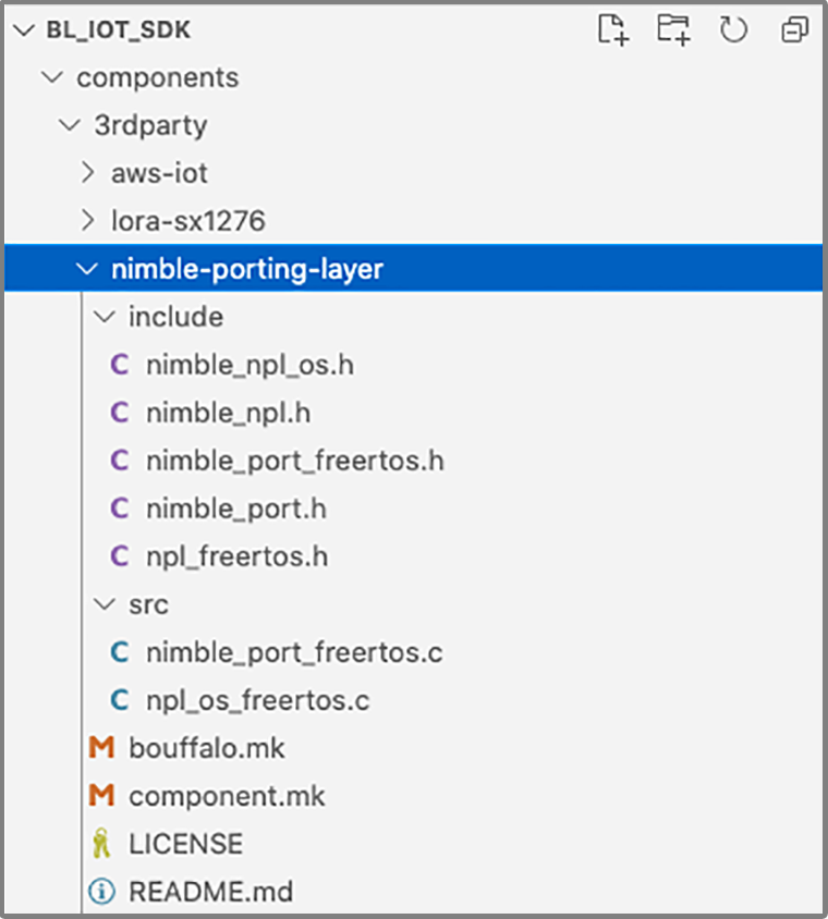
In the folder, create two subfolders…
include: For the include files (*.h)
src: For the source files (*.c)
In the same folder, create the file bouffalo.mk containing…
# Component Makefile
#

# Include Folders
COMPONENT_ADD_INCLUDEDIRS := include

# Object Files (*.o)
COMPONENT_OBJS := $(patsubst %.c,%.o, $(COMPONENT_SRCS))

# Source Folders
COMPONENT_SRCDIRS := src
In the same folder, create the file component.mk containing…
#
# Component Makefile
#

# Include Folders
COMPONENT_ADD_INCLUDEDIRS := include

# Source Folders
COMPONENT_SRCDIRS := src

# Check the submodule is initialised
COMPONENT_SUBMODULES :=
If there are multiple Include Folders or Source Folders, add them to COMPONENT_ADD_INCLUDEDIRS and COMPONENT_SRCDIRS in the above two files. Like so…
For GCC Compiler Options: We should set CFLAGS and CPPFLAGS in bouffalo.mk inside the Library Folder.
How do we reference the BL602 Library in our BL602 Project?
Edit the Makefile for our BL602 Project (like sdk_app_lora/Makefile)
Look for the INCLUDE_COMPONENTS section.
Insert a new INCLUDE_COMPONENTS line that specifies the names of the BL602 Libraries to be used.
So to use the BL602 Libraries lora-sx1276 and nimble-porting-layer, we would insert this line…
INCLUDE_COMPONENTS += lora-sx1276 nimble-porting-layerTo look neater, the Makefile for our LoRa Firmware defines a variable COMPONENTS_LORA like so: sdk_app_lora/Makefile
## Added this line to define COMPONENTS_LORA...
COMPONENTS_LORA    := lora-sx1276 nimble-porting-layer
COMPONENTS_BLSYS   := bltime blfdt blmtd bloop loopadc looprt loopset
COMPONENTS_VFS     := romfs
COMPONENTS_BLE     :=

INCLUDE_COMPONENTS += freertos_riscv_ram bl602 bl602_std hal_drv vfs yloop utils cli blog blog_testc
INCLUDE_COMPONENTS += easyflash4
INCLUDE_COMPONENTS += $(COMPONENTS_NETWORK)
INCLUDE_COMPONENTS += $(COMPONENTS_BLSYS)
INCLUDE_COMPONENTS += $(COMPONENTS_VFS)
## Added this line to reference COMPONENTS_LORA...
INCLUDE_COMPONENTS += $(COMPONENTS_LORA)
INCLUDE_COMPONENTS += $(PROJECT_NAME)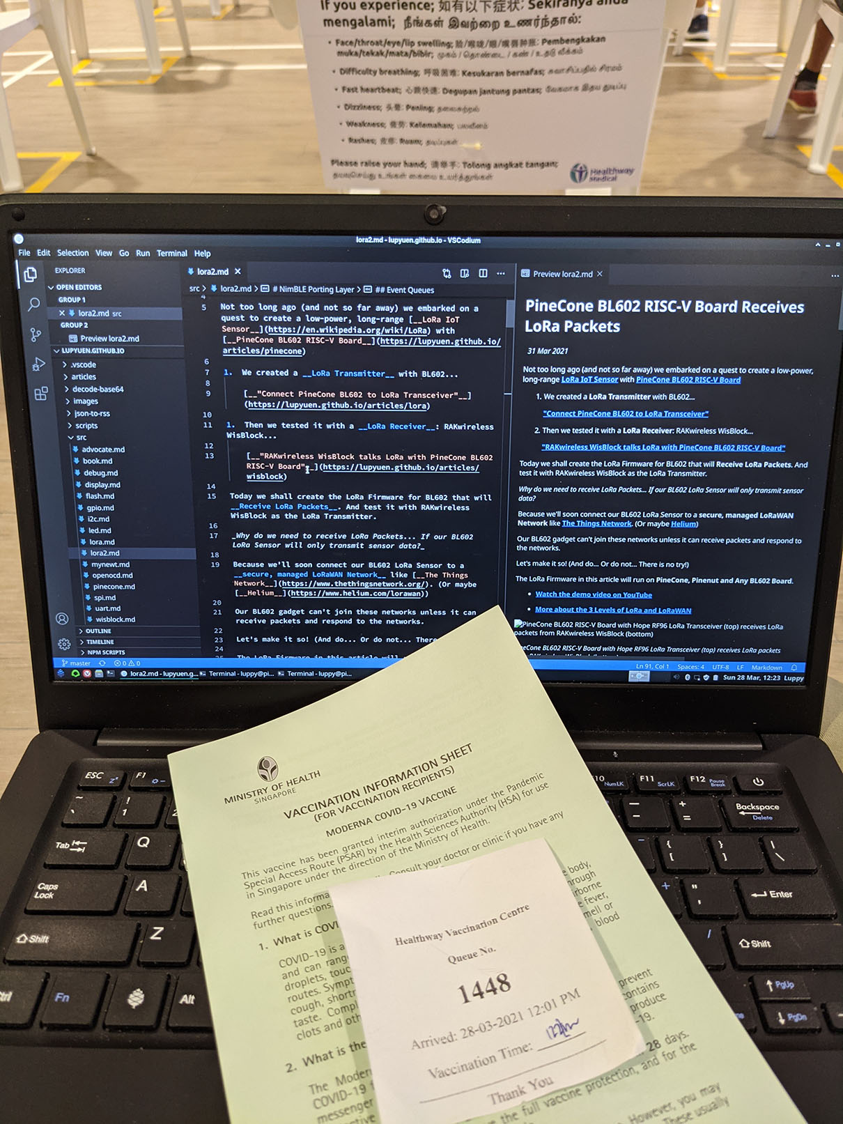
Pinebook Pro keeping me company during vaccination (Moderna)… Because bringing a PineCone would look so odd 👍