📝 30 Apr 2021
While testing a new LoRaWAN gadget (PineCone BL602), I bought a LoRaWAN Gateway from RAKwireless: RAK7248 WisGate Developer D4H Gateway.
Here’s what I learnt about settting up a LoRaWAN Network with WisGate Developer D4H… And testing it with the RAKwireless WisBlock dev kit in Arduino.
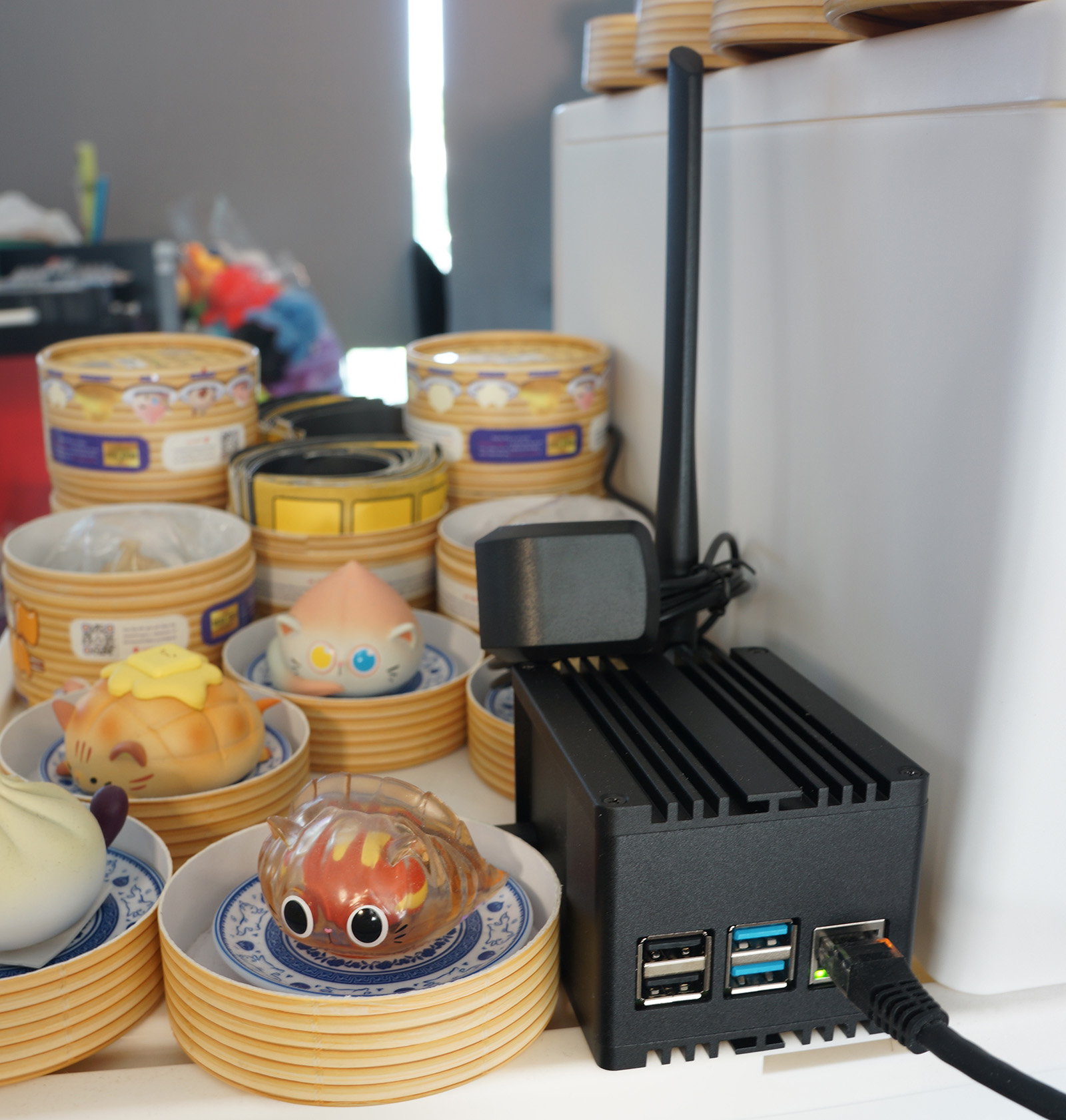
RAKwireless RAK7248 WisGate Developer D4H LoRaWAN Gateway
WisGate D4H is essentially a Raspberry Pi 4 + LoRa Network Concentrator (Semtech SX1302) in a sturdy IP30 box.
It exposes the same ports and connectors as a Raspberry Pi 4: Ethernet port, USB 2 and 3 ports, USB-C power, microSD Card.
But the HDMI and GPIO ports are no longer accessible. (We control the box over HTTP and SSH)
2 new connectors have been added…
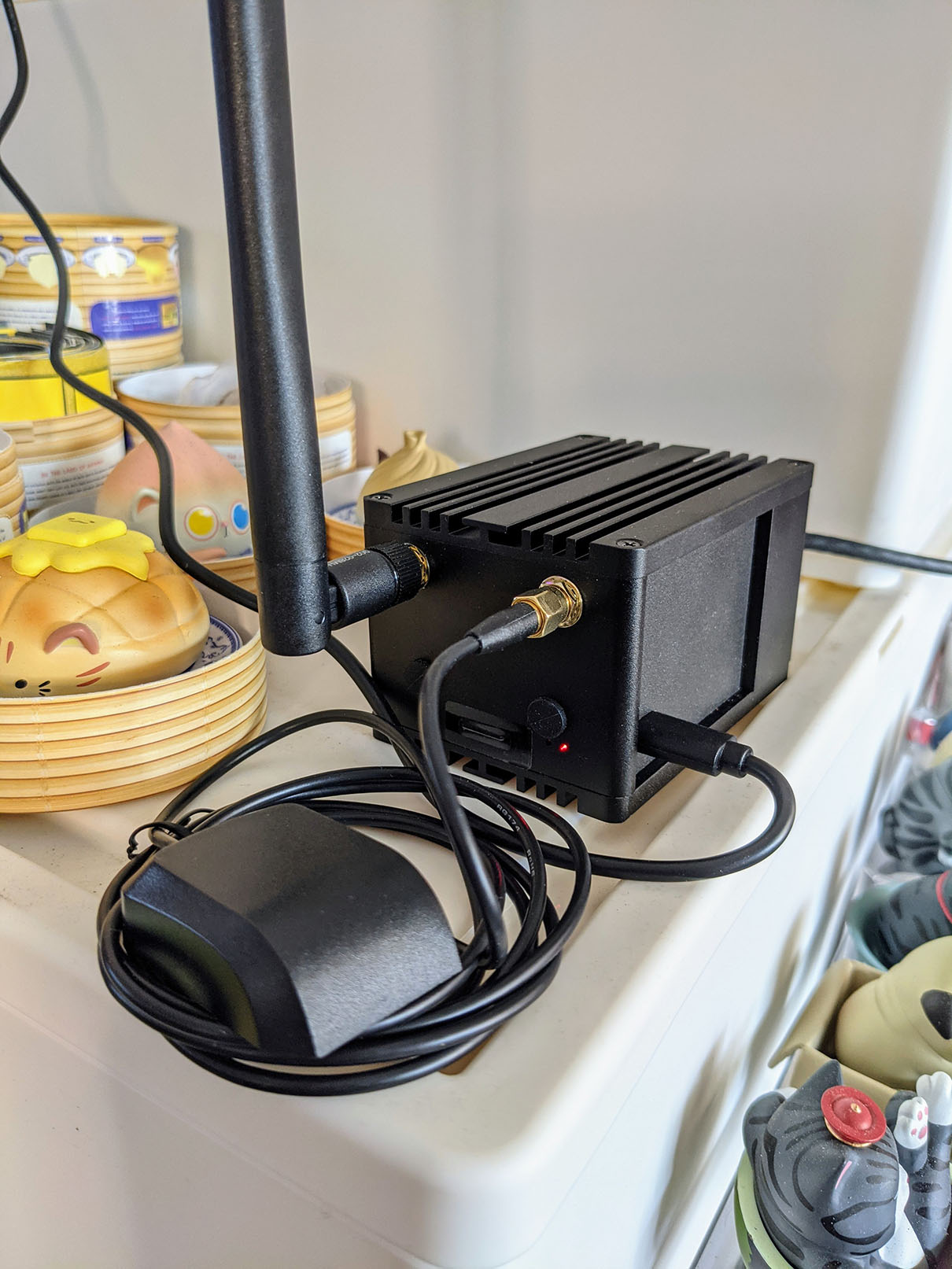
LoRa Antenna (left)
GPS Antenna (right)
(The two connectors are slightly different, so we won’t connect the wrong antenna)
The GPS Antenna will be used when we connect WisGate to The Things Network (the worldwide free-access LoRaWAN network).
WisGate D4H is shipped with the open-source ChirpStack LoRaWAN stack, preinstalled in the microSD card.
(Yep please don’t peel off the sticky tape and insert your own microSD card)
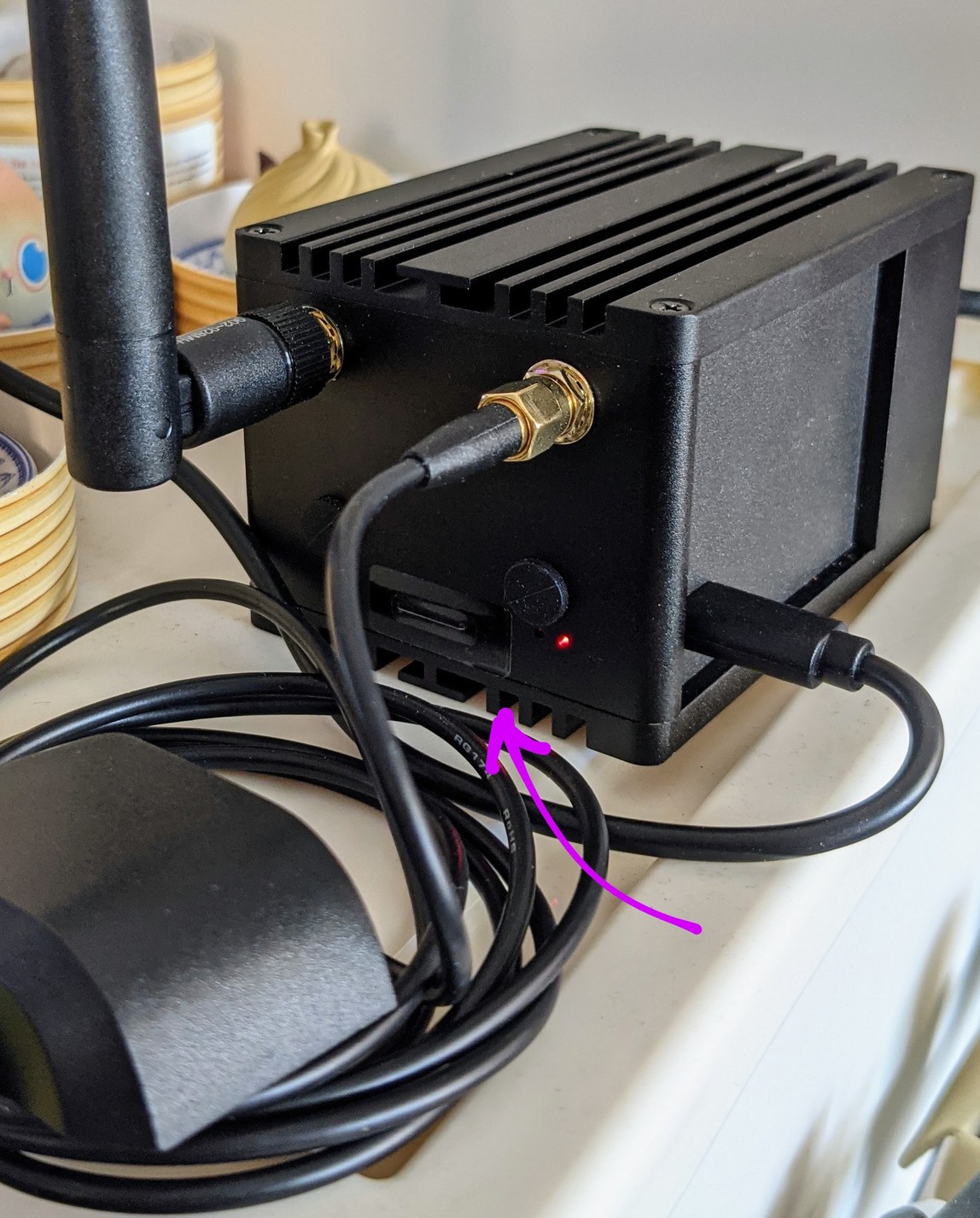
microSD Slot on WisGate D4H
Connect the LoRa Antenna and GPS Antenna to WisGate before powering on. (To prevent damage to the RF modules)
Follow the instructions here to start the WisGate box and to connect to the preinstalled ChirpStack LoRaWAN stack…
(RAK7244C is quite similar to our RAK7248 gateway)
I connected an Ethernet cable to WisGate and used SSH to configure the WiFi and LAN settings (via sudo gateway-config).
Here’s the ChirpStack web admin page that we will see…
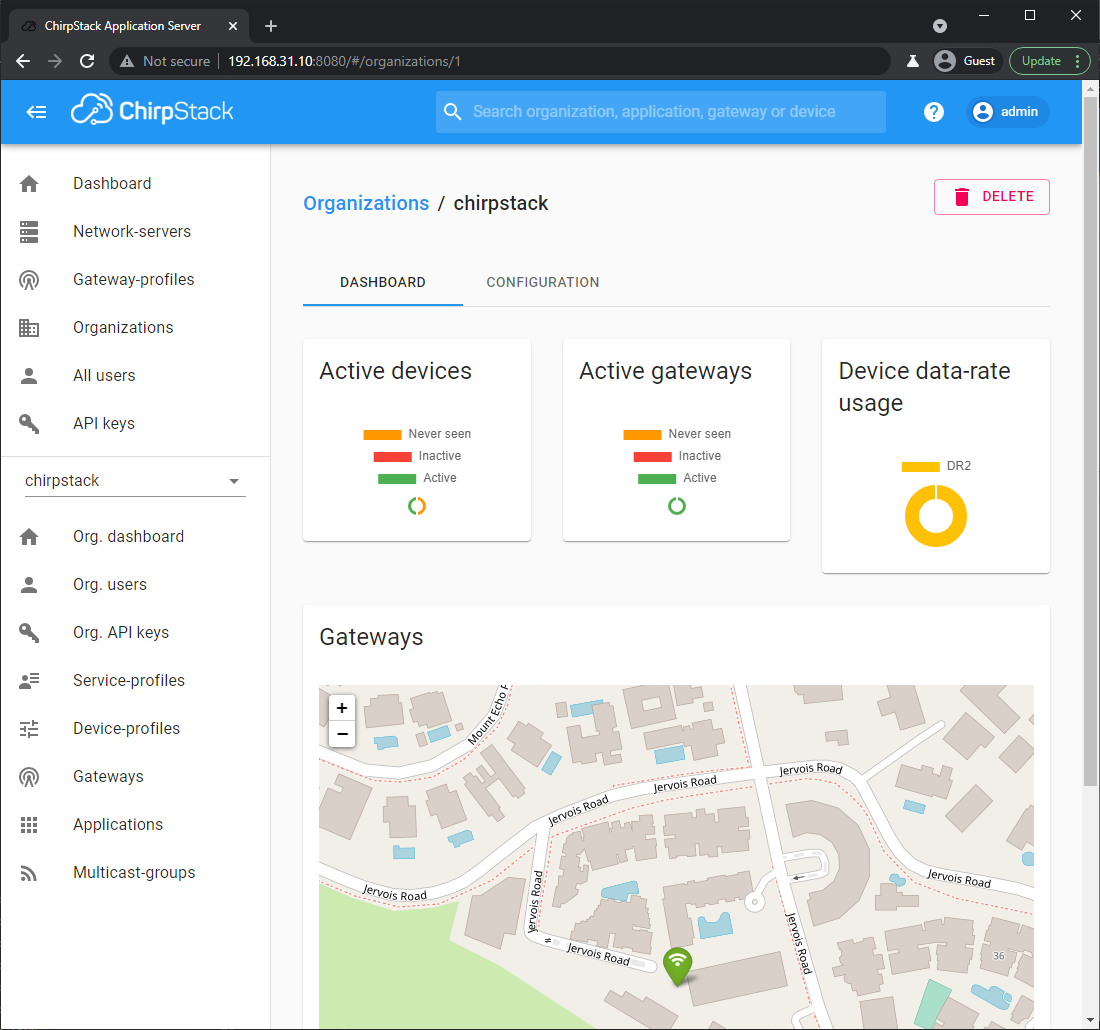
(Nope I’m nowhere near Jervois Road)
In the left bar, click Gateways to see our pre-configured LoRaWAN Gateway…
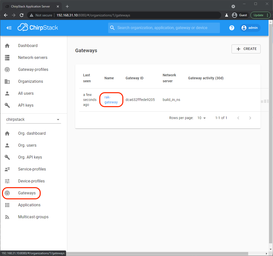
Click rak-gateway to see the Gateway Details…
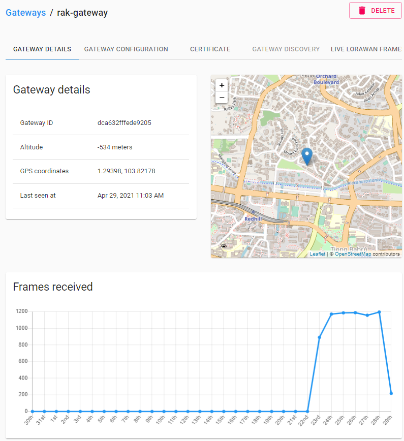
This shows that my WisGate gateway receives 1,200 LoRaWAN Packets a day from unknown LoRaWAN Devices nearby.
WisGate won’t do anything with the received LoRaWAN Packets since it’s not configured to process packets with mysterious origins.
(But we may click Live LoRaWAN Frames at top right to see the encrypted contents of the received LoRaWAN Packets)
When we allow a LoRaWAN Device to talk to our LoRaWAN Gateway, we need to set 2 things in the device…
Device EUI: A 64-bit number that uniquely identifies our LoRaWAN Device
Application Key: A 128-bit secret key that will authenticate that specific LoRaWAN Device
Here’s how we get the Device EUI and Application Key from ChirpStack…
Click Applications then app…
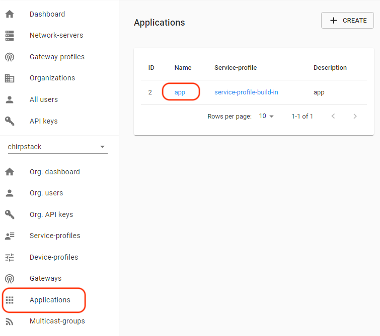
Take note of the second Device EUI (for the OTAA Device Profile)…
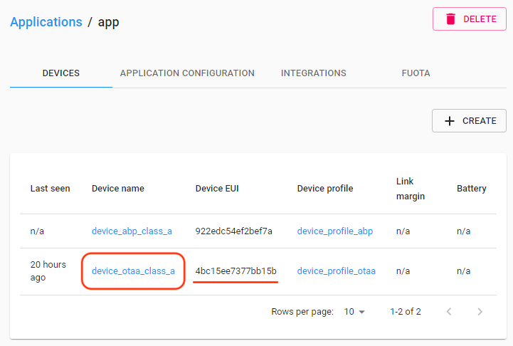
(EUI sounds like we stepped on something unpleasant… But it actually means Extended Unique Identifier)
We shall set this Device EUI in our Arduino program in a while…
uint8_t nodeDeviceEUI[8] = { 0x4b, 0xc1, 0x5e, 0xe7, 0x37, 0x7b, 0xb1, 0x5b };Click device_ptaa_class_a because we’ll be doing Over-The-Air Activation (OTAA) for our Arduino device
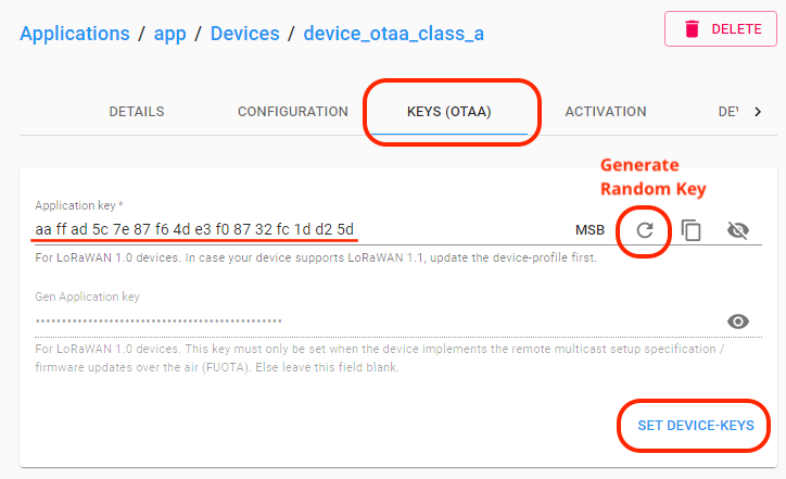
Click Keys (OTAA)
Under Application Key, click the circular arrow to generate a random key.
Take note of the generated Application Key, we shall set this in our Arduino program…
uint8_t nodeAppKey[16] = { 0xaa, 0xff, 0xad, 0x5c, 0x7e, 0x87, 0xf6, 0x4d, 0xe3, 0xf0, 0x87, 0x32, 0xfc, 0x1d, 0xd2, 0x5d };Click Set Device-Keys
We’re all set to connect our Arduino LoRaWAN Device to WisGate!
I tested WisGate with an Arduino LoRaWAN Device: RAKwireless RAK4631 WisBlock, based on Nordic nRF52840 with Semtech SX1262…
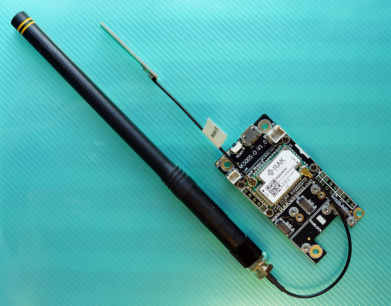
RAKwireless RAK4631 WisBlock LPWAN Module mounted on WisBlock Base Board
The Arduino source code is here…
To download the source code, enter this at the command prompt…
git clone --recursive https://github.com/lupyuen/wisblock-lorawanNote that the program requires the SX126x-Arduino Library version 2.0.0 or later.
With PlatformIO, we set the SX126x-Arduino version in platformio.ini like so…
lib_deps = beegee-tokyo/SX126x-Arduino@^2.0.0The Arduino program in this article is based on the RAKwireless LoRaWAN sample LoRaWAN_OTAA_ABP.ino
(More about LoRaWAN on WisBlock RAK4631)
Let’s look at the Arduino code in our LoRaWAN Client…
Important: Set your LoRaWAN Region in main.cpp
//  TODO: Set this to your LoRaWAN Region
LoRaMacRegion_t g_CurrentRegion = LORAMAC_REGION_AS923;
Before sending a LoRaWAN Data Packet to WisGate, we shall join our LoRaWAN Device to the LoRaWAN Network with Over-The-Air Activation (OTAA)…
//  Set to true to select Over-The-Air Activation
//  (OTAA), false for Activation By Personalisation (ABP)
bool doOTAA = true;
We won’t be using Activation By Personalisation (ABP) today.
Remember the Device EUI and Application Key from ChirpStack?
(Did we step on something?)
We paste the Device EUI and Application Key here…
//  TODO: (For OTAA Only) Set the OTAA keys. KEYS ARE MSB !!!!

//  Device EUI: Copy from ChirpStack:
//  Applications -> app -> Device EUI
uint8_t nodeDeviceEUI[8] = { 0x4b, 0xc1, 0x5e, 0xe7, 0x37, 0x7b, 0xb1, 0x5b };

//  App EUI: Not needed for ChirpStack,
//  set to default 0000000000000000
uint8_t nodeAppEUI[8] = { 0x00, 0x00, 0x00, 0x00, 0x00, 0x00, 0x00, 0x00 };

//  App Key: Copy from ChirpStack:
//  Applications -> app -> Devices ->
//  device_otaa_class_a -> Keys (OTAA) ->
//  Application Key
uint8_t nodeAppKey[16] = { 0xaa, 0xff, 0xad, 0x5c, 0x7e, 0x87, 0xf6, 0x4d, 0xe3, 0xf0, 0x87, 0x32, 0xfc, 0x1d, 0xd2, 0x5d };
The Application EUI is not used by ChirpStack, so we may set it to 0000000000000000
Since we’re not Activating By Personalisation, we may ignore this section…
//  TODO: (For ABP Only) Set the ABP keys
uint32_t nodeDevAddr = 0x260116F8;
uint8_t nodeNwsKey[16] = { 0x7E, 0xAC, 0xE2, 0x55, 0xB8, 0xA5, 0xE2, 0x69, 0x91, 0x51, 0x96, 0x06, 0x47, 0x56, 0x9D, 0x23 };
uint8_t nodeAppsKey[16] = { 0xFB, 0xAC, 0xB6, 0x47, 0xF3, 0x58, 0x45, 0xC7, 0x50, 0x7D, 0xBF, 0x16, 0x8B, 0xA8, 0xC1, 0x7C };Following the Arduino convention, our setup function shall be executed at startup: main.cpp
// At startup, we join the LoRaWAN network, in either OTAA or ABP mode
void setup() {
  ...
  //  Initialize LoRa chip
  lora_rak4630_init();

  //  Omitted: Initialize Serial for debug output
  ...

  //  Create a timer to send data to server every 20 seconds
  uint32_t err_code err_code = timers_init();
  if (err_code != 0) { return; }
Here we initialise the LoRa Transceiver (SX1262) and create a timer that will send a LoRaWAN Packet every 20 seconds.
(More about timers_init in a while)
Next we set the Device EUI, Application EUI and Application Key that will be used for joining the LoRaWAN Network…
  //  Setup the EUIs and Keys
  if (doOTAA) {
    //  Set the EUIs and Keys for OTAA
    lmh_setDevEui(nodeDeviceEUI);
    lmh_setAppEui(nodeAppEUI);
    lmh_setAppKey(nodeAppKey);
  } else {
    //  Omitted: Set the EUIs and Keys for ABP
    ...
  }
Then we initialise the LoRaWAN Client…
  //  Initialise LoRaWAN
  err_code = lmh_init(  //  lmh_init now takes 3 parameters instead of 5
    &g_lora_callbacks,  //  Callbacks
    g_lora_param_init,  //  Functions
    doOTAA,             //  Set to true for OTAA
    g_CurrentClass,     //  Class
    g_CurrentRegion     //  Region
  );
  if (err_code != 0) { return; }
(More about g_lora_callbacks in a while)
Finally we send the Join LoRaWAN Network Request to WisGate…
  //  Start Join procedure
  lmh_join();
}
What’s in g_lora_callbacks?
g_lora_callbacks contains a list of Callback Functions that will be called by the LoRaWAN Client: main.cpp
//  Structure containing LoRaWan callback functions,
//  needed for lmh_init()
static lmh_callback_t g_lora_callbacks = {
    BoardGetBatteryLevel,
    BoardGetUniqueId,
    BoardGetRandomSeed,
    lorawan_rx_handler,
    lorawan_has_joined_handler,
    lorawan_confirm_class_handler,
    lorawan_join_failed_handler
};
We shall see the Callback Functions in action soon.
What about loop, the Arduino function that will be called to do work?
Our program uses the Callback Functions to trigger actions, so we won’t be looping today.
Here’s our loop function in main.cpp
//  Nothing here for now
void loop() {
  //  Put your application tasks here, like reading of sensors,
  //  controlling actuators and other functions.
}During startup we called lmh_join to send the Join LoRaWAN Network Request to WisGate…
//  Start Join procedure
lmh_join();
When WisGate accepts the Join Request and returns an acknowledgement packet, this Callback Function will be called: main.cpp
//  Function that is called when we have joined the LoRaWAN network
void lorawan_has_joined_handler(void) {

  //  Request for a different LoRaWAN Device Class, if necessary
  lmh_error_status ret = lmh_class_request(g_CurrentClass);
Here we switch to the desired LoRaWAN Device Class (A, B or C) if necessary.
Class A is the most basic Device Class (for simple LoRaWAN sensors). Classes B and C are more sophisticated.
We have configured our LoRaWAN Client for Class A…
DeviceClass_t g_CurrentClass = CLASS_A;So lmh_class_request won’t switch our Device Class.
Our Callback Function then starts a timer that expires in 20 seconds…
  //  When we have joined the LoRaWAN network,
  //  start a 20-second timer
  if (ret == LMH_SUCCESS) {
    delay(1000);
    TimerSetValue(&appTimer, LORAWAN_APP_INTERVAL);
    TimerStart(&appTimer);
  }
}
We’ll learn more about the timer in a while. (Hint: It triggers the sending of a LoRaWAN Data Packet)
We have another Callback Function that’s called when our Join Request is rejected by WisGate: main.cpp
//  LoRa function for handling OTAA join failed
static void lorawan_join_failed_handler(void) {
  //  If we can't join the LoRaWAN network, show the error
  Serial.println("OTAA join failed!");
}
The LoRaWAN Gateway (WisGate) rejects our Join Request if the Device EUI and/or Application Key are incorrect.
In case you’re curious: WisBlock transmits this LoRaWAN Packet to WisGate when requesting to join the LoRaWAN network…
We’ll learn about the Nonce and the Message Integrity Code later.
Now that we’ve joined the LoRaWAN Network, let’s send a LoRaWAN Data Packet to WisGate!
Remember that when our Join Request succeeds, it starts a 20-second timer.
Here’s what happens 20 seconds later: main.cpp
//  Function for handling timeout event
void tx_lora_periodic_handler(void) {
  //  When the 20-second timer has expired,
  //  send a LoRaWAN Packet and restart the timer
  TimerSetValue(&appTimer, LORAWAN_APP_INTERVAL);
  TimerStart(&appTimer);
  send_lora_frame();
}
We restart the 20-second timer and call send_lora_frame to send a LoRaWAN Data Packet to WisGate.
send_lora_frame is defined in main.cpp
//  This is called when the 20-second timer expires.
//  We send a LoRaWAN Data Packet.
void send_lora_frame(void) {
  if (lmh_join_status_get() != LMH_SET) {
    //  Not joined, try again later
    return;
  }
First we verify that we have joined the LoRaWAN Network. (Because WisGate won’t process our data packet unless we’re in the network)
Then we set the packet port and populate the packet with 6 bytes: “Hello!”…
  //  Copy "Hello!" into the transmit buffer
  m_lora_app_data.port = gAppPort;  //  Set to LORAWAN_APP_PORT
  memset(m_lora_app_data.buffer, 0, LORAWAN_APP_DATA_BUFF_SIZE);
  memcpy(m_lora_app_data.buffer, "Hello!", 6);
  m_lora_app_data.buffsize = 6;
Finally we transmit the data packet to WisGate…
  //  Transmit the LoRaWAN Data Packet
  lmh_error_status error = lmh_send(
    &m_lora_app_data,  //  Data Packet
    g_CurrentConfirm   //  LMH_UNCONFIRMED_MSG: Unconfirmed Message
  );
  if (error == LMH_SUCCESS) { count++; }
  else { count_fail++; }
}
Here we’re sending an Unconfirmed LoRaWAN Message to WisGate. Which means that we don’t expect an acknowledgement from WisGate.
This is the preferred way for a low-power LoRaWAN device to transmit sensor data, since it doesn’t need to wait for the acknowledgement (and consume additional power).
(It’s OK if a LoRaWAN Data Packet gets lost due to noise or inteference… LoRaWAN sensor devices are supposed to transmit data packets periodically anyway)
What about receiving data from our LoRaWAN Gateway (WisGate)?
We haven’t configured WisGate to transmit data to our LoRaWAN Device.
But the Callback Function to handle received packets is here: main.cpp
//  Function for handling LoRaWan received data from Gateway
void lorawan_rx_handler(lmh_app_data_t *app_data) {
  //  When we receive a LoRaWAN Packet from the
  //  LoRaWAN Gateway, display it.
  //  TODO: Ensure that app_data->buffer is null-terminated.
  Serial.printf("LoRa Packet received on port %d, size:%d, rssi:%d, snr:%d, data:%s\n",
    app_data->port, app_data->buffsize, app_data->rssi, app_data->snr, app_data->buffer);
}
There’s one more Callback Function (that we’re not using) for switching the LoRaWAN Device Class: main.cpp
//  Callback Function that is called when the
//  LoRaWAN Class has been changed
void lorawan_confirm_class_handler(DeviceClass_t Class) {
  //  Informs the server that switch has occurred ASAP
  m_lora_app_data.buffsize = 0;
  m_lora_app_data.port = gAppPort;
  lmh_send(&m_lora_app_data, g_CurrentConfirm);
}
How did we initialise the 20-second timer?
During startup, the setup function calls timers_init to initialise the timer: main.cpp
//  Initialise the timer
uint32_t timers_init(void) {
  TimerInit(&appTimer, tx_lora_periodic_handler);
  return 0;
}Let’s run the Arduino program on WisBlock and watch what happens in the Arduino Log!
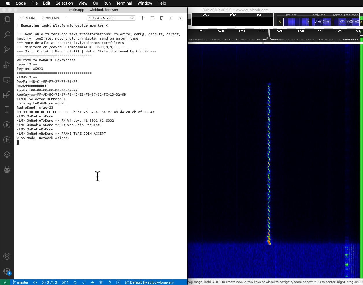
Our Arduino program starts by reminding us of the Over-The-Air Activation (OTAA) configuration: Device EUI, Application EUI (unused) and Application Key…
OTAA
DevEui=4B-C1-5E-E7-37-7B-B1-5B
DevAdd=00000000
AppEui=00-00-00-00-00-00-00-00
AppKey=AA-FF-AD-5C-7E-87-F6-4D-E3-F0-87-32-FC-1D-D2-5D
(Device Address will be assigned by WisGate when we join the LoRaWAN Network)
We transmit the Join Network Request to WisGate…
Selected subband 1
Joining LoRaWAN network...
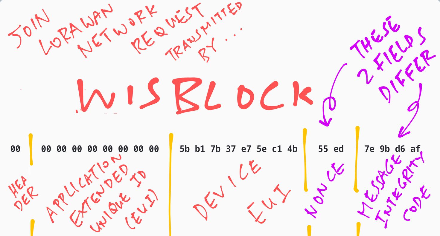
RadioSend: 00 00 00 00 00 00 00 00 00 5b b1 7b 37 e7 5e c1 4b 55 ed 7e 9b d6 af
OnRadioTxDoneThe Join Network Request contains these fields…
But the Application Key is missing from the Join Network Request!?
Yep! We’ll learn why in a while.
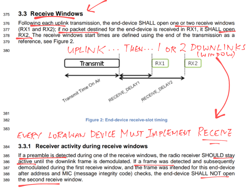
To conserve power, LoRaWAN Devices (Class A) don’t receive packets all the time.
We listen for incoming packets (for a brief moment) only after we transmit a packet…
OnRadioTxDone => RX Windows #1 5002 #2 6002
OnRadioTxDone => TX was Join Request
We’ve just transmitted a packet (Join Network Request), so we listen for an incoming packet. (Hopefully, the Join Network Response from WisGate)
The LoRaWAN Specification actually defines Two Receive Windows. Which means that we listen twice (very briefly) for incoming packets, after sending every packet…
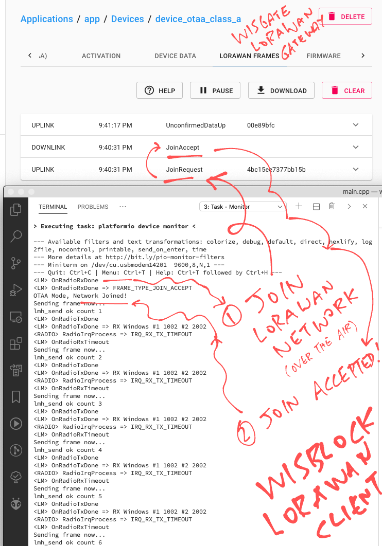
And indeed, we receive the Join Network Accepted Response from WisGate…
OnRadioRxDone
OnRadioRxDone => FRAME_TYPE_JOIN_ACCEPT
OTAA Mode, Network Joined!
The LoRaWAN Spec says we don’t open the Second Receive Window if we receive a packet in the First Receive Window.
So… We’re good!
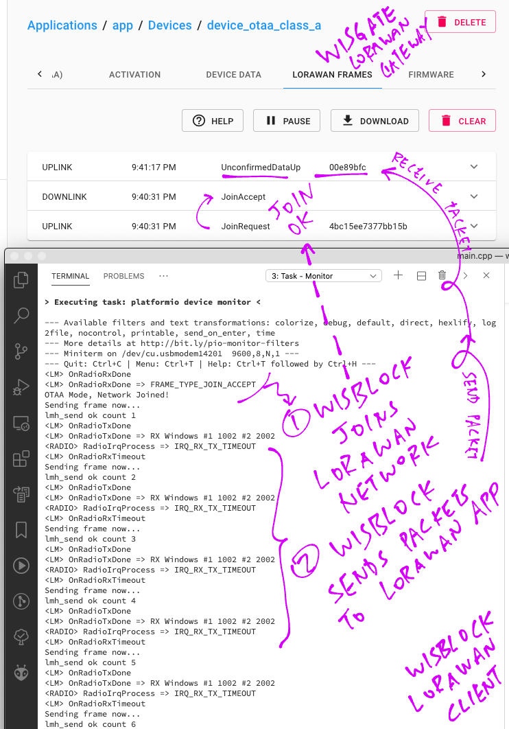
20 seconds later we transmit our first data packet (“Hello!”)…
Sending frame now...
RadioSend: 40 3c 59 7a 00 80 00 00 02 17 77 31 fd 99 86 8f 4f cc ef
lmh_send ok count 1
OnRadioTxDone
Once again we open the Two Receive Windows…
OnRadioTxDone => RX Windows #1 1002 #2 2002
RadioIrqProcess => IRQ_RX_TX_TIMEOUT
OnRadioRxTimeout
We haven’t configured WisGate to respond to our data packet. (Remember that we’re sending Unconfirmed LoRaWAN Messages… No ack needed)
So we get a Receive Timeout. Which is expected.
20 seconds later we transmit our second data packet…
Sending frame now...
RadioSend: 40 3c 59 7a 00 80 01 00 02 0b 1f 7e 4d e1 94 c9 16 fa ea
lmh_send ok count 2
OnRadioTxDone
We open the Two Receive Windows and we get a Receive Timeout, which is OK…
OnRadioTxDone => RX Windows #1 1002 #2 2002
RadioIrqProcess => IRQ_RX_TX_TIMEOUT
OnRadioRxTimeoutLet’s head back to ChirpStack on our WisGate LoRaWAN Gateway, to observe the LoRaWAN Packets received from our Arduino Device (WisBlock)…
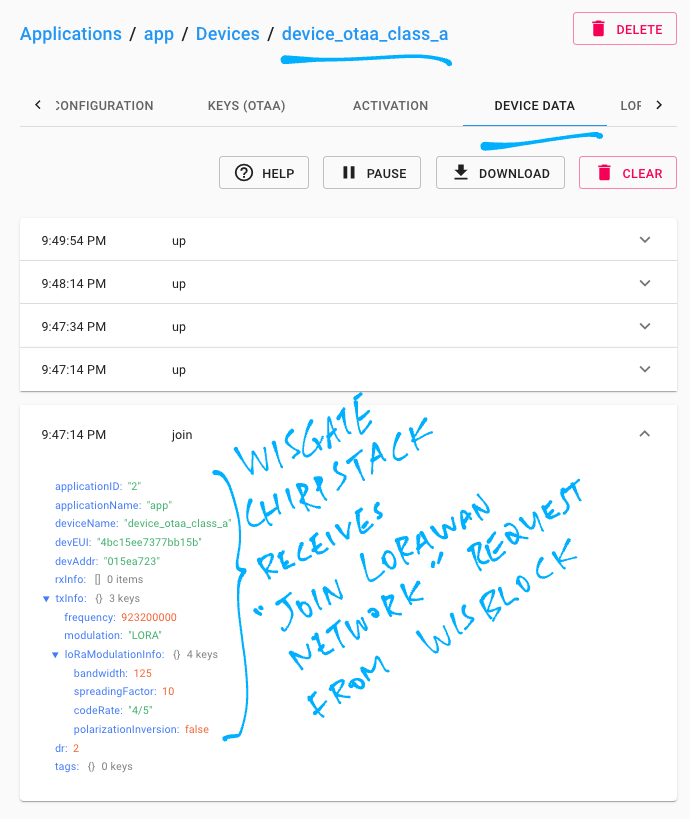
In ChirpStack, click Applications → app → device_otaa_class_a → Device Data
Restart our Arduino LoRaWAN Device (WisBlock)
The Join Network Request appears…
20 seconds later the Data Packet appears…
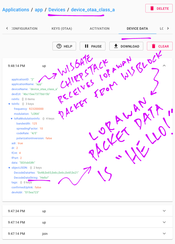
DecodedDataString says “Hello!”
We may now configure ChirpStack to do something useful with the received packets, like publish them over MQTT, HTTP, …
Click this link…
Then click the Menu (top left) and Integrations
If our packets don’t appear in ChirpStack, here are a couple of things to check…
To troubleshoot LoRaWAN problems, we may inspect the Raw LoRaWAN Packets received by our LoRaWAN Gateway (WisGate).
In ChirpStack there are two ways do this…
Click Gateways → rak-gateway → Live LoRaWAN Frames
This shows ALL LoRaWAN Packets received, even from unknown devices.
(The packet data is encrypted, so we won’t be able to read other people’s messages)
Or click Applications → app → device_otaa_class_a → LoRaWAN Frames
This only shows LoRaWAN Packets from identified devices.
Here’s the Raw Packet for Join Network Request…
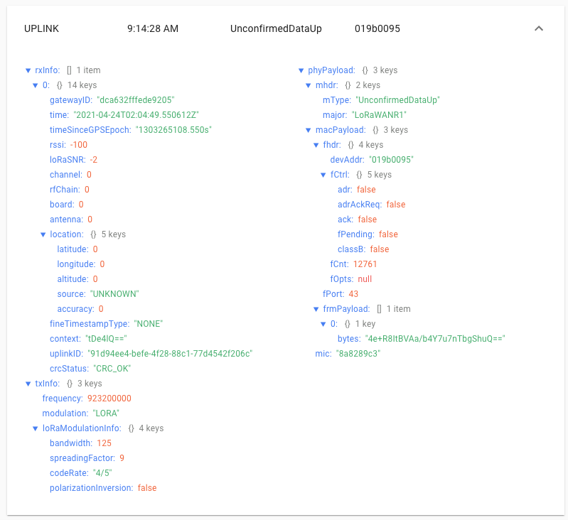
And here’s the Raw Data Packet…
This is the mystery LoRaWAN Packet that my LoRaWAN Gateway (WisGate) receives every minute (with encrypted contents)…
SSH to WisGate and look at the Linux System Log while our LoRaWAN Device is transmitting packets…
tail -f /var/log/syslogSometimes it’s helpful to scan the log for Message Integrity Code errors (“invalid MIC”)…
grep MIC /var/log/syslog

Apr 28 04:02:05 rak-gateway
chirpstack-application-server[568]:
time="2021-04-28T04:02:05+01:00"
level=error
msg="invalid MIC"
dev_eui=4bc15ee7377bb15b
type=DATA_UP_MIC
Also for Nonce Errors (“validate dev-nonce error”)…
grep nonce /var/log/syslog

Apr 28 04:02:41 rak-gateway chirpstack-application-server[568]:
time="2021-04-28T04:02:41+01:00"
level=error
msg="validate dev-nonce error"
dev_eui=4bc15ee7377bb15b
type=OTAA
Another way to check for Nonce Errors: Click…
Applications → app → device_otaa_class_a → Device Data
Look for “validate dev-nonce error”…
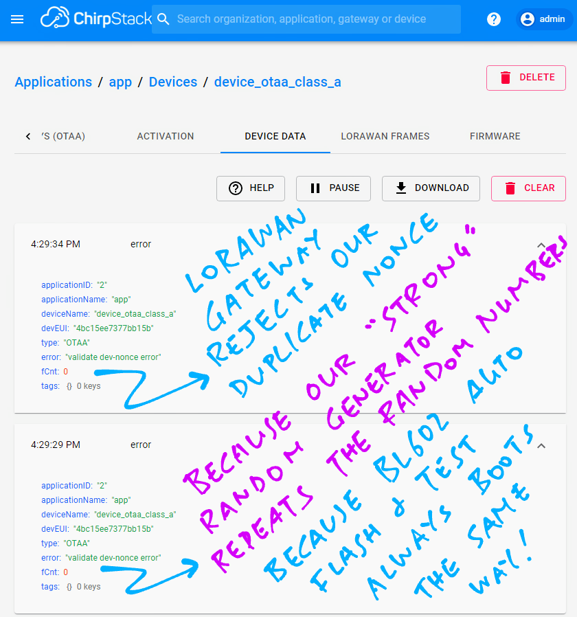
We’ll talk about Message Integrity Code and Nonce in a while.
To verify the actual frequency that our LoRaWAN Device is transmitting on, we may sniff the airwaves with a Software Defined Radio.
Or use a Spectrum Analyser like RF Explorer. (See this)
Let’s talk about Software Defined Radio…
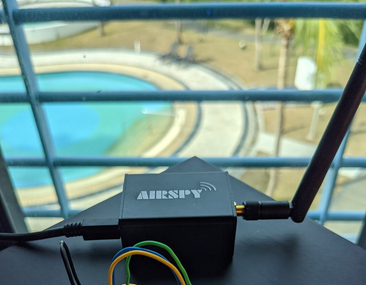
A Software Defined Radio (SDR) is a USB gadget that scans the airwaves (for a range of frequencies) and feeds the data to our computer for processing.
I use the Airspy R2 SDR to sniff the airwaves and verify that our LoRaWAN Device is transmitting at the right frequency with sufficient power…
Here’s the Join Network Request transmitted by WisBlock to WisGate, captured by Airspy SDR and visualised with Cubic SDR…
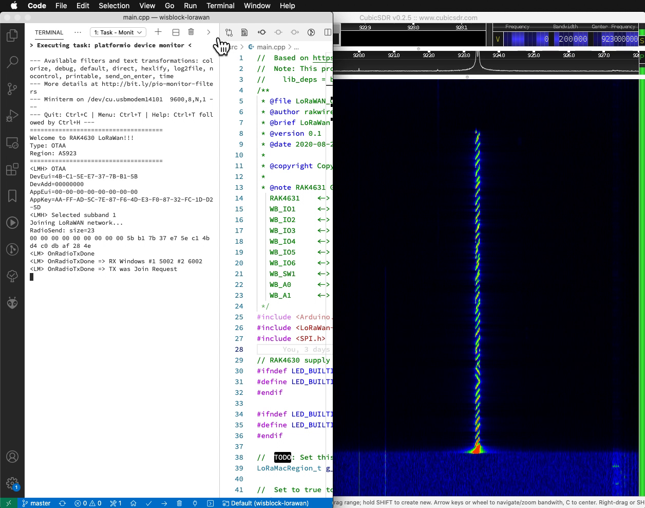
And here’s the Join Network Response returned by WisGate to WisBlock…
(Our SDR is located near WisBlock, hence the WisGate signal looks slightly weaker)
LoRaWAN Packets have a distinct cross-hatch pattern known as the LoRa Chirp. By transmitting packets in this unique chirping pattern, LoRa ensures that packets will be delivered over long distances in spite of the noise and interference.
I’m no Security Expert… But lemme attempt to explain the high-level bits of LoRaWAN Security to the best of my understanding 🙏
Let’s start by looking at the Join Network Request transmitted by our LoRaWAN Device (WisBlock) to our LoRaWAN Gateway (WisGate). And understand why it’s secure…
There are 5 parts in the request…
Header (1 byte): Identifies this LoRaWAN Packet as a Join Network Request
Application EUI (8 bytes): Unused
Device EUI (8 bytes): Uniquely identifies our LoRaWAN Device. (The bytes are flipped)
Nonce (2 bytes): We’ll explain in a while
Message Integrity Code (4 bytes): We’ll explain now
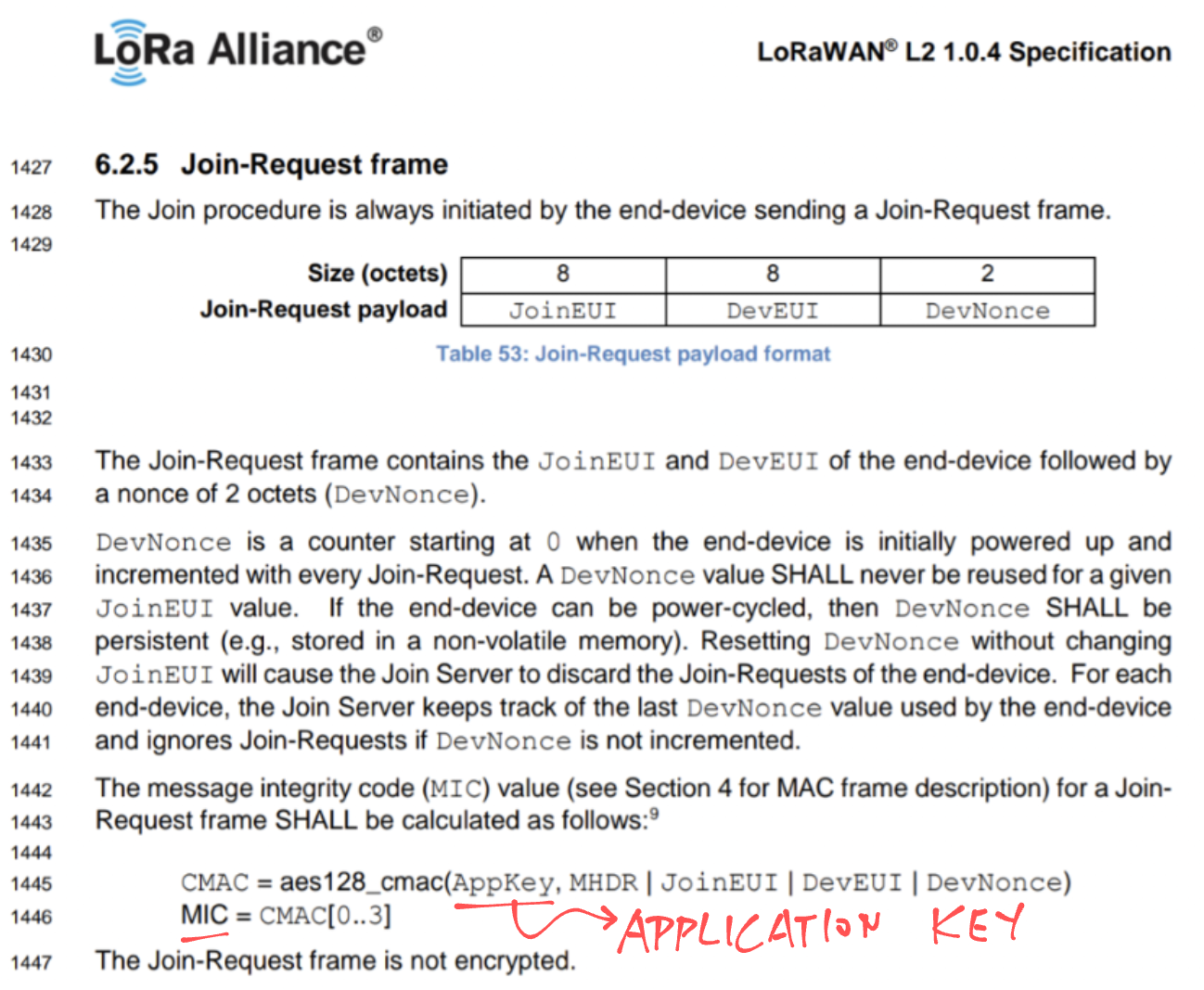
Why isn’t the Application Key inside the Join Network Request?
Because the Application Key is a Secret Key. It should never be revealed to others, otherwise our gateway will accept Join Network Requests from unauthorised devices.
Instead we use the Application Key to compute a Message Authentication Code (AES-128 CMAC). And we transmit the first 4 bytes of the authentication code as the Message Integrity Code.
According to the LoRaWAN Spec, the Message Authentication Code (for the Join Network Request) is computed with these input values…
Application Key
Header
Application EUI
Device EUI
Nonce (We’ll explain in the next section)
What happens when we transmit an invalid Message Integrity Code?
Our LoRaWAN Gateway (ChirpStack on WisGate) will reject LoRaWAN Packets with invalid Message Integrity Codes.
To see Message Integrity Code errors, SSH to our LoRaWAN Gateway and search for “invalid MIC”…
grep MIC /var/log/syslog

Apr 28 04:02:05 rak-gateway
chirpstack-application-server[568]:
time="2021-04-28T04:02:05+01:00"
level=error
msg="invalid MIC"
dev_eui=4bc15ee7377bb15b
type=DATA_UP_MIC

Apr 28 04:02:05 rak-gateway
chirpstack-network-server[1378]:
time="2021-04-28T04:02:05+01:00"
level=error
msg="uplink: processing uplink frame error"
ctx_id=0ccd1478-3b79-4ded-9e26-a28e4c143edc
error="get device-session error: invalid MIC"There isn’t a Timestamp in the request. Could someone record and replay the Join Network Request?
That’s why we have the Nonce: A 16-bit number that’s only used once and never reused by our LoRaWAN Device.
The Nonce appears in the Join Network Request, and it’s also used for computing the Message Integrity Code.
What happens when we replay a Join Network Request?
Our LoRaWAN Gateway (ChirpStack on WisGate) will reject Join Network Requests that have a reused Nonce.
(Yep the gateway will remember the Nonces from previous requests)
To see Nonce errors, SSH to our LoRaWAN Gateway and search for “validate dev-nonce error”…
grep nonce /var/log/syslog

Apr 28 04:02:41 rak-gateway chirpstack-application-server[568]:
time="2021-04-28T04:02:41+01:00"
level=error
msg="validate dev-nonce error"
dev_eui=4bc15ee7377bb15b
type=OTAA

Apr 28 04:02:41 rak-gateway chirpstack-network-server[1378]:
time="2021-04-28T04:02:41+01:00"
level=error
msg="uplink: processing uplink frame error" ctx_id=01ae296e-8ce1-449a-83cc-fb0771059d89
error="validate dev-nonce error: object already exists"
Nonce errors will also appear in ChirpStack. Click…
Applications → app → device_otaa_class_a → Device Data
Look for “validate dev-nonce error”…
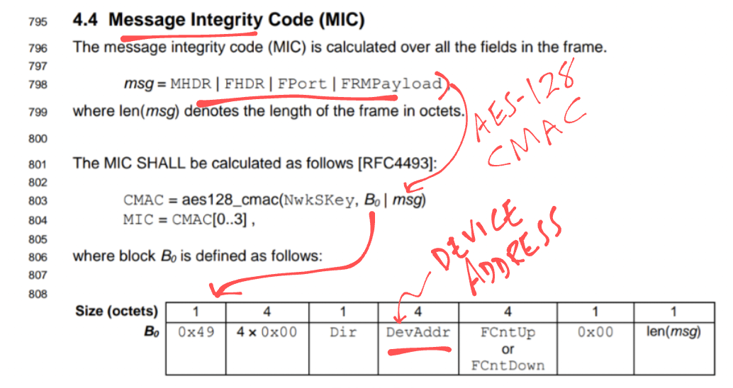
Here’s the LoRaWAN Spec for the Nonce and Message Integrity Code…
For other LoRaWAN Packets (besides the Join Network Request), the Message Integrity Code is computed differently…
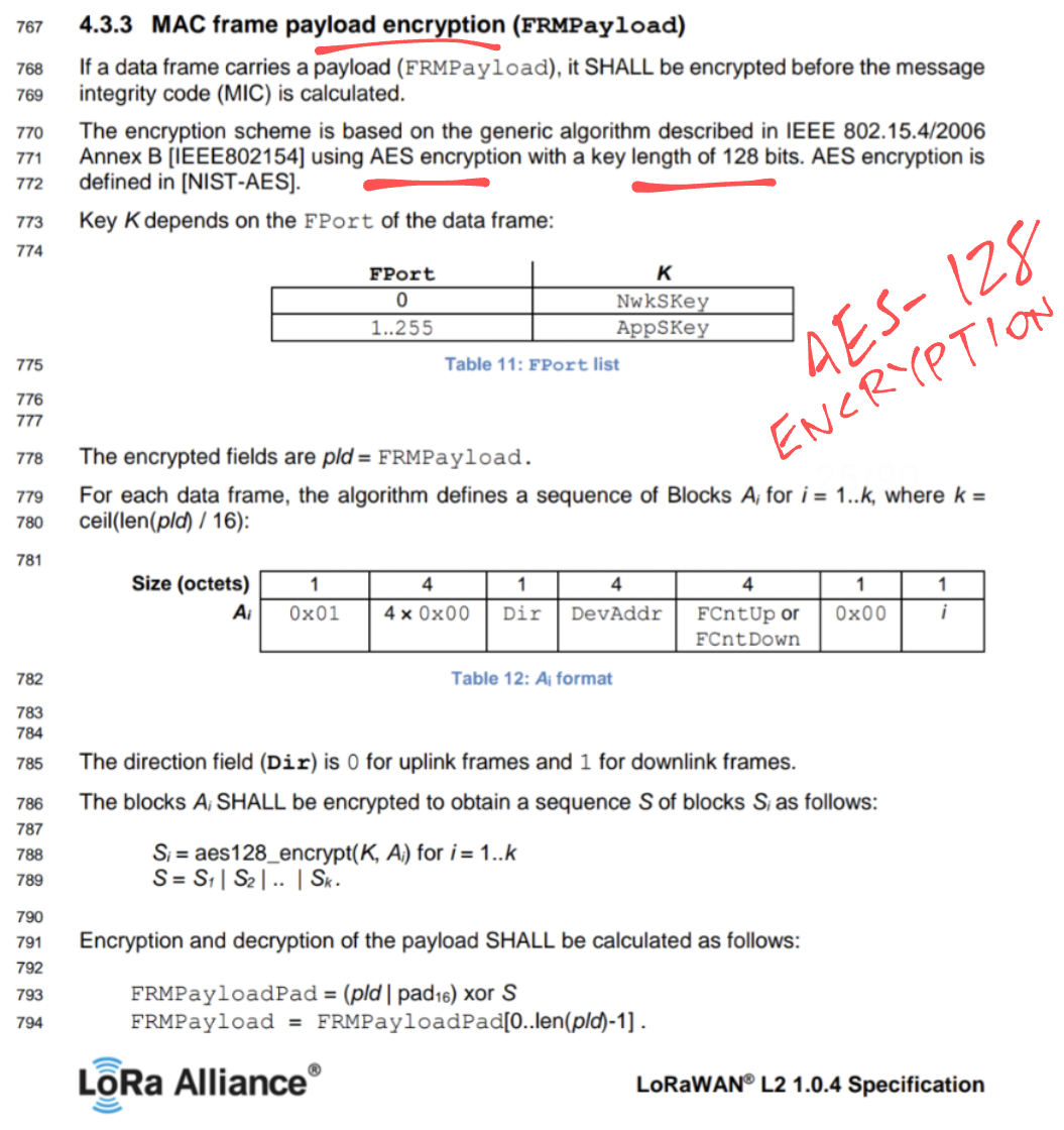
LoRaWAN Payloads are encrypted with AES-128, says the LoRaWAN Spec…
And that’s the limit of my security know-how 🙁
To learn more about LoRaWAN Security, I recommend this article…
Pine64’s upcoming PineDio LoRa Gateway works very much like WisGate, here’s my hands-on experience…
To learn about configuring WisGate for The Things Network, check out this article…
This has been a fun experience for me, diving deep into LoRaWAN with the RAKwireless WisGate LoRaWAN Gateway… My first time using LoRaWAN!
I hope you find this article useful. Now that I know some LoRaWAN, I’m heading back to PineCone BL602 to finish what I started…
And then to PineDio Stack BL604…
Many Thanks to my GitHub Sponsors for supporting my work! This article wouldn’t have been possible without your support.
Got a question, comment or suggestion? Create an Issue or submit a Pull Request here…
lupyuen.github.io/src/wisgate.md
To log transmitted packets in our Arduino program, modify this source file…
.pio/libdeps/wiscore_rak4631/SX126x-Arduino/src/mac/LoRaMac.cppInsert the section marked below…
LoRaMacStatus_t SendFrameOnChannel(uint8_t channel)
{
    TxConfigParams_t txConfig;
    int8_t txPower = 0;

    txConfig.Channel = channel;
    txConfig.Datarate = LoRaMacParams.ChannelsDatarate;
    txConfig.TxPower = LoRaMacParams.ChannelsTxPower;
    txConfig.MaxEirp = LoRaMacParams.MaxEirp;
    txConfig.AntennaGain = LoRaMacParams.AntennaGain;
    txConfig.PktLen = LoRaMacBufferPktLen;

    // If we are connecting to a single channel gateway we use always the same predefined channel and datarate
    if (singleChannelGateway)
    {
        txConfig.Channel = singleChannelSelected;
        txConfig.Datarate = singleChannelDatarate;
    }

    RegionTxConfig(LoRaMacRegion, &txConfig, &txPower, &TxTimeOnAir);

    MlmeConfirm.Status = LORAMAC_EVENT_INFO_STATUS_ERROR;
    McpsConfirm.Status = LORAMAC_EVENT_INFO_STATUS_ERROR;
    McpsConfirm.Datarate = LoRaMacParams.ChannelsDatarate;
    McpsConfirm.TxPower = txPower;

    // Store the time on air
    McpsConfirm.TxTimeOnAir = TxTimeOnAir;
    MlmeConfirm.TxTimeOnAir = TxTimeOnAir;

    // Starts the MAC layer status check timer
    TimerSetValue(&MacStateCheckTimer, MAC_STATE_CHECK_TIMEOUT);
    TimerStart(&MacStateCheckTimer);

    if (IsLoRaMacNetworkJoined != JOIN_OK)
    {
        JoinRequestTrials++;
    }

    //////////////// INSERT THIS CODE

    // To replay a Join Network Request...
    // if (LoRaMacBuffer[0] == 0) {
    // 	static uint8_t replay[] = {0x00, 0x00, 0x00, 0x00, 0x00, 0x00, 0x00, 0x00, 0x00, 0x5b, 0xb1, 0x7b, 0x37, 0xe7, 0x5e, 0xc1, 0x4b, 0x67, 0xaa, 0xbb, 0x07, 0x70, 0x7d};
    // 	memcpy(LoRaMacBuffer, replay, LoRaMacBufferPktLen);
    // }

    // To dump transmitted packets...
    printf("RadioSend: size=%d, channel=%d, datarate=%d, txpower=%d, maxeirp=%d, antennagain=%d\r\n", (int) LoRaMacBufferPktLen, (int) txConfig.Channel, (int) txConfig.Datarate, (int) txConfig.TxPower, (int) txConfig.MaxEirp, (int) txConfig.AntennaGain);
    for (int i = 0; i < LoRaMacBufferPktLen; i++) {
        printf("%02x ", LoRaMacBuffer[i]);
    }
    printf("\r\n");

    //////////////// END OF INSERTION

    // Send now
    Radio.Send(LoRaMacBuffer, LoRaMacBufferPktLen);

    LoRaMacState |= LORAMAC_TX_RUNNING;

    return LORAMAC_STATUS_OK;
}