📝 11 Mar 2021
Suppose we’ve created a wireless LoRa Sensor.
(Maybe a sensor that monitors the soil moisture in our home garden)
Is there a simple way to check…
Whether our LoRa Sensor is transmitting packets correctly…
And what’s the Wireless Range of our LoRa Sensor?
Today we shall install RAKwireless WisBlock to check the packets transmitted by our LoRa Sensor.
We’ll be testing WisBlock with a LoRa Sensor built with the PineCone BL602 RISC-V Board…
Many thanks to RAKwireless for providing the WisBlock Connected Box!
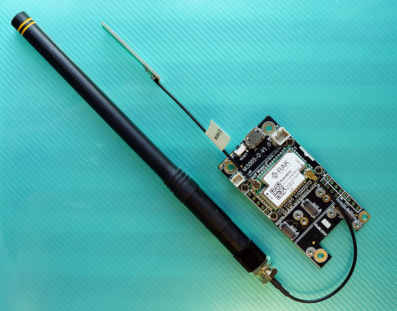
RAKwireless WisBlock LPWAN Module mounted on WisBlock Base Board
Connect the following components according to the pic above…
WisBlock LPWAN Module: This is the Nordic nRF52840 Microcontroller with Semtech SX1262 LoRa Transceiver. (More about this)
Mount the LPWAN Module onto the WisBlock Base Board.
(The LPWAN Module is already mounted when get the WisBlock Connected Box)
WisBlock Base Board: This provides power to the LPWAN Module and exposes the USB and I/O ports. (More about this)
The LPWAN Module should be mounted on the Base Board.
LoRa Antenna: Connect the LoRa Antenna to the LPWAN Module.
(That’s the black rod. Use the Antenna Adapter Cable)
Bluetooth LE Antenna: Connect the Bluetooth LE Antenna to the LPWAN Module.
(The stringy flappy thingy)
The above components are shipped in the WisBlock Connected Box. (Which includes many more goodies!)
For the LPWAN Module, be sure to choose the right LoRa Frequency for your region…
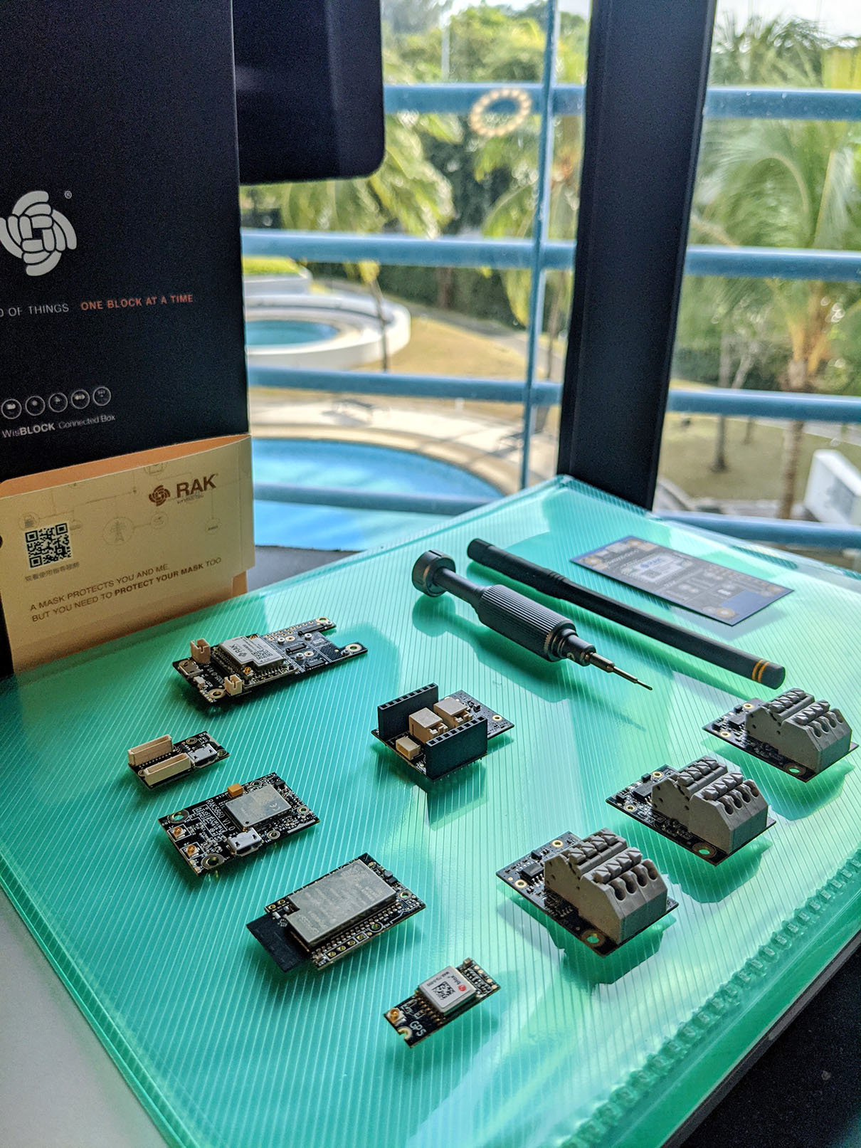
RAKwireless WisBlock Connected Box
WisBlock is based on the powerful nRF52840 Microcontroller. Do we program it with FreeRTOS, Zephyr, Mynewt, …?
Here’s the surprisingly thing about WisBlock… We program WisBlock with Arduino! (C++)
The Arduino Drivers for Semtech SX1262 will work fine with WisBlock.
(Most other Arduino Drivers will run fine too!)
But Arduino doesn’t support Multitasking… No?
Here’s another surprisingly thing about WisBlock… WisBlock Arduino is based on FreeRTOS!
(Technically: WisBlock is based on the Adafruit nRF52 Arduino Framework, which is based on FreeRTOS. See this)
So Multitasking Firmware coded in FreeRTOS will run fine on WisBlock.
Arduino programs will generally expose these two functions…
Setup Function that’s run when the micrcontroller starts up
Loop Function that’s called repeatedly to handle events
Let’s see what happens inside the Setup and Loop Functions for our WisBlock LoRa Receiver.
In the Setup Function, we start by initialising the LoRa Module and the Serial Port: main.cpp
//  Setup Function is called upon startup
void setup() {

    //  Initialize the LoRa Module
    lora_rak4630_init();

    //  Initialize the Serial Port for debug output
    Serial.begin(115200);
    while (!Serial) { delay(10); }
Next we set the Callback Functions that will be triggered by the LoRa Driver…
    //  Set the LoRa Callback Functions
    RadioEvents.TxDone    = NULL;
    RadioEvents.RxDone    = OnRxDone;
    RadioEvents.TxTimeout = NULL;
    RadioEvents.RxTimeout = OnRxTimeout;
    RadioEvents.RxError   = OnRxError;
    RadioEvents.CadDone   = NULL;
The Callback Functions are…
OnRxDone: Called by the LoRa Driver when it receives a LoRa Packet
(We shall print the contents of the LoRa Packet)
OnRxTimeout: Called by the LoRa Driver when it hasn’t received a LoRa Packet within a timeout duration.
(RX_TIMEOUT_VALUE, which is 3 seconds)
OnRxError: Called by the LoRa Driver when it has received a corrupted packet.
(Probably due to interference or weak signal)
RadioEvents has been defined earlier like so…
//  Callback Functions for LoRa Events
static RadioEvents_t RadioEvents;
We initialise the LoRa Transceiver and register the Callback Functions with the LoRa Driver…
    //  Initialize the LoRa Transceiver
    Radio.Init(&RadioEvents);
We set the LoRa Frequency (434, 780, 868, 915 or 923 MHz) which depends on your region. (More about this in a while)
    //  Set the LoRa Frequency
    Radio.SetChannel(RF_FREQUENCY);
Then we set the LoRa Parameters for receiving the packets…
    //  Configure the LoRa Transceiver for receiving messages
    Radio.SetRxConfig(
        MODEM_LORA,
        LORA_BANDWIDTH,
        LORA_SPREADING_FACTOR,
        LORA_CODINGRATE,
        0,        //  AFC bandwidth: Unused with LoRa
        LORA_PREAMBLE_LENGTH,
        LORA_SYMBOL_TIMEOUT,
        LORA_FIX_LENGTH_PAYLOAD_ON,
        0,        //  Fixed payload length: N/A
        true,     //  CRC enabled
        0,        //  Frequency hopping disabled
        0,        //  Hop period: N/A
        LORA_IQ_INVERSION_ON,
        true      //  Continuous receive mode
    );
These must match the LoRa Parameters used in our LoRa Transmitter. (More about this later)
Finally we ask the LoRa Driver to start receiving LoRa Packets…
    //  Start receiving LoRa packets
    Radio.Rx(RX_TIMEOUT_VALUE);
}
The timeout value RX_TIMEOUT_VALUE is set to 3 seconds.
After calling the Setup Function, the Arduino Framework calls the Loop Function repeatedly to handle events.
At the start of the Loop Function, we handle the Callback Functions triggered by the LoRa Transceiver: main.cpp
//  Loop Function is called repeatedly to handle events
void loop() {
    //  Handle Radio events
    Radio.IrqProcess();
Finally we yield control to FreeRTOS, to allow other tasks to run…
    //  We are on FreeRTOS, give other tasks a chance to run
    delay(100);
    yield();
}
The code in this article is based on the (now obsolete) WisBlock LoRa Receiver Example: LoRaP2P_RX.ino
(And it bears a striking resemblance to the code for PineCone BL602 LoRa)
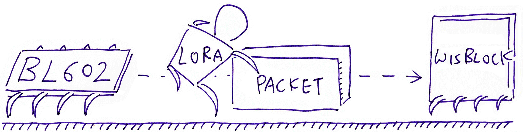
LoRa pushing 64-byte packets from BL602 to WisBlock
We have prepped our WisBlock LoRa Transceiver to receive packets… Let’s watch how we handle the received LoRa Packets.
The Callback Function OnRxDone is triggered by the LoRa Driver whenever a LoRa Packet has been received successfully.
First we show the Timestamp (in seconds), Signal Strength and Signal To Noise Ratio: main.cpp
//  Callback Function to be executed on Packet Received event
void OnRxDone(uint8_t *payload, uint16_t size, int16_t rssi, int8_t snr) {
    //  We have received a valid packet. Show the timestamp in seconds.
    Serial.printf("OnRxDone: Timestamp=%d, ", millis() / 1000);

    //  Show the signal strength, signal to noise ratio
    Serial.printf("RssiValue=%d dBm, SnrValue=%d, Data=", rssi, snr);
We pause a short while and copy the received packet into our 64-byte buffer RcvBuffer…
    delay(10);
    memcpy(RcvBuffer, payload, size);
RcvBuffer is defined as a 64-byte buffer…
    //  Buffer for received LoRa Packet
    static uint8_t RcvBuffer[64];
Then we display the 64 bytes received…
    //  Show the packet received
    for (int idx = 0; idx < size; idx++) {
        Serial.printf("%02X ", RcvBuffer[idx]);
    }
    Serial.println("");
Finally we ask the LoRa Driver to receive the next packet…
    //  Receive the next packet
    Radio.Rx(RX_TIMEOUT_VALUE);
}
The timeout value RX_TIMEOUT_VALUE is set to 3 seconds.
Check out the log of received packets
Looks kinda crowded… We show everything in a single line?
Yes because we’ll be copying and pasting the lines into a spreadsheet for analysis.
This way it’s easier to scrub the data.
We’ve set the Receive Timeout to 3 seconds. What happens if we don’t receive a LoRa Packet in 3 seconds?
The LoRa Driver will trigger our OnRxTimeout Callback Function: main.cpp
//  Callback Function to be executed on Receive Timeout event
void OnRxTimeout(void) {
    //  We haven't received a packet during the timeout period.
    //  We disable the timeout message because it makes the log much longer.
    //  Serial.println("OnRxTimeout");
We don’t do much in OnRxTimeout because it’s perfectly OK to time out… We don’t expect a LoRa Packet every 3 seconds.
All we do in OnRxTimeout is to ask the LoRa Driver to receive the next packet…
    //  Receive the next packet. Timeout in 3 seconds.
    Radio.Rx(RX_TIMEOUT_VALUE);
}The LoRa Driver triggers our Callback Function OnRxError whenever it receives a corrupted LoRa Packet.
(Likely due to interference or weak signal. Or an itchy finger powered off the LoRa Transceiver during transmission)
We show the Timestamp (in seconds) for troubleshooting and analysis: main.cpp
//  Callback Function to be executed on Receive Error event
void OnRxError(void) {
    //  We have received a corrupted packet, probably due to weak signal.
    //  Show the timestamp in seconds.
    Serial.printf("OnRxError: Timestamp=%d\n", millis() / 1000);
And we ask the LoRa Driver to receive the next packet…
    //  Receive the next packet. Timeout in 3 seconds.
    Radio.Rx(RX_TIMEOUT_VALUE);
}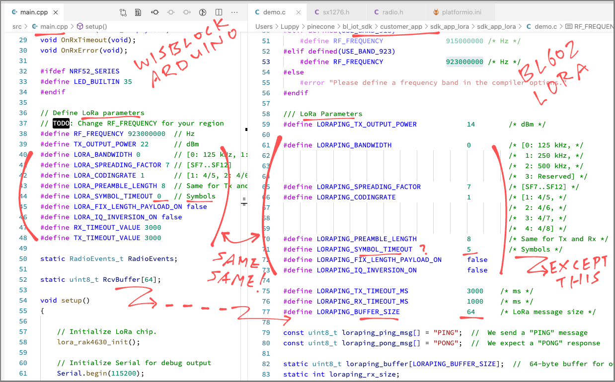
LoRa Parameters in WisBlock LoRa Receiver must match those in the LoRa Transmitter (PineCone BL602)
Our WisBlock LoRa Receiver must be configured with the same settings as the LoRa Transmitter… Or we won’t receive any LoRa Packets!
Here’s the LoRa Configuration for our WisBlock LoRa Receiver: main.cpp
// Define LoRa parameters. To receive LoRa packets from BL602, sync the parameters with
// https://github.com/lupyuen/bl_iot_sdk/blob/lora/customer_app/sdk_app_lora/sdk_app_lora/demo.c#L41-L77
// TODO: Change RF_FREQUENCY for your region
#define RF_FREQUENCY          923000000	// Hz
#define TX_OUTPUT_POWER       22		// dBm
#define LORA_BANDWIDTH        0		    // [0: 125 kHz, 1: 250 kHz, 2: 500 kHz, 3: Reserved]
#define LORA_SPREADING_FACTOR 7         // [SF7..SF12]
#define LORA_CODINGRATE       1		    // [1: 4/5, 2: 4/6,  3: 4/7,  4: 4/8]
#define LORA_PREAMBLE_LENGTH  8	        // Same for Tx and Rx
#define LORA_SYMBOL_TIMEOUT   0	        // Symbols
#define LORA_FIX_LENGTH_PAYLOAD_ON false
#define LORA_IQ_INVERSION_ON       false
#define RX_TIMEOUT_VALUE      3000
#define TX_TIMEOUT_VALUE      3000
For RF_FREQUENCY, be sure to specify the right LoRa Frequency for your region: 434, 780, 868, 915 or 923 MHz…
Check also the LoRa Packet Size. Our WisBlock Receiver handles LoRa Packets that are 64 bytes or smaller…
//  Buffer for received LoRa Packet
static uint8_t RcvBuffer[64];
Fortunately the LoRa Configuration matches perfectly across our WisBlock Receiver and PineCone BL602 Transmitter… So nothing needs to be changed! (See pic above)
(Except for the LoRa Frequency)
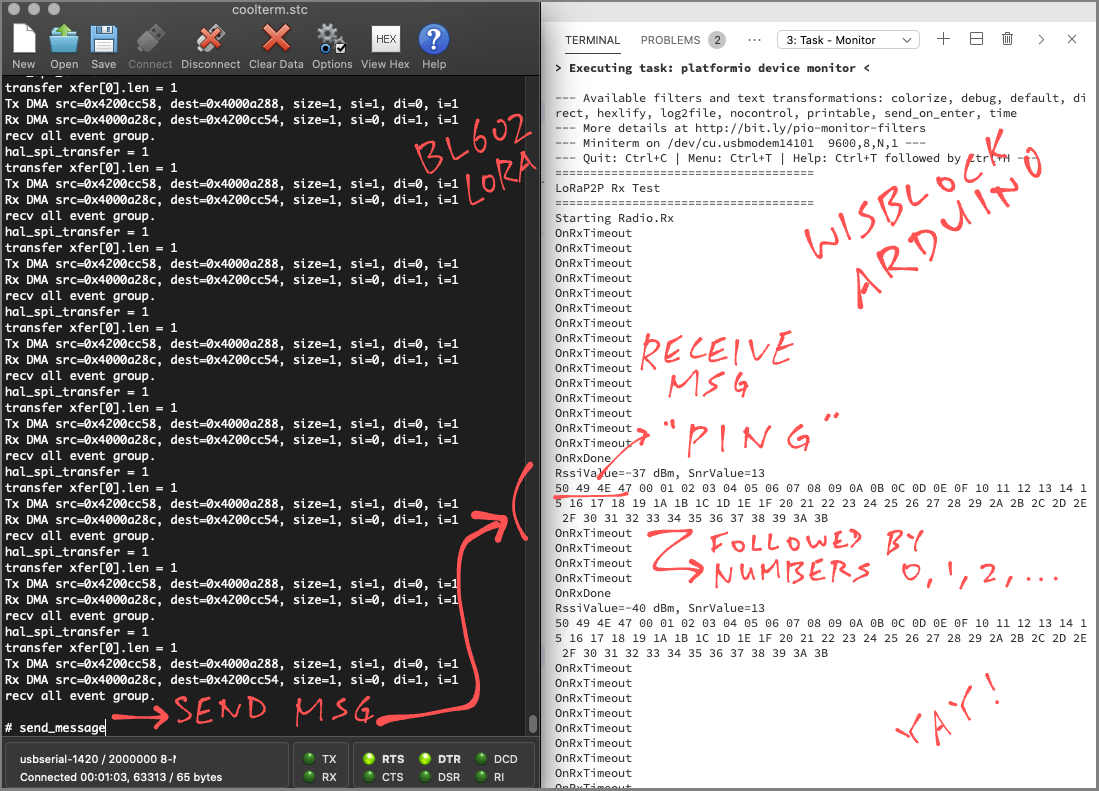
PineCone BL602 (left) sending LoRa packets to WisBlock (right)
Let’s run the LoRa Firmware for WisBlock and receive some LoRa Packets!
Follow the instructions in this excellent article to install VSCode and PlatformIO…
Remember to install the LoRa Library SX126x-Arduino according to the steps above.
(We may skip the LoRaWAN OTAA Example)
Find out which LoRa Frequency we should use for your region…
We’ll set the LoRa Frequency in a while.
Enter this at the command line…
## Download the wisblock-lora-receiver source code
git clone --recursive https://github.com/lupyuen/wisblock-lora-receiver
In VSCode, click File → Open Folder
Select the folder that we have just downloaded: wisblock-lora-receiver
Edit the file src/main.cpp
Look for this code…
// Define LoRa parameters.
// TODO: Change RF_FREQUENCY for your region
#define RF_FREQUENCY 923000000  // Hz
Change 923 to the LoRa Frequency for your region: 434, 780, 868, 915 or 923
Modify the LoRa Parameters in src/main.cpp so that they match those in the LoRa Transmitter (PineCone BL602)
Build the LoRa Firmware by clicking the Build icon at the lower left…
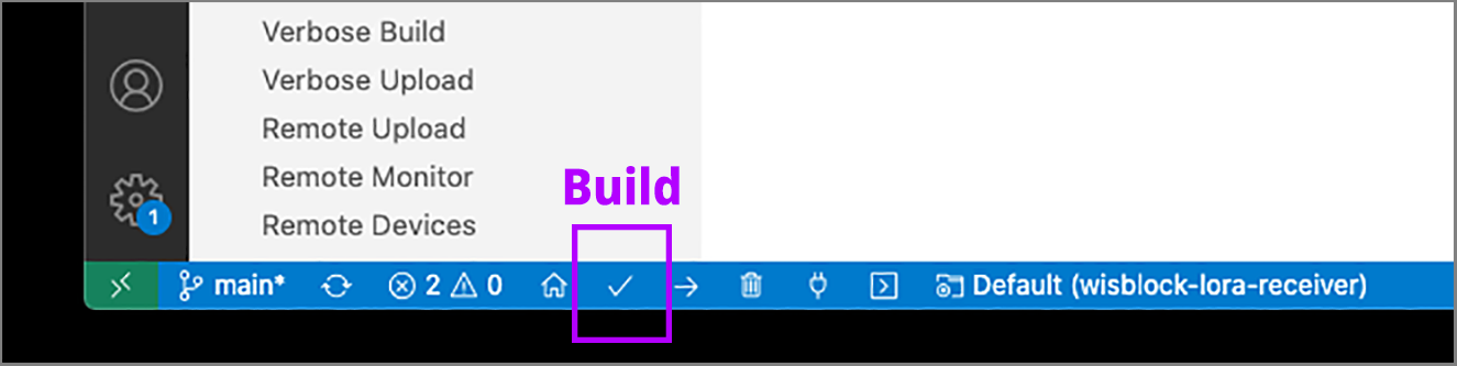
We should see this…
Processing wiscore_rak4631 (platform: nordicnrf52; board: wiscore_rak4631; framework: arduino)
...
Building in release mode
Checking size .pio/build/wiscore_rak4631/firmware.elf
Advanced Memory Usage is available via "PlatformIO Home > Project Inspect"
RAM:   [          ]   3.1% (used 7668 bytes from 248832 bytes)
Flash: [=         ]   7.3% (used 59800 bytes from 815104 bytes)
=========================== [SUCCESS] Took 4.49 seconds ===========================Connect WisBlock to our computer’s USB port
Flash the LoRa Firmware to WisBlock by clicking the Upload icon…
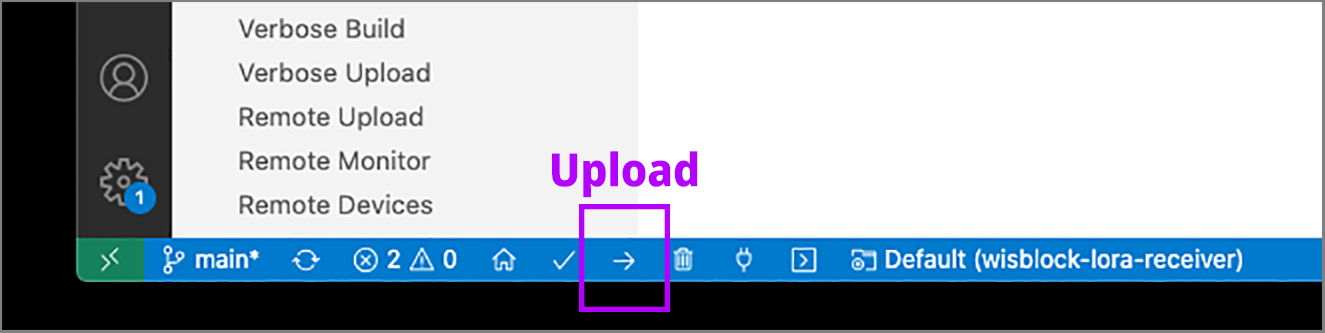
We should see this…
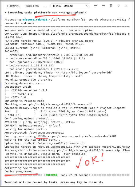
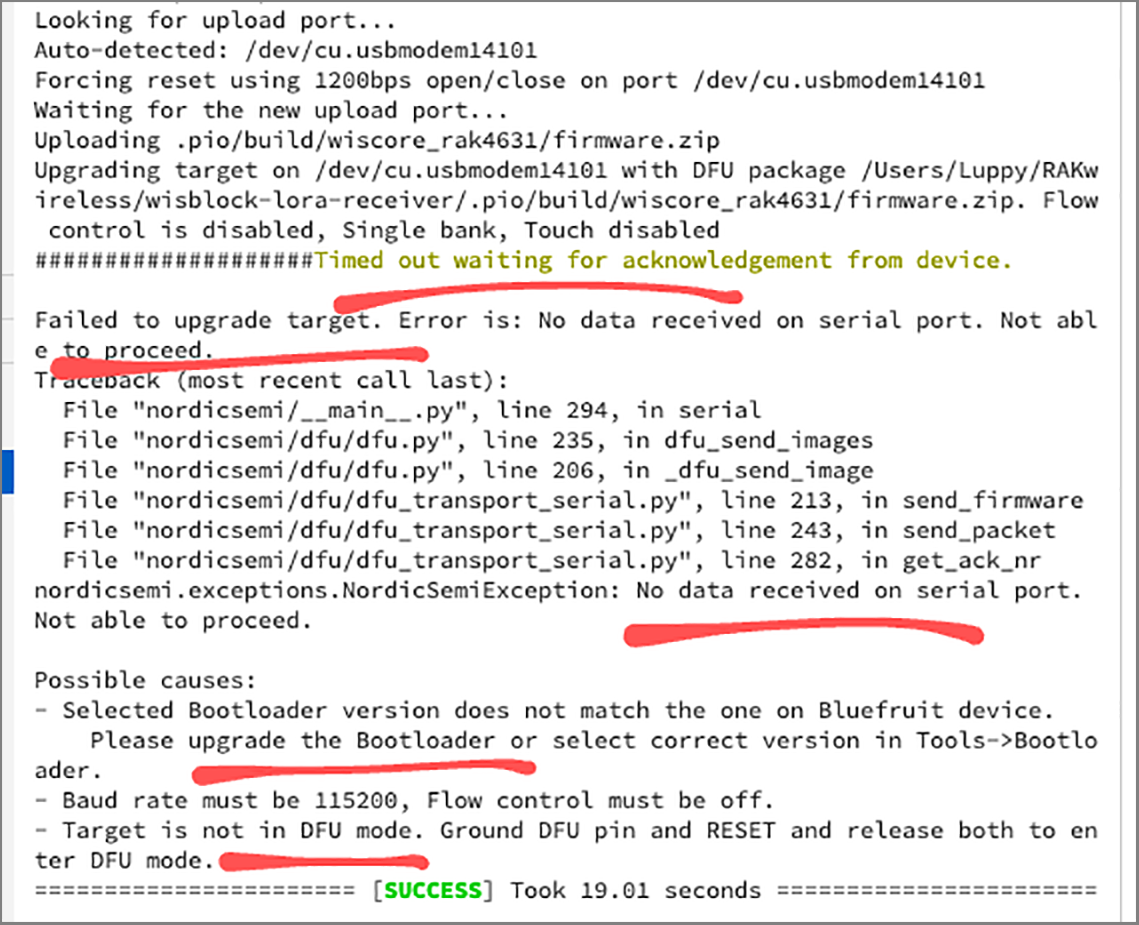
If we see the message…
Timed out waiting for acknowledgement from deviceThen disconnect WisBlock from the USB port, reconnect and flash again.
Run the LoRa Firmware by clicking the Monitor icon…
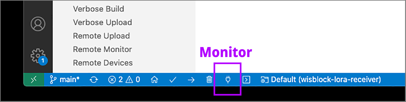
We should see this…
> Executing task: platformio device monitor <
--- Miniterm on /dev/cu.usbmodem14201  9600,8,N,1 ---
--- Quit: Ctrl+C | Menu: Ctrl+T | Help: Ctrl+T followed by Ctrl+H ---
Starting Radio.Rx
Power on our LoRa Transmitter (PineCone BL602) and start transmitting LoRa Packets.
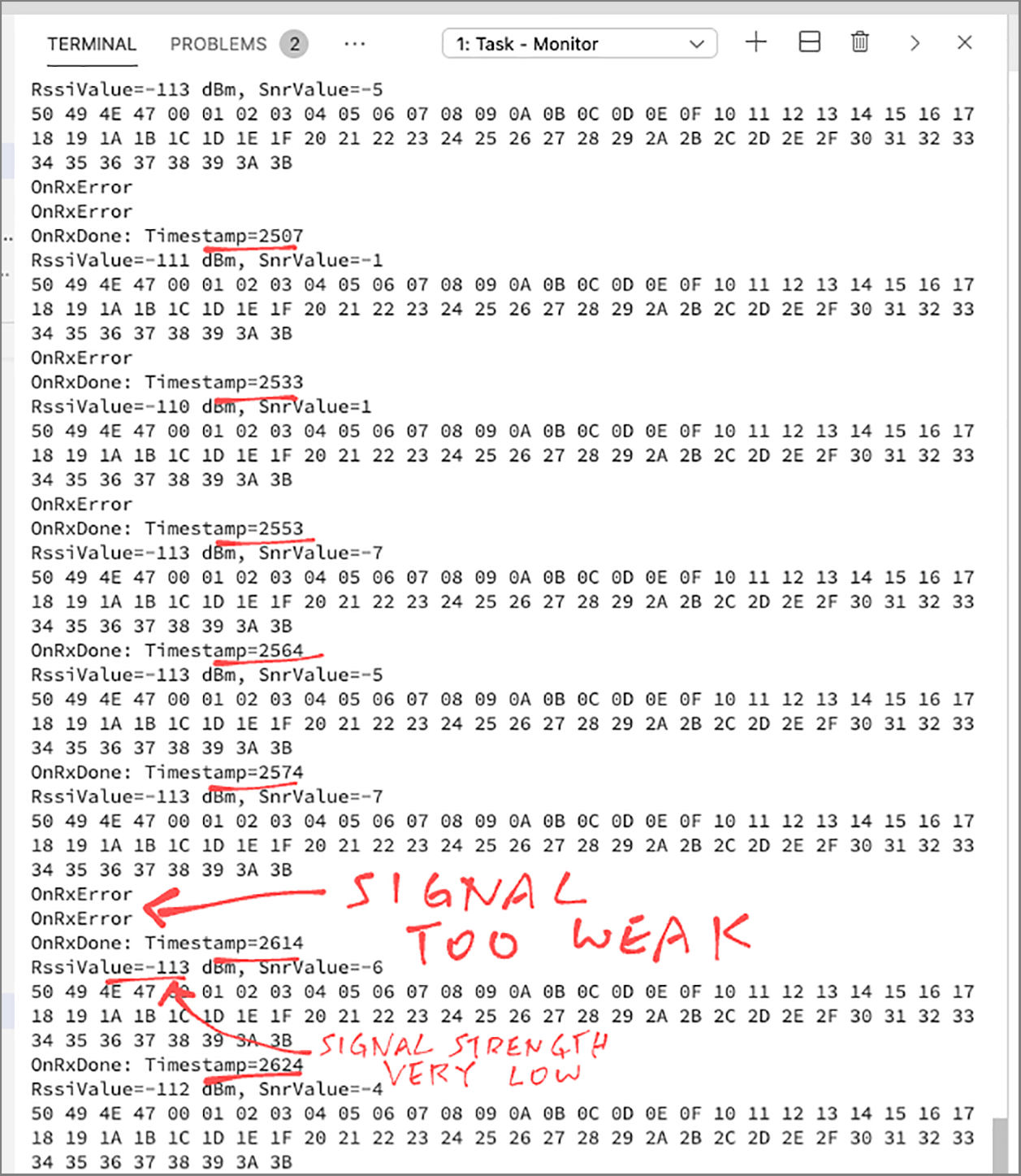
In the WisBlock Log we will see the LoRa Packet received…
OnRxDone:
Timestamp=23,
RssiValue=-48 dBm,
SnrValue=13,
Data=50 49 4E 47 00 01 02 03 04 05 06 07 08 09 0A 0B 0C 0D 0E 0F 10 11 12 13 14 15 16 17 18 19 1A 1B 1C 1D 1E 1F 20 21 22 23 24 25 26 27 28 29 2A 2B 2C 2D 2E 2F 30 31 32 33 34 35 36 37 38 39 3A 3B
Timestamp is the Timestamp in Seconds (which we’ll use for analysis in a while)
(We don’t have a real time clock so that’s the best timestamp we can get)
RssiValue is the Signal Strength of the received LoRa Packet (in dBm, decibel-milliwatts).
This number roughly varies from -50 (very strong signal) to -110 (very weak signal).
(Why is the number negative? Because it’s an exponent. See this)
SnrValue is the Signal To Noise Ratio.
This number roughly varies from -9 (very noisy signal) to 13 (very clear signal).
As we move the LoRa Transmitter (PineCone BL602) around, the Signal Strength and Signal To Noise Ratio will change…
OnRxDone:
Timestamp=196,
RssiValue=-63 dBm,
SnrValue=13,
Data=50 49 4E 47 00 01 02 03 04 05 06 07 08 09 0A 0B 0C 0D 0E 0F 10 11 12 13 14 15 16 17 18 19 1A 1B 1C 1D 1E 1F 20 21 22 23 24 25 26 27 28 29 2A 2B 2C 2D 2E 2F 30 31 32 33 34 35 36 37 38 39 3A 3B
When we move the LoRa Transmitter too far from the WisBlock Receiver, we will see this…
OnRxError: Timestamp=619This means that our WisBlock Receiver couldn’t receive the LoRa Packet because the signal was too weak.
Now that we understand LoRa Packets and their Signal Strength, let’s measure the LoRa Network Coverage!
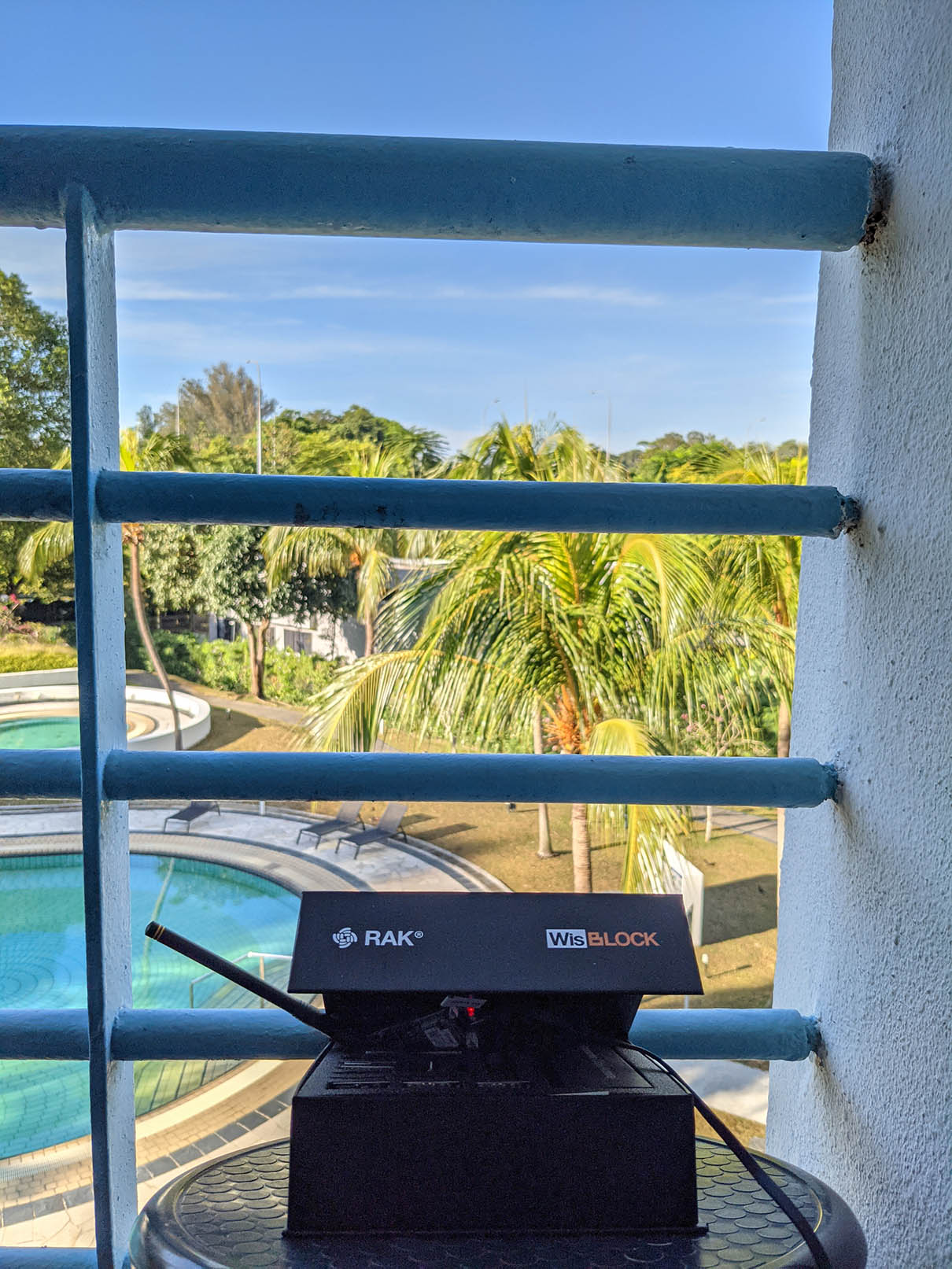
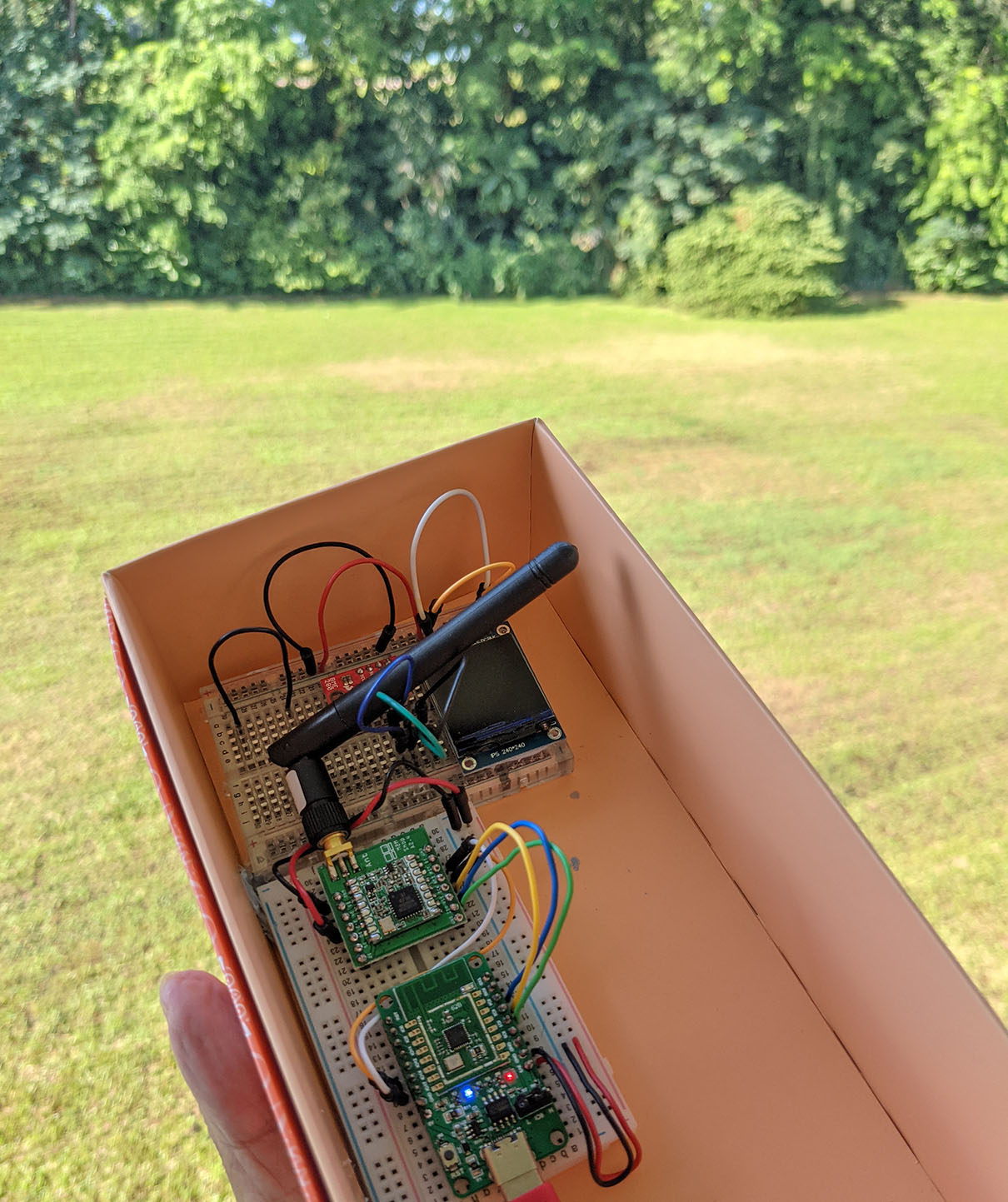
WisBlock LoRa Receiver right by the coconut trees
Here comes the #1 Question when deciding where to install our LoRa Sensor and LoRa Receiver…
What’s the Maximum Distance between the LoRa Transmitter and LoRa Receiver? 100 metres? 200 metres? Or more?!
LoRa was designed to send packets over great distances with little power. Let’s find out how far!
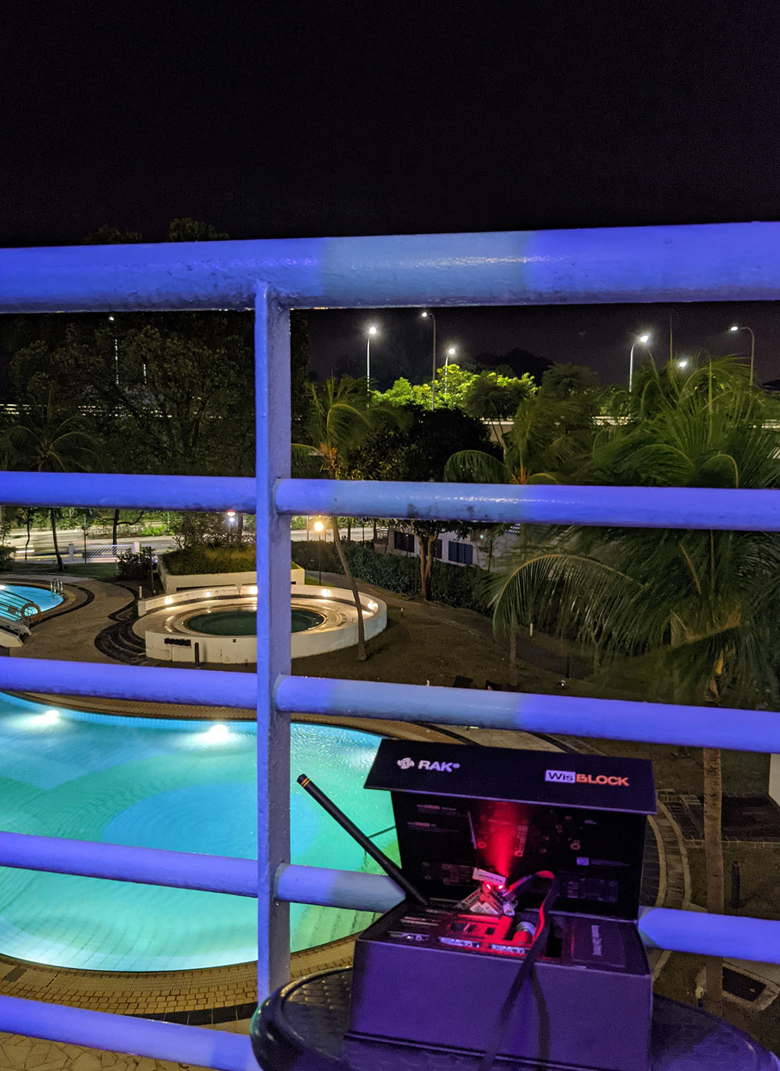
We’ll put our WisBlock LoRa Receiver on the balcony, right by the coconut trees. (See pic above)
(It’s OK to run WisBlock temporarily inside the padded WisBlock Connected Box, antenna sticking out and upwards… Just make sure the metal parts of the LoRa Antenna and the Bluetooth Antenna don’t touch any metal parts on WisBlock)
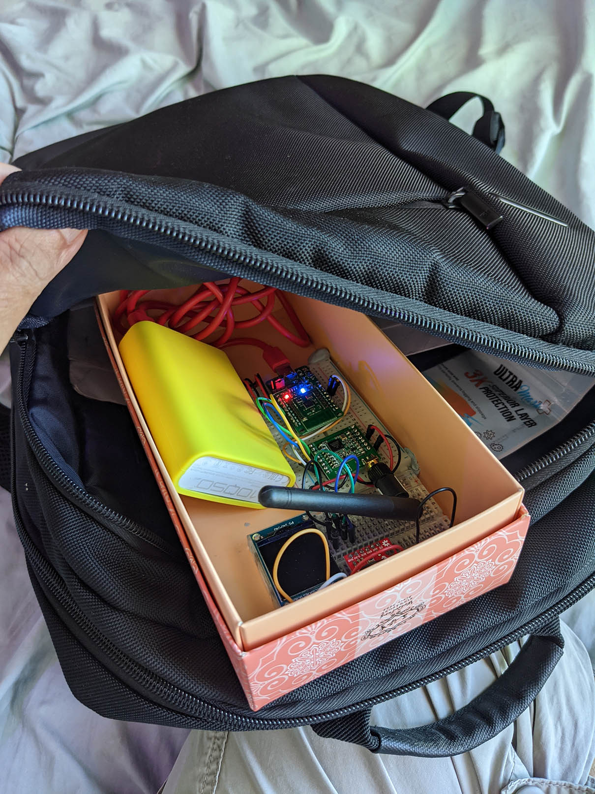
Prepare the LoRa Transmitter Kit. We’ll pack the following…
PineCone BL602 RISC-V Board, running the LoRa Ping Firmware (See the appendix)
LoRa Transceiver (Semtech SX1276 or Hope RF96)
Battery (Portable Charger)
Permeable Paper Box (So that LoRa Packets will penetrate the box easily)
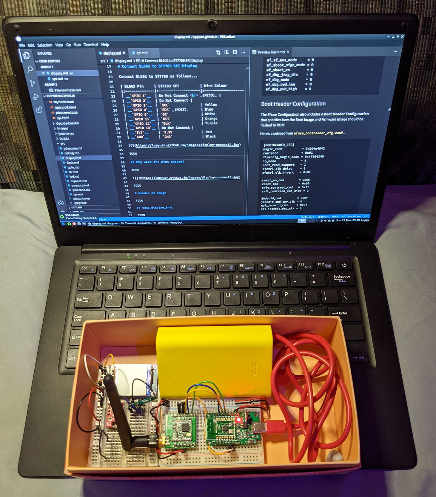
Pinebook Pro (In case we need to patch the PineCone Firmware)
Pack the LoRa Transmitter Kit into a backpack, antenna pointing up
Go hiking with the backpack!
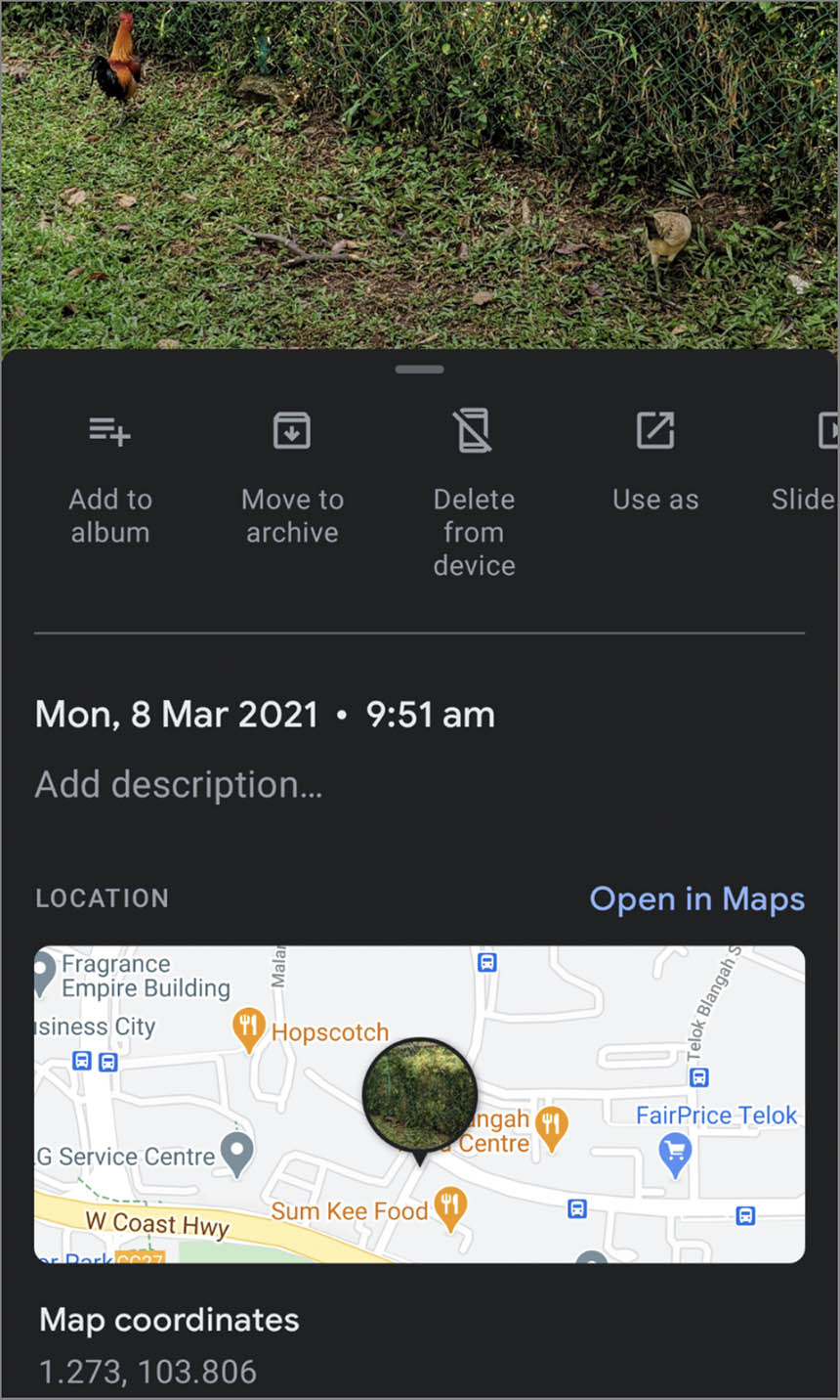
We’ll do it like Pokemon Snap… Everywhere we go, we snap a photo on our phone.
Like this Grassy Field…
This photo is Geocoded and Timestamped by our phone.
Later we shall use this photo to tell us where we were located at a specific time.
Keep snapping more photos as we walk. Like these Geocoded, Timestamped Chickens…
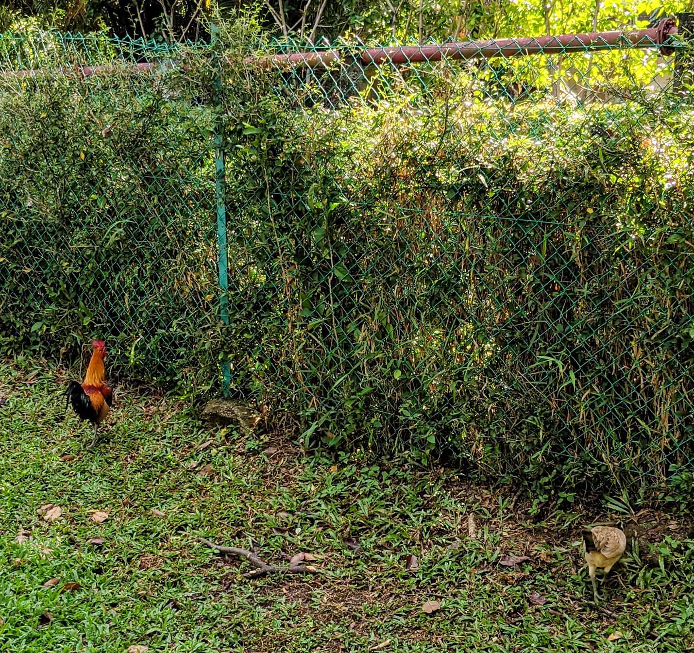
At the end of our hike, we’ll have a collection of Geocoded Timestamped Photos.
In the next section we’ll match the photos with the log of LoRa Packets received by WisBlock.
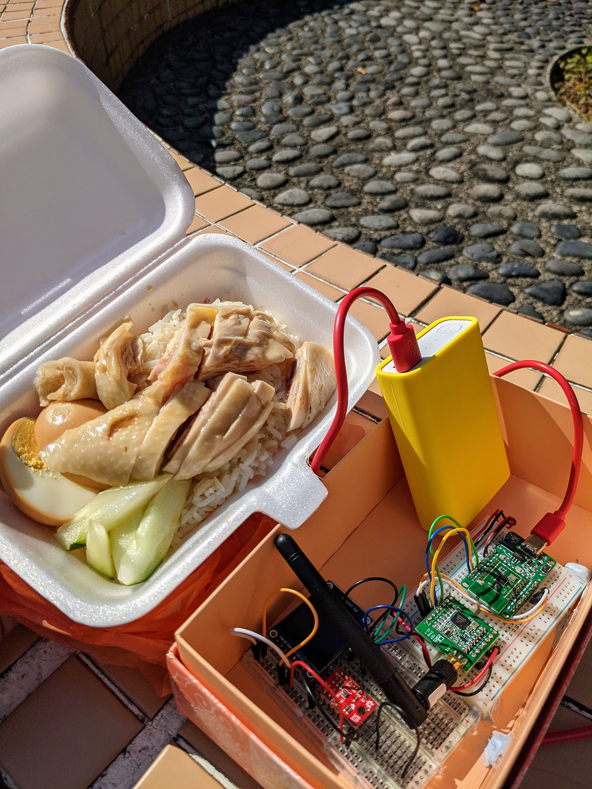
Geocoded, Timestamped Chicken Rice (no relation with the earlier chickens)
Back to our #1 Question…
What’s the Maximum Distance between the LoRa Transmitter and LoRa Receiver? 100 metres? 200 metres? Or more?!
To answer that, we have two helpful things…
A bunch of Geocoded, Timestamped Photos that we have collected during our LoRa Field Test
A log of LoRa Packets received by WisBlock…
See the log of received LoRa Packets
Here’s what we’ll do…
We copy and paste the log of received LoRa Packets into a spreadsheet.
Split the data neatly into columns.
Based on the Timestamp (in seconds), we compute the Actual Time Of Day.
Our spreadsheet should look like this…
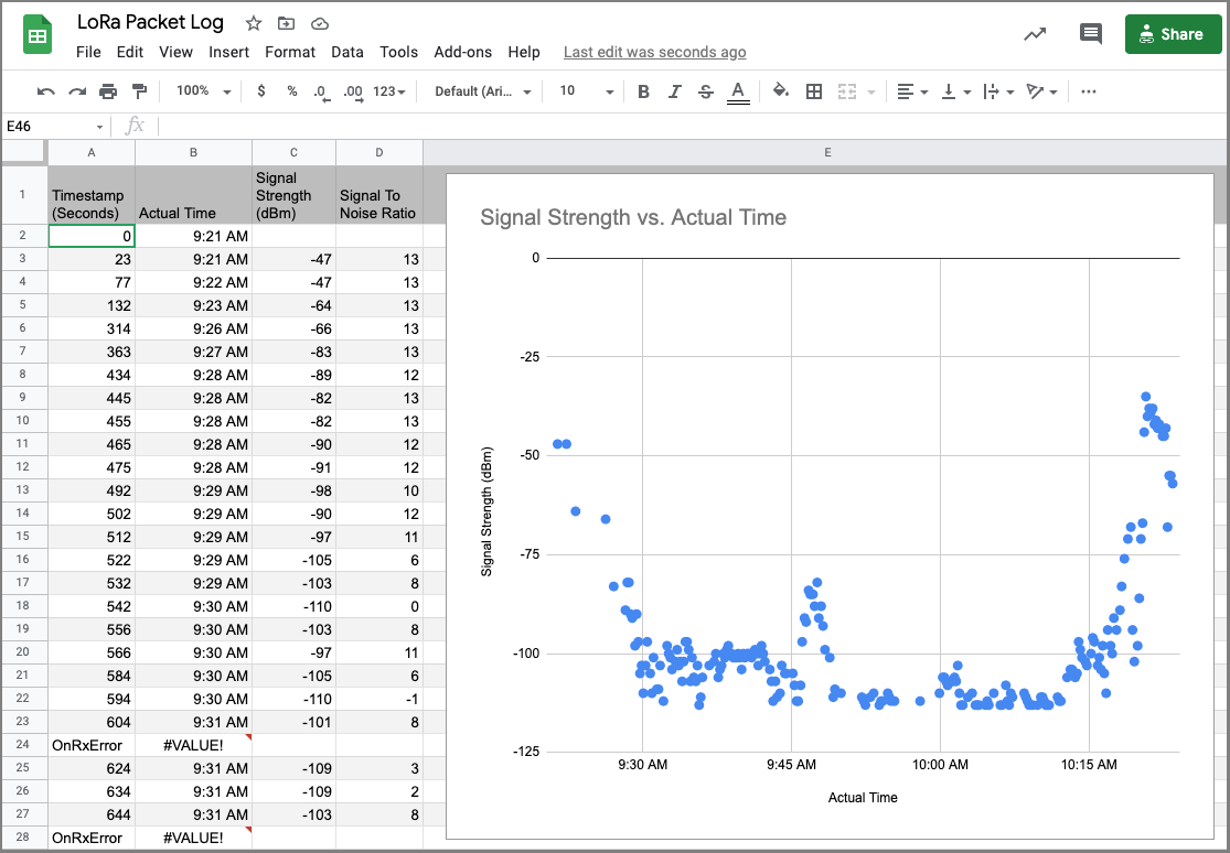
Plot a chart of Signal Strength vs Actual Time (See pic above)
This shows us the Signal Strength of the LoRa Packets received by WisBlock as we walked about.
Look for the dips and valleys in the chart.
These are the places with poor LoRa Coverage.
When we see missing dots in the chart,these are the places with zero LoRa Coverage.
(Don’t place our LoRa Sensor here!)
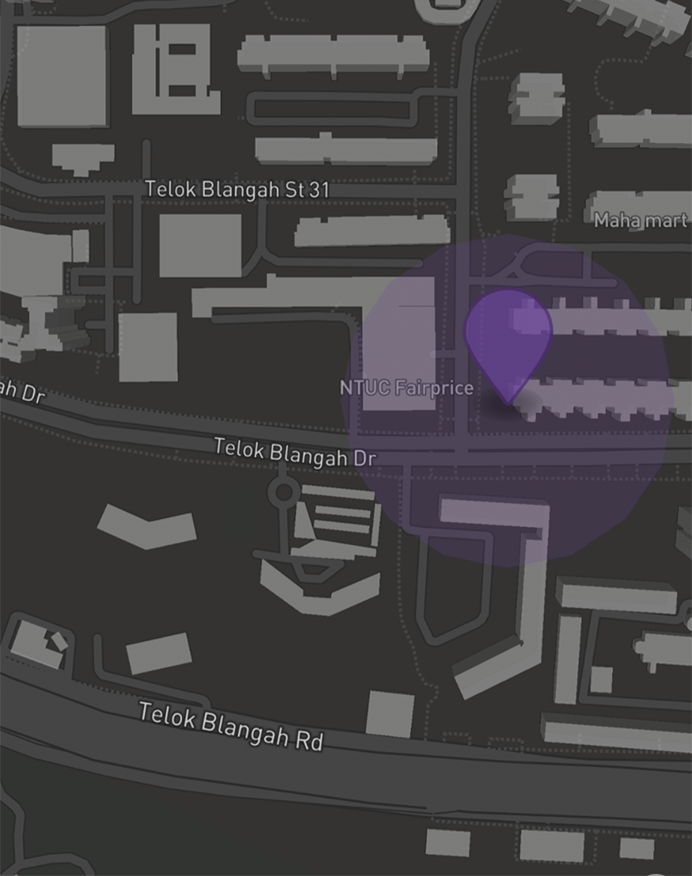
To find these places with poor LoRa Coverage, match the Actual Time against the photos that we have collected…
Each photo is Geocoded, so we can identify the places. Voila!
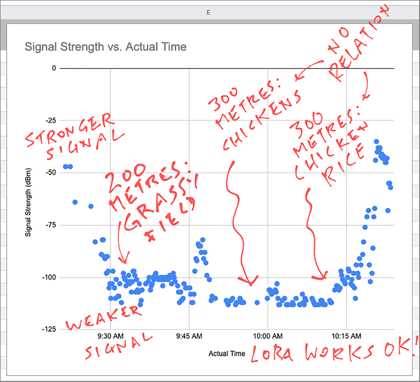
For this test, we were able to receive LoRa Packets up to 300 metres away.
Not bad for this dense, blocky neighborhood!
How is this possible when there’s No Line Of Sight between the LoRa Transmitter and the LoRa Receiver?
LoRa Packets can get reflected on building surfaces… And the reflected packets will be received OK.
(Assuming little signal distortion)
LoRa Packets can penetrate light vegetation.
(Like our paper box)
Exercise For The Reader…
How would you conduct this LoRa Field Test and analyse the LoRa Network Coverage more efficiently?
WisBlock receiving LoRa packets in the night
In the next article we shall head back to PineCone BL602 and finish Level 1 of our LoRa Stack…
Today BL602 can transmit LoRa Packets to WisBlock
Tomorrow BL602 shall receive LoRa Packets transmitted by WisBlock
And then we can progress to LoRa Levels 2 and 3: LoRaWAN and The Things Network.
Read the next article here…
We have come a loooong way since I first experimented with LoRa in 2016…
Cheaper Transceivers: Shipped overnight from Thailand!
Mature Networks: LoRaWAN, The Things Network
Better Gateways: RAKwireless WisGate
Awesome Tools: RAKwireless WisBlock, Airspy SDR, RF Explorer
Now is the right time to build LoRa gadgets. Stay tuned for more LoRa Adventures!
Got a question, comment or suggestion? Create an Issue or submit a Pull Request here…
lupyuen.github.io/src/wisblock.md
In the previous article we’ve created a LoRa Transmitter with PineCone BL602…
For the LoRa Field Test we installed the BL602 LoRa Ping Firmware: sdk_app_loraping
This is a modified version of sdk_app_lora that does the following…
At startup, we initialise the LoRa Transceiver
Then we transmit a 64-byte PING LoRa Message every 10 seconds
We flash the Blue LED on PineCone every 10 seconds
The changes are made in the function cli_init in demo.c
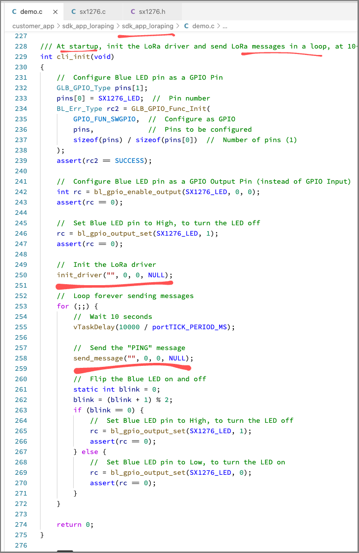
Modified cli_init function
Remember to check that the BL602 LoRa Parameters in LoRa Ping match those in the WisBlock Receiver.
From demo.c
BL602 LoRa Parameters
Here’s how it looks when BL602 LoRa Ping sends LoRa Packets to WisBlock…
PineCone BL602 (left) sending LoRa packets to WisBlock (right)
There seems to be an intermittent problem with my LoRa Transmitter (hardware or firmware?)… WisBlock receives the first LoRa Packet transmitted but doesn’t receive subsequent packets.
My workaround for now: As I walk, I disconnect and reconnect the USB power to my LoRa Transmitter (every 20 seconds).
When we’re out doing the LoRa Field Test, how far shall we walk?
Is there some way to watch the log of packets received by WisBlock… As we walk?
Here’s a solution: We stream the WisBlock Arduino Log live to YouTube!
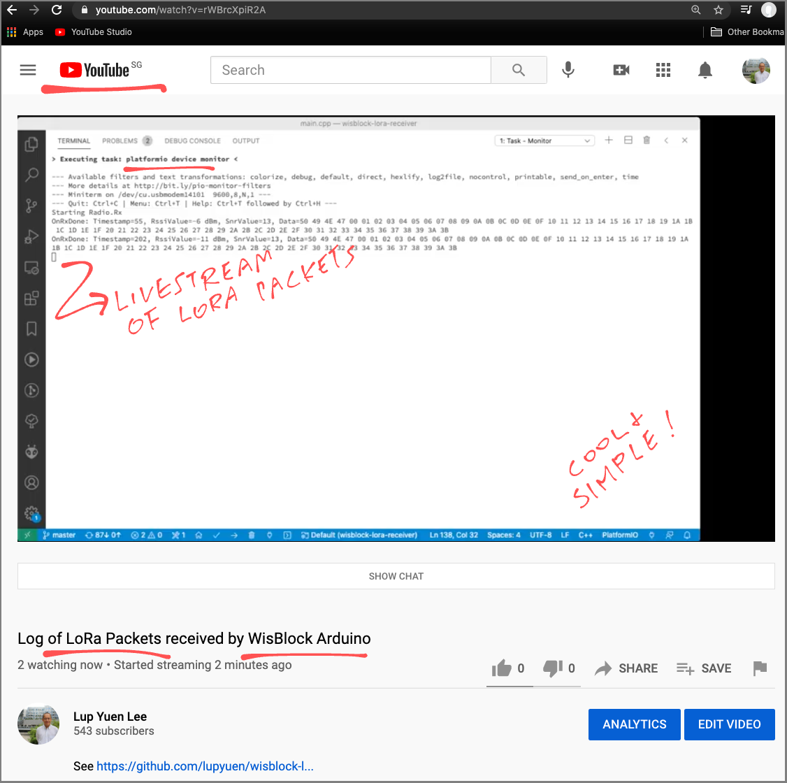
Livestream of WisBlock Arduino Log on YouTube
Watch the recoded video on YouTube
We do this by running OBS Studio on our computer.
OBS Studio streams our desktop to YouTube as a live video stream, so that we may watch the WisBlock Arduino Log on the go.
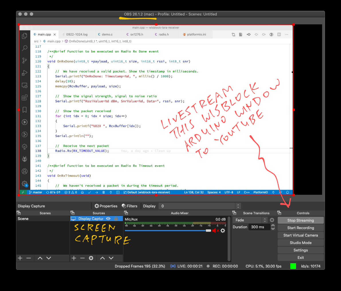
OBS Studio streaming WisBlock Arduino Log to YouTube