📝 11 May 2020
[ UPDATE: Check out the followup article here ]
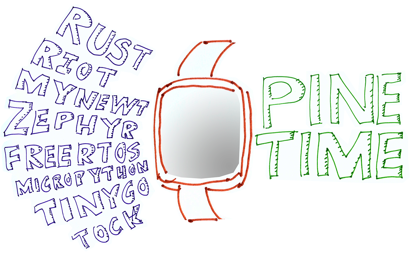
Thanks to the FOSS Community, PineTime Smart Watch has an incredible variety of FOSS operating systems in the works: FreeRTOS, MicroPython, Mynewt, RIOT, Rust RTFM (another), TinyGo, Tock, Zephyr (another, yet another), ...
But these embedded platforms are accessible only by brave PineTime Owners who dare to pry open their watches very carefully... And connect a Raspberry Pi (or ST-Link) to the tiny delicate 4-pin SWD port recessed deep inside... Just to flash the PineTime firmware.
What if we could flash any firmware to PineTime from our mobile phone... Without opening the watch?
Yes we can! Just download the firmware file into our phone and push it wirelessly to our watch, like this...
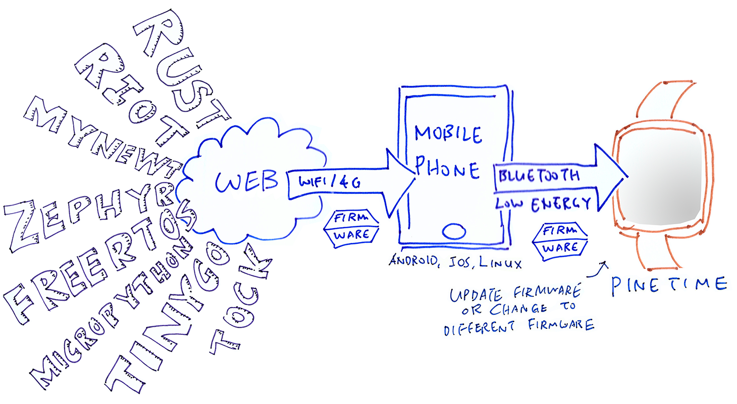
Firmware Update over Bluetooth Low Energy for PineTime Smart Watch
What's the magic behind this? It's the Simple Management Protocol (SMP)
By transmitting a bunch of SMP messages over Bluetooth Low Energy (LE), it's possible to send a file to PineTime and update its firmware. (Assuming that our PineTime supports SMP)
What mobile app would we use for flashing PineTime over Bluetooth LE?
The Nordic nRF Connect mobile app for iOS and Android is all that we need for flashing PineTime. Here's how it looks when the app is connected to a PineTime that supports SMP...
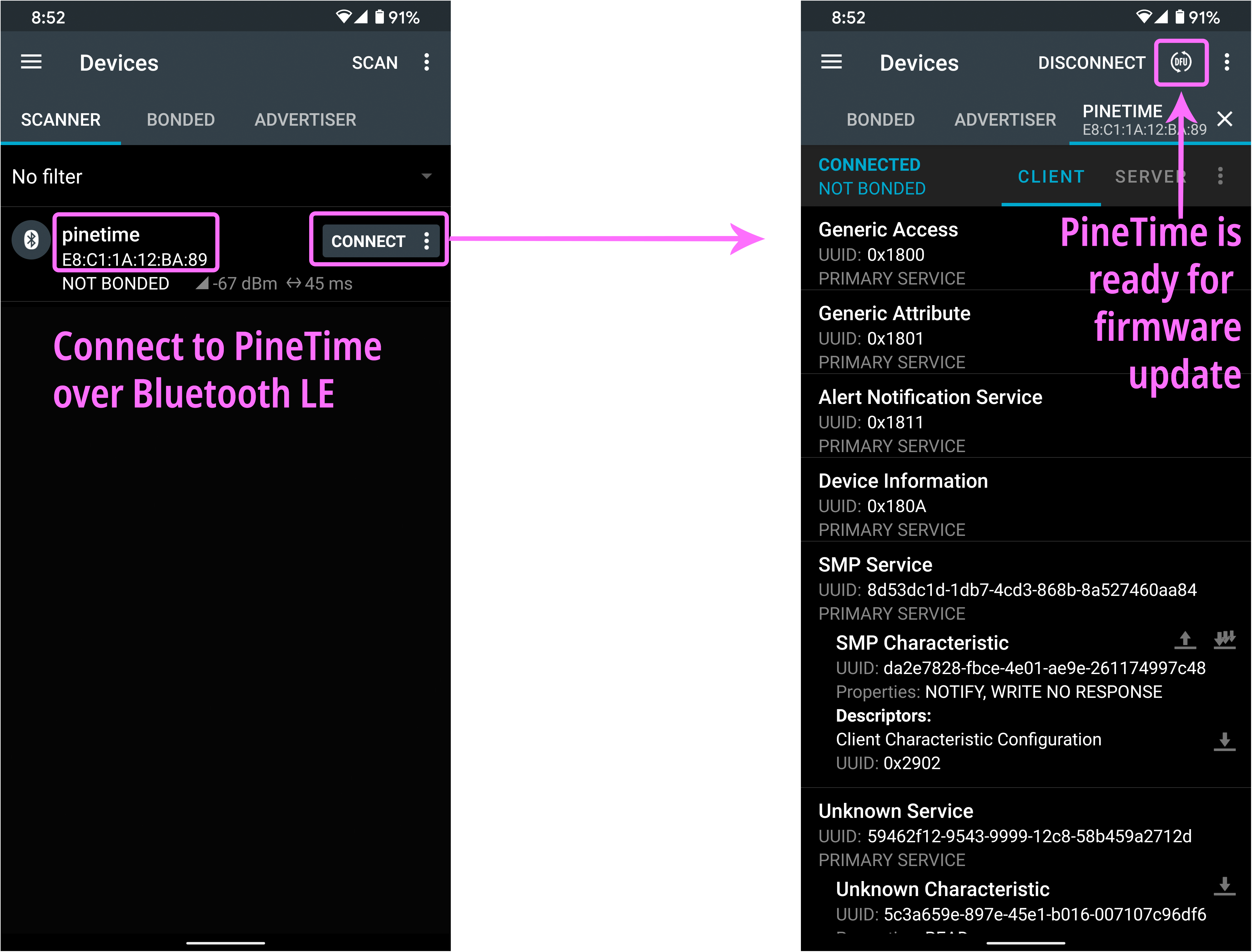
nRF Connect mobile app connected to PineTime for Firmware Update
See the circular DFU icon at the top right? That stands for Direct Firmware Upgrade.
Tapping the DFU icon will let us select a downloaded firmware file for flashing our watch. It's really that easy!
What about PinePhone? Raspberry Pi?
PinePhone, Raspberry Pi and other Linux devices may use the open-source Newt Manager tool. (I have tested Newt Manager on Raspberry Pi with PineTime)
It runs on a command line, but it should be easy to wrap up in a graphical user interface.
What needs to be done on PineTime?
If you're developing firmware for PineTime: Thanks for the great job! I strongly urge you to implement the SMP protocol in your firmware... It will make PineTime Owners a lot happier when updating their watch firmware!
And we'll give PineTime Owners an easy way to try out all the awesome platforms that the PineTime FOSS Community has to offer!
We would like Pine64 to ship PineTime with a FOSS firmware (created by the PineTime Community) that implements the SMP protocol. So PineTime owners can just unbox their watch and start flashing right away from their phones.
In this article I'll walk you through the steps of implementing the SMP protocol in your PineTime firmware. I'll show you my implementation for Mynewt OS, which you may use for reference.
The open-source Simple Management Protocol (SMP) was originally created for flashing firmware on devices running Mynewt and Zephyr operating systems. SMP is based on the Bluetooth LE Generic Attribute (GATT) Profile.
GATT defines the standard way for a Bluetooth LE Client (like our mobile phone) to access a Bluetooth LE Service (like the firmware update service on PineTime). More about GATT
Here's how the SMP protocol works...
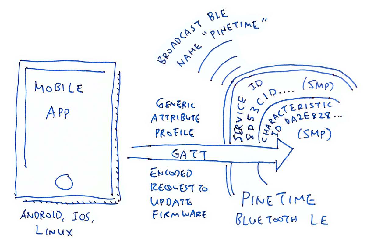
SMP Firmware Update over Bluetooth LE
PineTime broadcasts its name pinetime over Bluetooth LE to allow mobile phones to discover the smart watch
Mobile App connects to PineTime via the advertised name pinetime
Mobile App queries PineTime for a GATT Service that has ID 8D53DC1D-1DB7-4CD3-868B-8A527460AA84. This is the GATT Service ID for SMP.
Mobile App then queries PineTime for the GATT Characteristic ID DA2E7828-FBCE-4E01-AE9E-261174997C48. This is the GATT Characteristic ID for SMP.
Mobile App uses the GATT Characteristic ID for SMP to transmit an encoded request to update PineTime's firmware. In GATT lingo, we call this sending a "Write Request" to the GATT Characteristic for SMP.
PineTime performs the firmware update using the firmware file that was embedded in the request
This flow becomes clearer when we look at the nRF Connect mobile app connected to PineTime. Observe how we connect to PineTime by the device name pinetime, also note the SMP Service and SMP Characteristic that appear under PineTime...
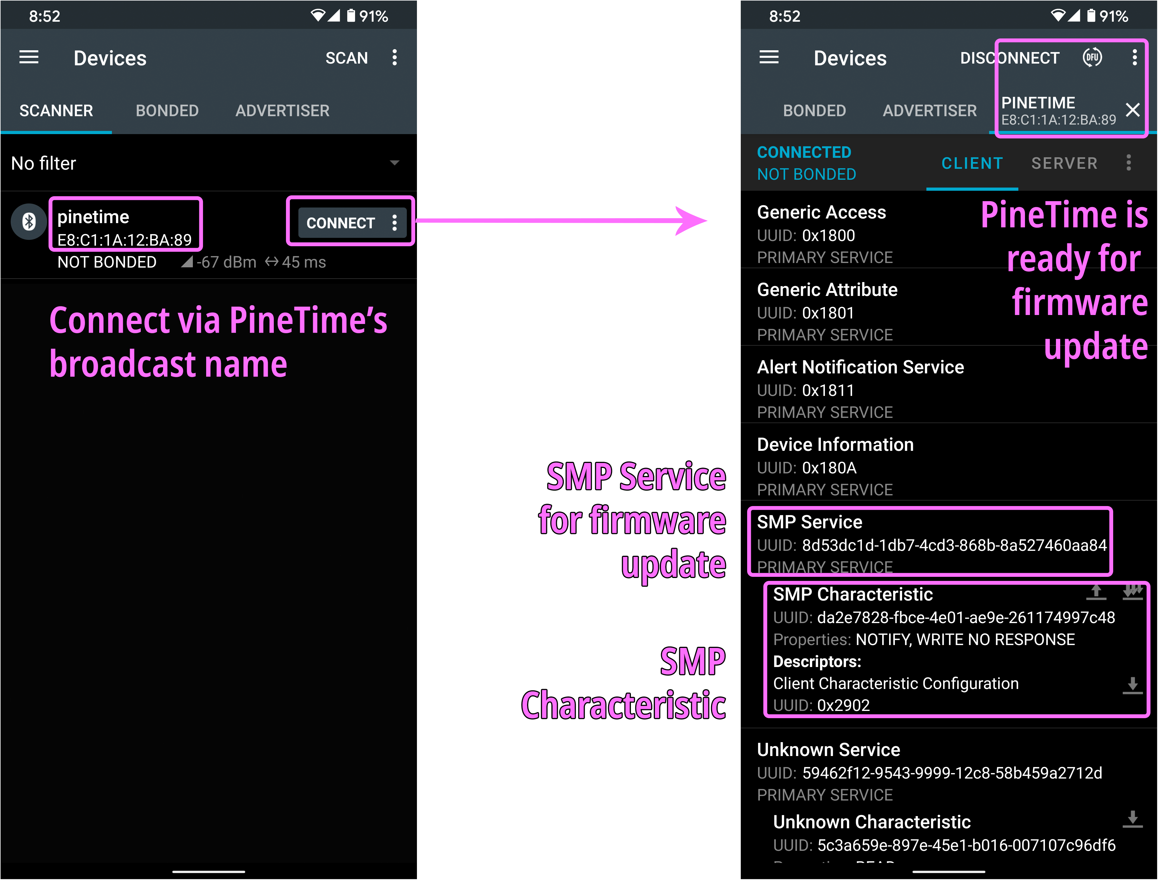
nRF Connect mobile app connected to PineTime's SMP Service
The circular DFU icon at top right (Direct Firmware Upgrade) appears when the mobile app detects the presence of the SMP Service and Characteristic. Tapping the DFU icon will transmit a firmware update request to PineTime.
How shall we implement the SMP protocol in PineTime firmware?
Fortunately there's an open-source library that implements the SMP protocol: the MCU Manager Library. More about this in a while.
For reference, the generic SMP protocol is documented here. The SMP protocol based on Bluetooth LE is documented here.
PineTime Smart Watch will be worn by people of all ages (maybe pets too)... Thus we shall plan for failure!
What happens if the firmware gets corrupted or truncated while transmitting the firmware update over Bluetooth LE? Will PineTime get bricked?
We won't overwrite the existing firmware as we receive the new firmware. We'll stage the new firmware in a separate area in PineTime's Flash ROM.
We'll overwrite the existing firmware only when we're absolutely sure that the new firmware has passed our integrity checks.
What happens if there's a bug in the new firmware that causes PineTime to crash during startup?
We'll roll back the firmware to the previous version. Here's how it works...
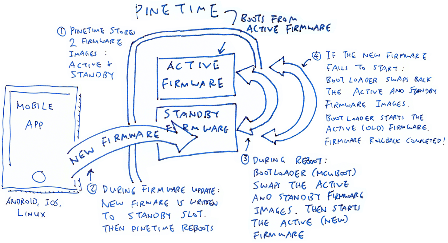
Firmware Update with Rollback on PineTime
PineTime stores two firmware images in Flash ROM: Active and Standby. PineTime boots from the Active Firmware Image. It activates the SMP service for firmware update over Bluetooth LE.
During firmware update, PineTime writes the received firmware image into the Standby Firmware slot. PineTime checks that the firmware image has been received correctly, and reboots itself.
On reboot, the bootloader (MCUBoot) swaps the Active and Standby Firmware images. The bootloader starts the Active Firmware Image (containing the new firmware)
If the new firmware doesn't start properly, at the next reboot the bootloader swaps back the Active and Standby Firmware images. The bootloader starts the Active Firmware Image (now containing the old firmware)
PineTime should start correctly with the old firmware with SMP service operational. We may perform the firmware update again when the new firmware is fixed.
Thankfully most of this firmware update and rollback logic is built into the MCU Manager Library. For the swapping of firmware we'll use another open-source component: MCUBoot Bootloader. More about MCUBoot in a while.
To support firmware update (with rollback) via Bluetooth LE, PineTime Firmware Developers would have to adopt a common layout for storing flash images in Flash ROM.
Here's the proposed Flash ROM Layout that supports Active and Standby Firmware Images for firmware update and rollback...
| Flash ROM Area | Address | Size |
|---|---|---|
| Bootloader (MCUBoot) | 0x0000 0000 | 28 KB |
| Reboot Log | 0x0000 7000 | 4 KB |
| Active Firmware Image | 0x0000 8000 | 464 KB |
| Scratch Area | 0x0007 C000 | 4 KB |
TODO: 0x7f00 to 0x7fff is reserved for the relocated Vector Table. Active Firmware Image should be extended by 12 KB. Scratch Area should be moved down by 12 KB
And the layout for PineTime's SPI Flash...
| SPI Flash Area | Address | Size |
|---|---|---|
| Bootloader Assets | 0x0000 0000 | 256 KB |
| Standby Firmware Image | 0x0004 0000 | 464 KB |
| User File System | 0x000B 4000 | 3,376 KB |
TODO: Standby Firmware Image should be extended by 12 KB. User File System should be moved down by 12 KB
Proposed Flash ROM Layout for PineTime. Derived from this Flash ROM layout for nRF52832.
Bootloader: Located at the start of PineTime's Flash ROM, the open-source MCUBoot Bootloader is the first thing that PineTime runs upon booting.
For firmware update and rollback, the Bootloader swaps the Active and Standby Firmware Images. Then it jumps to the Active Firmware code.
Reboot Log: This is a log of debugging messages generated by the firmware upon starting. Useful for debugging startup failures.
Active Firmware Image: Contains PineTime firmware code that will be executed. The image starts with a Firmware Image Header (0x20 bytes) followed by the Arm Cortex-M4 Interrupt Vector Table (0xD8 bytes).
Hence the executable firmware code begins at address 0x0000 80F8. PineTime Firmware Developers should assume that their firmware code will be located at this address.
Standby Firmware Image: Staging area for receiving the new firmware over Bluetooth LE. During firmware update, the Bootloader swaps the Active and Standby Firmware Images, so that the new firmware becomes active.
If the new firmware fails to start, the Bootloader swaps the old firmware back so that the old firmware becomes active.
Scratch Area: Temporary storage used by the Bootloader for swapping the Active and Standby Firmware Images.
User File System: PineTime Firmware Developers may store the user's settings here. The contents of this flash area are preserved during firmware updates.
Now we'll learn how the MCU Manager Library manages the Active and Standby Firmware Images to perform firmware updates.
More details on the Flash ROM Layout
Let's look at the MCU Manager Library (coded in C) and how it handles firmware updates...
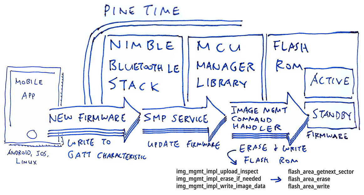
Firmware Update with MCU Manager Library
Mobile App transmits the new firmware to PineTime over Bluetooth LE in mutiple chunks. Mobile App writes each chunk of firmware as an Image Upload Request to the SMP Characteristic on PineTime's GATT interface.
The open-source NimBLE Bluetooth LE networking stack interprets each Image Upload Request request and calls the Command Handler for Image Management, part of the MCU Manager Library. More about NimBLE in a while.
Image Management Command Handler (in MCU Manager Library) inspects the Image Upload Request, by calling img_mgmt_impl_upload_inspect
Image Management Command Handler erases the Standby Firmware Image in PineTime's Flash ROM, by calling img_mgmt_impl_erase_if_needed
Then it writes the received firmware chunk into the Standby Firmware slot by calling img_mgmt_impl_write_image_data
PineTime Firmware Developers would need to implement these functions in C to inspect, erase and write firmware images in Flash ROM...
Inspect Upload: img_mgmt_impl_upload_inspect(&req, &action, &errstr)
Inspects the Image Upload Request in req (defined here) and returns 0 if valid:
off: Offset of this chunk. Starts at 0.
size: Total size of the firmware image
data_len: Size of this chunk
data_sha_len: Size of the SHA hash
upgrade: If true, the version number of the new firmware must be greater than the Active Firmware version in Flash ROM
The function also sets action (defined here) to specify how the Image Upload Request should be handled:
size: Total size of the firmware image
write_bytes: Number of image bytes to write to flash for the chunk
area_id: The flash area to write to
proceed: Whether to process the request; false if offset is wrong.
erase: Whether to erase the destination flash area.
Refer to the reference implementation here: mynewt_img_mgmt.c
Erase Image: img_mgmt_impl_erase_if_needed(offset, num_bytes)
Erase a sector in Flash ROM. Erasing the entire Flash ROM at one time can take significant time, causing Bluetooth disconnect or significant battery sag. That's why we will erase a sector immediately before writing it.
Refer to the reference implementation here: mynewt_img_mgmt.c
Write Image: img_mgmt_impl_write_image_data(offset, data, num_bytes, last)
Write the chunk of uploaded firmware to the Standby Firmware slot. We'll cover this function in the next section.
The usage of these functions may be found in img_mgmt.c
The complete list of C functions for Image Management to be implemented by PineTime Firmware Developers may be found here: img_mgmt_impl.h
Note that the Active Firmware is stored in Slot 0 and the Standby Firmware is stored in Slot 1 (or the Spare Slot).
To update PineTime's firmware over Bluetooth LE, the MCU Manager Library calls img_mgmt_impl_write_image_data to write each chunk of received firmware to PineTime's Flash ROM. PineTime Firmware Developers would have to implement img_mgmt_impl_write_image_data in C, so let's look inside the function...
int img_mgmt_impl_write_image_data(
    unsigned int offset,
    const void *data,
    unsigned int num_bytes,
    bool last);
img_mgmt_impl_write_image_data writes the chunk of firmware in data to the Standby Firmware Image (Slot 1), at the target offset indicated by offset.
num_bytes is the number of bytes in the chunk of firmware. last is true if this is the last chunk of firmware for the entire firmware update. The function returns 0 on success.
According to the reference implementation, the function does the following...
PineTime's Flash ROM is accessed as Flash ROM Sectors when writing and erasing the Flash ROM. PineTime's 512 KB Flash ROM is divided into 128 Sectors, with 4 KB per Sector.
For every Flash ROM Sector (4 KB each) that will be written:
Call flash_area_getnext_sector( fa->fa_id, §or_id, §or) to get the Flash ROM Sector ID (sector_id, from 0 to 127) and Flash ROM Sector Details (sector).
fa is the handle to the Standby Firmware ROM Area.
Then erase the Flash ROM Sector (set all bits to 1) by calling flash_area_erase( §or, 0, sector.fa_size)
Write the firmware data to the Standby Firmware Flash ROM by calling flash_area_write( fa, offset, data, num_bytes)
For details on the parameters of the flash_area_* functions, refer to the function declarations in flash_map.h
Why do we erase PineTime's Flash ROM before writing?
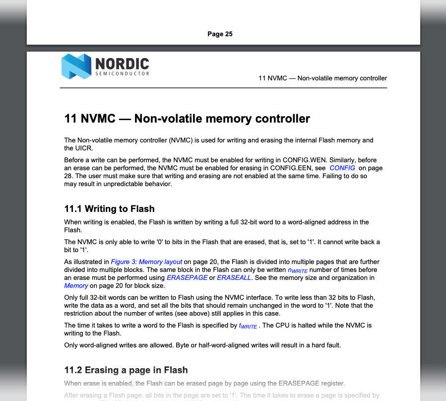
PineTime's Internal Flash Controller (nRF52832 NVMC) can only write 0 bits to Flash ROM. To write 1 bits, we erase the Flash ROM to set all bits to 1, then write the 0 bits.
That's why we call flash_area_erase before flash_area_write.
How shall we implement flash_area_erase to erase PineTime's Flash ROM?
According to the official documentation...
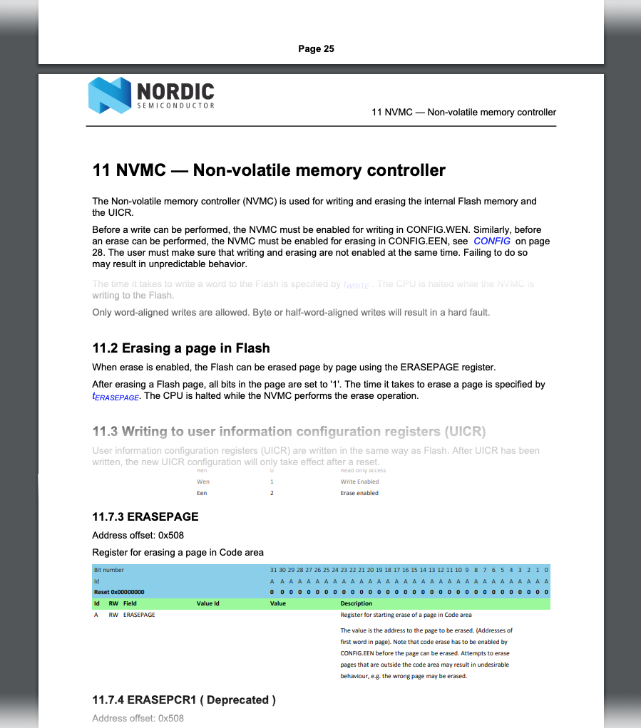
Erasing Flash ROM on nRF52832. From Nordic nRF52832 Product Specification
We should erase the Flash ROM like this...
Set the CONFIG Register to EEN (value 2) to enable erase
Set the ERASEPAGE Register to the address of the 4 KB Flash ROM Sector to be erased. (That's the address of the first word in the Flash ROM Sector)
Set the CONFIG Register to REN (value 0) to disable erase
For the reference implementation of flash_area_erase, check out nrf52k_flash_erase_sector in Mynewt's Flash Driver for nRF52.
How shall we implement flash_area_write to write to PineTime's Flash ROM?
Writing to Flash ROM on nRF52832. From Nordic nRF52832 Product Specification
We should write to the Flash ROM like this...
Set the CONFIG Register to WEN (value 1) to enable writing
Write the data (4 bytes at a time) to the target Flash ROM address
Set the CONFIG Register to REN (value 0) to disable writing
For the reference implementation of
flash_area_write, check out nrf52k_flash_write in Mynewt's Flash Driver for nRF52.
How shall we implement flash_area_getnext_sector to get the Flash ROM Sector?
The reference implementation of flash_area_getnext_sector may be found in flash_map.c.
The function returns the 4 KB Flash ROM Sector that corresponds to an address in the Standby Flash ROM Area, by walking through the list of Flash ROM Sectors.
NimBLE is an open-source networking stack for Bluetooth LE, coded in C. NimBLE talks directly to the Bluetooth hardware controller on PineTime's nRF52 microcontroller. NimBLE supports Nordic nRF51 and nRF52 microcontrollers
To support firmware updates over Bluetooth LE, PineTime Firmware Developers would have to include NimBLE in their firmware. NimBLE takes care of the firmware update process by interpreting GATT Read/Write Requests, and forwarding the SMP Commands to the MCU Manager Library (which writes the new firmware into Flash ROM).
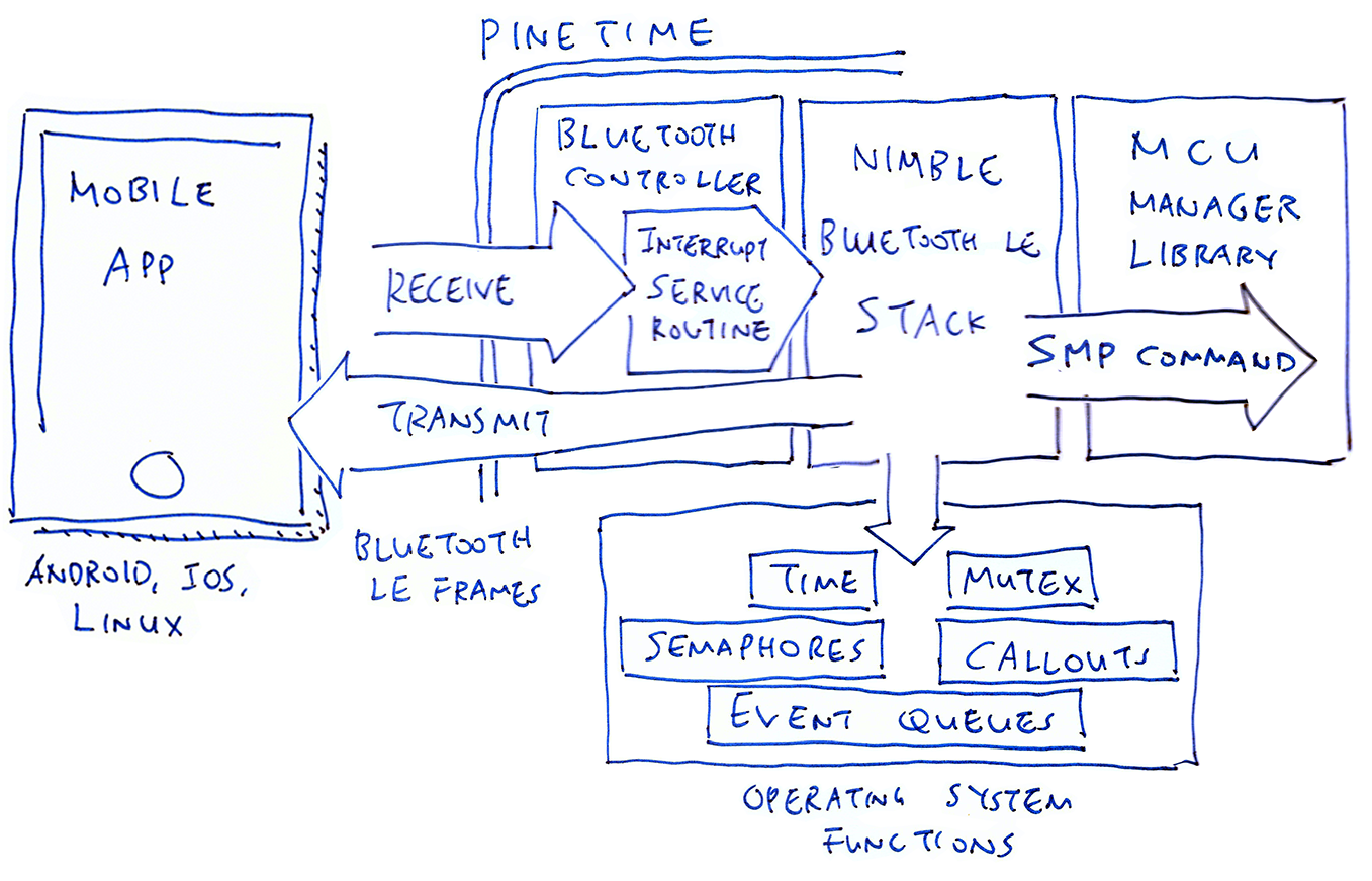
NimBLE Networking Stack for Bluetooth LE on PineTime
NimBLE runs in the background handling Bluetooth LE packets, so it depends on the multitasking capabilities provided by the operating system embedded in the firmware. This adaptation of NimBLE to the operating system happens in the NimBLE Porting Layer.
PineTime Firmware Developers would have to implement the NimBLE Porting Layer in C, covering these functions...
Time Functions: Get the elapsed time since startup, in milliseconds and in ticks (1 tick equals 1 millisecond)
Mutex Functions: When multiple tasks run at the same time on PineTime, they may clash when accessing common resources (like the Bluetooth hardware). NimBLE uses a Mutex (Mutually Exclusive Lock) to prevent concurrent access to common resources. More about Mutexes
Semaphore Functions: A Semaphore works like a Mutex but it's more flexible. Think of a Semaphore as a Ticket Queueing System for shared resources. More about Semaphores
Callout Functions: Callouts are deferred functions that will be executed after a specified time interval. More about Callouts
Event Queue Functions: Event Queues allow a task to delegate processing steps (i.e. Events) to one or more queues and tasks. More about Event Queues
Interrupt Functions: For managing interrupts
We'll see the list of functions at the end of this section.
What if our embedded operating system doesn't support Mutex / Semaphore / Callout / Event Queue?
It may be possible to emulate the missing functions using the multitasking features found in our operating system. Or we may implement them using simple counters and locks.
Let's check out how the NimBLE Porting Layer was implemented on various operating systems...
RIOT: Callouts are not supported in RIOT, so they are implemented with a combination of RIOT Timers and Event Queues. See riot/nimble_npl_os.h and npl_os_riot.c from the NimBLE Porting Layer for RIOT
FreeRTOS: Callouts are also implemented with Timers and Queues in FreeRTOS. Mutexes are implemented with FreeRTOS Semaphores. See freertos/nimble_npl_os.h from the NimBLE Porting Layer for FreeRTOS
MicroPython: Mutexes, Semaphores, Callouts and Event Queues don't exist in MicroPython, so they are implemented using simple counters and locks. See micropython/nimble_npl_os.h and npl_os.c from the NimBLE Porting Layer for MicroPython
Mynewt: NimBLE was created originally for Mynewt. Thus Mutexes, Semaphores, Callouts and Event Queues are used directly from Mynewt. See mynewt/nimble_npl_os.h from the NimBLE Porting Layer for Mynewt
For porting NimBLE to Real Time Operating Systems, we may use NimBLE Porting Layer for RIOT as the reference.
Otherwise we may use the NimBLE Porting Layer for MicroPython.
What is the Interrupt Service Routine in the diagram above?
When PineTime receives a Bluetooth LE data packet, the Bluetooth hardware controller triggers an Interrupt. The Interrupt Service Routine is the function provided by NimBLE to handle that Interrupt.
The Interrupt Service Routine forwards all received packets to the NimBLE background task for processing. We'll see in a while how NimBLE calls the NimBLE Porting Layer to set the Interrupt Service Routine.
Why does NimBLE need Event Queues?
The NimBLE Interrupt Service Routine runs at a higher priority than normal tasks (because handling interrupts needs to be super urgent). But it shouldn't hog the CPU and process the received Bluetooth packet immediately... That wouldn't be fair to other tasks!
Hence the NimBLE Interrupt Service Routine defers the processing of the received Bluetooth packet by adding it to an Event Queue. Another NimBLE task (running at normal priority) will pick up the Bluetooth packet and process it.
How shall we start the NimBLE Stack and listen for firmware update commands?
PineTime Firmware Developers would have to call the C function start_ble() defined in ble_main.c
This starts the NimBLE Stack to listen for SMP firmware update commands transmitted over GATT. The GATT command handlers for SMP are defined in ble_prph.h,
ble_gatt_svr.c,
ble_misc.c and
ble_phy.c
Here are the types and functions in the NimBLE Porting Layer that would be implemented by the PineTime Firmware Developer...
| Function | Description | Documentation |
|---|---|---|
struct ble_npl_mutex | Contains the OS-specific Mutex | See os_mutex |
struct ble_npl_sem | Contains the OS-specific Semaphore | See os_sem |
struct ble_npl_callout | Contains the OS-specific Callout | See os_callout |
struct ble_npl_event | Contains the OS-specific Event | See os_event |
struct ble_npl_eventq | Contains the OS-specific Event Queue | See os_eventq |
typedef ble_npl_time_t | OS-specific unsigned type that represents elapsed time, like uint32_t | |
typedef ble_npl_stime_t | OS-specific signed type that represents elapsed time, like int32_t |
| Function | Description | Documentation |
|---|---|---|
bool ble_npl_os_started() | Return true if OS has started and is ready to run tasks | See os_started in os.h and os_arch_arm.c |
void * ble_npl_get_current_task_id() | Returns the currently running task | See os_sched_get_current_task |
| Function | Description | Documentation |
|---|---|---|
ble_npl_error_t ble_npl_mutex_init( struct ble_npl_mutex *mu) | Create a Mutex and initialise it | See os_mutex_init(&mu->mu) |
ble_npl_error_t ble_npl_mutex_pend( struct ble_npl_mutex *mu, ble_npl_time_t timeout) | Wait for a Mutex | See os_mutex_pend(&mu->mu, timeout) |
ble_npl_error_t ble_npl_mutex_release( struct ble_npl_mutex *mu) | Release a Mutex | See os_mutex_release(&mu->mu) |
| Function | Description | Documentation |
|---|---|---|
ble_npl_error_t ble_npl_sem_init( struct ble_npl_sem *sem, uint16_t tokens) | Create a Semaphore and initialise it | See os_sem_init(&sem->sem, tokens |
ble_npl_error_t ble_npl_sem_pend( struct ble_npl_sem *sem, ble_npl_time_t timeout) | Wait for a Semaphore | See os_sem_pend(&sem->sem, timeout) |
ble_npl_error_t ble_npl_sem_release( struct ble_npl_sem *sem) | Release a Semaphore | See os_sem_release(&sem->sem) |
uint16_t ble_npl_sem_get_count( struct ble_npl_sem *sem) | Get the Semaphore's current count | See os_sem_get_count(&sem->sem) |
| Function | Description | Documentation |
|---|---|---|
void ble_npl_callout_init( struct ble_npl_callout *co, struct ble_npl_eventq *evq, ble_npl_event_fn *ev_cb, void *ev_arg) | Create a Callout and initialise it | See os_callout_init(&co->co, &evq->evq, ev_cb, ev_arg) |
ble_npl_error_t ble_npl_callout_reset( struct ble_npl_callout *co, ble_npl_time_t ticks) | Reset the callout to fire off in ticks ticks | See os_callout_reset(&co->co, ticks) |
void ble_npl_callout_stop( struct ble_npl_callout *co) | Stop the Callout from firing off, any pending events will be cleared | See os_callout_stop(&co->co) |
bool ble_npl_callout_is_active( struct ble_npl_callout *co) | Returns whether the Callout is pending or not | See os_callout_queued(&co->co) |
ble_npl_time_t ble_npl_callout_get_ticks( struct ble_npl_callout *co) | Number of ticks in the future to expire the Callout | See co->co.c_ticks |
ble_npl_time_t ble_npl_callout_remaining_ticks( struct ble_npl_callout *co, ble_npl_time_t time) | Returns the number of ticks which remains till Callout | See os_callout_remaining_ticks(&co->co, time) |
void ble_npl_callout_set_arg( struct ble_npl_callout *co, void *arg) | Set the argument that will be passed to the Callout callback | See co->co.c_ev.ev_arg |
| Function | Description | Documentation |
|---|---|---|
void ble_npl_eventq_init( struct ble_npl_eventq *evq) | Create an Event Queue and initialise it | See os_eventq_init(&evq->evq) |
struct ble_npl_event * ble_npl_eventq_get( struct ble_npl_eventq *evq, ble_npl_time_t tmo) | Pull a single Event from an Event Queue | See this note |
void ble_npl_eventq_put( struct ble_npl_eventq *evq, struct ble_npl_event *ev) | Put an Event on the Event Gueue | See os_eventq_put(&evq->evq, &ev->ev) |
void ble_npl_eventq_remove( struct ble_npl_eventq *evq, struct ble_npl_event *ev) | Remove an Event from the Event Queue | See os_eventq_remove |
void ble_npl_event_init( struct ble_npl_event *ev, ble_npl_event_fn *fn, void *arg) | Create an Event and initialise it | See this note |
bool ble_npl_event_is_queued( struct ble_npl_event *ev) | Return true if the Event is queued on an Event Queue | See ev->ev.ev_queued |
void * ble_npl_event_get_arg( struct ble_npl_event *ev) | Return the argument that will be passed to the Event Queue callback | See ev->ev.ev_arg |
void ble_npl_event_set_arg( struct ble_npl_event *ev, void *arg) | Set the argument that will be passed to the Event Queue callback | See ev->ev.ev_arg |
bool ble_npl_eventq_is_empty( struct ble_npl_eventq *evq) | Return true if the Event Queue is empty | |
void ble_npl_event_run( struct ble_npl_event *ev) | Execute the Event callback | See ev->ev.ev_cb(&ev->ev) |
| Function | Description | Documentation |
|---|---|---|
ble_npl_time_t ble_npl_time_get() | Get the current OS time in ticks | See os_time_get() |
ble_npl_error_t ble_npl_time_ms_to_ticks( uint32_t ms, ble_npl_time_t *out_ticks) | Converts milliseconds to OS ticks | See os_time_ms_to_ticks(ms, out_ticks) |
ble_npl_error_t ble_npl_time_ticks_to_ms( ble_npl_time_t ticks, uint32_t *out_ms) | Converts OS ticks to milliseconds | See os_time_ticks_to_ms(ticks, out_ms) |
ble_npl_time_t ble_npl_time_ms_to_ticks32( uint32_t ms) | Converts milliseconds to OS ticks | See os_time_ms_to_ticks32(ms) |
uint32_t ble_npl_time_ticks_to_ms32( ble_npl_time_t ticks) | Converts OS ticks to milliseconds | See os_time_ticks_to_ms32(ticks) |
void ble_npl_time_delay( ble_npl_time_t ticks) | Puts the current task to sleep for the specified number of os ticks | See os_time_delay(ticks) |
| Function | Description | Documentation |
|---|---|---|
void ble_npl_hw_set_isr( int irqn, void (*addr)(void)) | Set the Interrupt Service Routine for interrupt irqn to addr | See the RIOT implementation of ble_npl_hw_set_isr in nrf5x_isr.c |
uint32_t ble_npl_hw_enter_critical() | Disable interrupts | See os_arch_save_sr() |
void ble_npl_hw_exit_critical( uint32_t ctx) | Enable interrupts | See os_arch_restore_sr(ctx) |
bool ble_npl_hw_is_in_critical() | Returns true if interrupts are disabled | |
The complete list of NimBLE Porting Library functions to be implemented by PineTime Firmware Developers may be found in nimble_npl.h
The documentation above was derived from mynewt/nimble_npl_os.h from the NimBLE Porting Layer for Mynewt
We have covered two software components necessary for rolling out PineTime firmware updates over Bluetooth LE...
MCU Manager Library: Implements the Simple Management Protocol for updating firmware
NimBLE Bluetooth Stack: Implements the Bluetooth LE network transport for communicating with mobile phones
Now we'll cover the third and final open-source component: MCUBoot Bootloader. When PineTime has been configured for firmware update, the MCUBoot Bootloader is the first thing that PineTime executes when booting.
MCUBoot (coded in C) plays a critical role in the firmware update process... During firmware update, MCUBoot swaps the old and new firmware images (and swaps them back if the new firmware fails to start)
What's inside the Firmware Image?
For flashing firmware over Bluetooth, PineTime Firmware Developers would have to generate a Firmware Image File with this layout that MCUBoot understands...
| ROM Address | Offset in Image File | Size in bytes | Contents |
|---|---|---|---|
0x8000 | 0x0000 | 32 (0x20) | Image Header |
0x8020 | 0x0020 | 216 (0xD8) | Interrupt Vector Table |
0x80F8 | 0x00F8 | Firmware Code and Data | |
This layout looks clearer when we peek inside a Firmware Image File my_sensor_app.img with the command...
od -A x -t x1 my_sensor_app.img
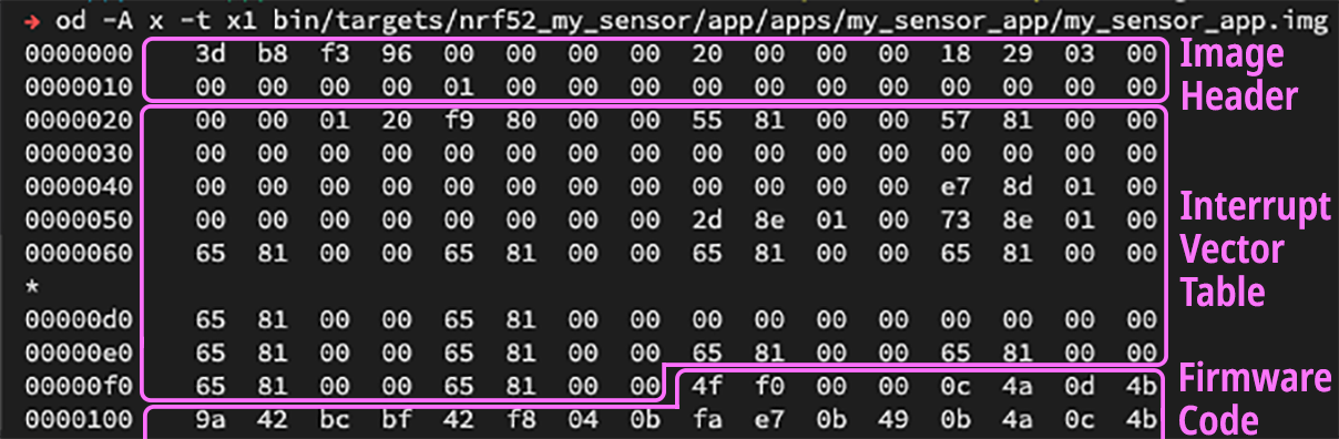
What's inside the Image Header?
The Image Header consists of 32 bytes (0x20) in little endian byte order (as defined here)...
| ROM Address | Offset in Image File | Size (bytes) | Example | Contents |
|---|---|---|---|---|
0x8000 | 0x0000 | 4 | 3d b8 f3 96 | ih_magic: Magic Number, must be 3d b8 f3 96 |
0x8004 | 0x0004 | 4 | 00 00 00 00 | ih_load_addr: Must be 00 00 00 00 |
0x8008 | 0x0008 | 2 | 20 00 | ih_hdr_size: Size of image header, must be 32 ( 0x20) |
0x800A | 0x000A | 2 | 00 00 | ih_protect_tlv_size: Size of protected TLV area, in bytes. Usually 00 00 |
0x800C | 0x000C | 4 | 18 29 03 00 | ih_img_size: Size of firmware image, in bytes. Does not include header. In this example, 0x032918 = 207,128 bytes |
0x8010 | 0x0010 | 4 | 00 00 00 00 | ih_flags: IMAGE_F_[...] flags, usually 00 00 00 00 |
0x8014 | 0x0014 | 1 | 01 | ih_ver.iv_major: Major version number |
0x8015 | 0x0015 | 1 | 00 | ih_ver.iv_minor: Minor version number |
0x8016 | 0x0016 | 2 | 00 00 | ih_ver.iv_revision: Revision number |
0x8018 | 0x0018 | 4 | 00 00 00 00 | ih_ver.iv_build_num: Build number |
0x801C | 0x001C | 4 | 00 00 00 00 | _pad1: Padding, must be 00 00 00 00 |
How shall we generate a Firmware Image that contains the Image Header?
MCUBoot provides a script imgtool.py (located here) that generates a Firmware Image using the Firmware ELF File produced by the GCC Compiler.
More about imgtool.py in the next section.
How does MCUBoot know if the new firmware is bad... And needs to be rolled back to the old firmware?
PineTime Firmware Developers need to set the Firmware OK status when the new firmware is running fine.
During startup, MCUBoot checks the Firmware OK status. If the Firmware OK status is missing, it rolls back to the old firmware.
More about the Firmware OK status later.
When shall we mark the new firmware as OK?
When new firmware runs on PineTime, it shall display a message prompt to indicate that the new firmware is indeed running...
"Mynewt on PineTime has been updated to version 2.0.1"
When the user taps OK, the firmware shall write the Firmware OK status.
This ensures that the new firmware is able to start up, display messages and accept input properly.
Do we need to build MCUBoot ourselves?
Good news for PineTime Firmware Developers: We don't need to build MCUBoot ourselves or link it with our firmware... Just use the Common Build of MCUBoot Bootloader that I have prepared!
pinetime-rust-mynewt/releases/tag/v4.0.1
This build of MCUBoot (mynewt.elf.bin) assumes that the PineTime firmware follows the Flash ROM Map described earlier in this article. The MCUBoot image should be flashed to PineTime at address 0x0.
Here are the build settings and build script for MCUBoot: targets/nrf52_boot, build-boot.sh
MCUBoot may be flashed to PineTime with these OpenOCD scripts: flash-boot.sh, flash-boot.ocd
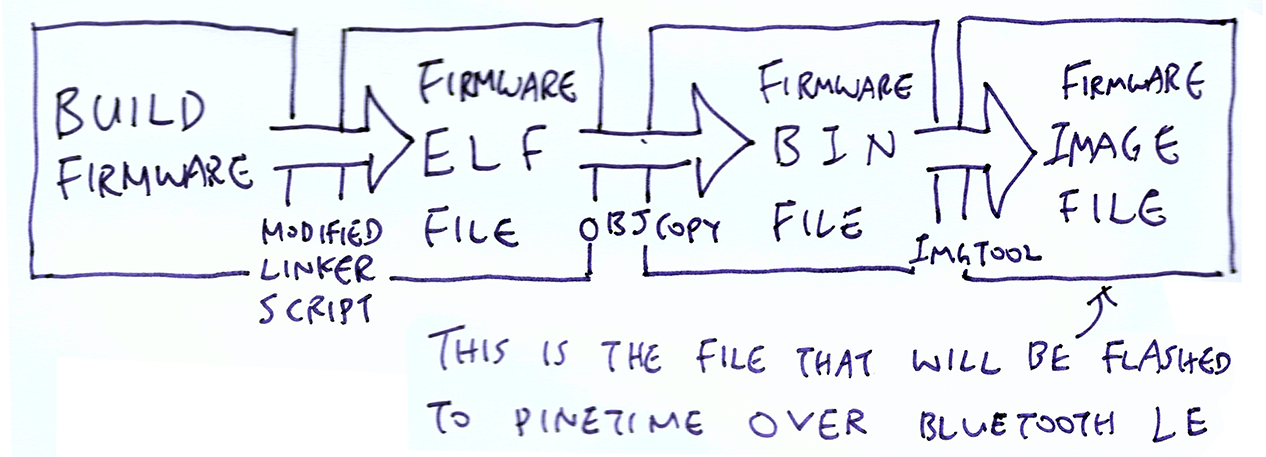
To flash PineTime over Bluetooth LE, PineTime Firmware Developers would have to create a Firmware Image File that includes the Image Header (used by MCUBoot for swapping firmware images).
Here are the steps for creating the Firmware Image File...
Modify the GCC Linker Script for our firmware to include the Image Header
Build our firmware with the modified Linker Script to create a Firmware ELF File
Convert the ELF file to a Firmware BIN File with arm-none-eabi-objcopy
Convert the BIN file to a Firmware Image File with MCUBoot's imgtool.py script
Thus the flow goes like this...
How shall we modify the GCC Linker Script for our firmware to include the Image Header?
For building our firmware, we'll modify our Linker Script like this (See nrf52.ld and nrf52xxaa.ld)
_imghdr_size = 0x20;

MEMORY
{
  FLASH (rx) : ORIGIN = 0x00008000, LENGTH = 464K
  RAM (rwx)  : ORIGIN = 0x20000000, LENGTH = 64K
}

SECTIONS
{
    .imghdr (NOLOAD):
    {
        . = . + _imghdr_size;
    } > FLASH

    __text = .;

    .text :
    {
        __isr_vector_start = .;
        KEEP(*(.isr_vector))
        __isr_vector_end = .;
        *(.text*)
This Linker Script says...
The usable Flash ROM (FLASH) starts at address 0x8000 with size 464 KB. RAM starts at address 0x2000 0000 with size 64 KB.
At the beginning of the Firmware Image in Flash ROM (FLASH), reserve 32 bytes (_imghdr_size) for the Image Header (.imghdr)
After the Image Header, write the Text Section (.text) into the Firmware Image. The Text Section contains the firmware code and data.
At the start of the Text Section, write out the standard Interrupt Vector Table (.isr_vector), which has 216 bytes (0xD8)
When GCC links our firmware with the above Linker Script, it produces a Firmware ELF File that has the following layout...
/* Section   Address      Size */
.imghdr      0x8000       0x20
.text        0x8020    0x32578
 .isr_vector 0x8020       0xd8
             0x80f8 Reset_Handler
In the example above, Reset_Handler is the first function in our firmware. That's why it was allocated address 0x80f8.
How shall we convert the Firmware ELF File to a Firmware BIN File?
To create the Firmware BIN File my_sensor_app.elf.bin from the Firmware ELF File my_sensor_app.elf, we run arm-none-eabi-objcopy (documented here)...
arm-none-eabi-objcopy \
    -R .bss \
    -R .bss.core \
    -R .bss.core.nz \
    -O binary \
    my_sensor_app.elf \
    my_sensor_app.elf.bin
(Refer to my_sensor_app.elf.cmd)
arm-none-eabi-objcopy takes an ELF file compiled for Arm Cortex-M and copies the binary sections (code and data) to the BIN file. It strips away the ELF headers and other metadata that are not required at runtime.
We use the -R option to remove unwanted ELF sections from the Firmware BIN File. The unwanted sections (like .bss.core) may be named differently for your embedded operating system.
How shall we convert the Firmware BIN File to a Firmware Image File?
MCUBoot provides a script imgtool.py (located here) that takes a Firmware BIN File and produces the Firmware Image File.
Here's how we generate the Firmware Image File my_sensor_app.img from a Firmware BIN File my_sensor_app.elf.bin...
# Install Python modules needed by imgtool.py
pip3 install --user -r mcuboot/scripts/requirements.txt

# Generate the Firmware Image File (including Image Header) from the Firmware BIN file
# Based on our updated Flash ROM Layout, the Firmware Image Slot Size is 464 KB (475,136 bytes)
mcuboot/scripts/imgtool.py create \
  --align 4 \
  --version 1.0.0 \
  --header-size 32 \
  --slot-size 475136 \
  --pad-header \
  my_sensor_app.elf.bin \
  my_sensor_app.img

# Verify the Firmware Image
mcuboot/scripts/imgtool.py verify my_sensor_app.img
# Should show:
# Image was correctly validated
# Image version: 1.0.0+0
This produces the Firmware Image File my_sensor_app.img that PineTime Owners may use to flash PineTime over Bluetooth LE.
In the above Linker Script, why is the Image Header (.imghdr) marked as NOLOAD?
NOLOAD means that the Image Header will NOT be written to the Firmware BIN File. Let's compare the Firmware BIN and Firmware Image Files...
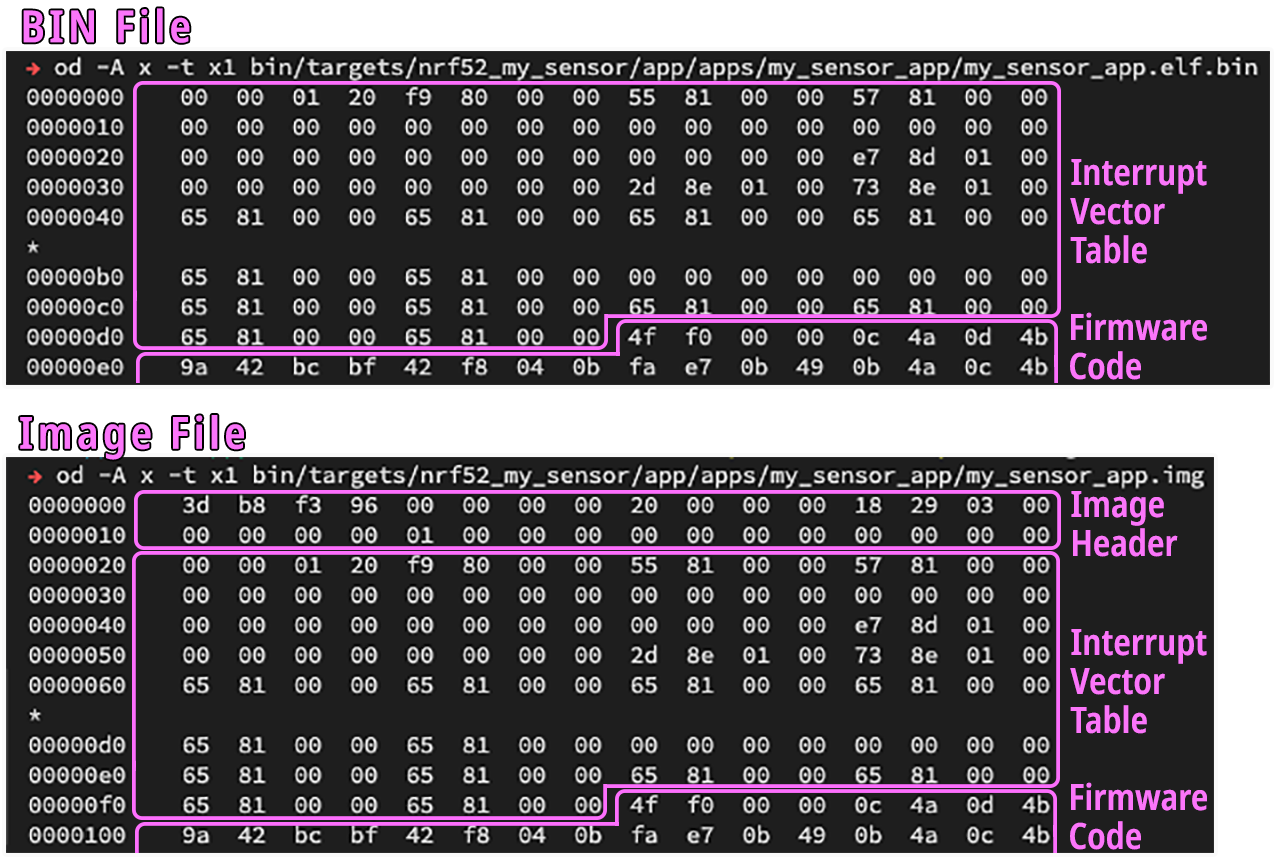
The files are identical... Just that the Firmware BIN File doesn't have the Image Header.
Thus when imgtool.py transforms the Firmware BIN File to a Firmware Image File... It's merely inserting the Image Header at the front of the BIN file!
That's why we use NOLOAD to drop the empty Image Header from the BIN file, and let imgtool.py insert a proper Image Header into the final firmware file.
Why not omit the Image Header from the Linker Script?
So that the GCC Linker can compute the ROM addresses correctly. Let's look again at the dumps of the Firmware BIN and Image Files...
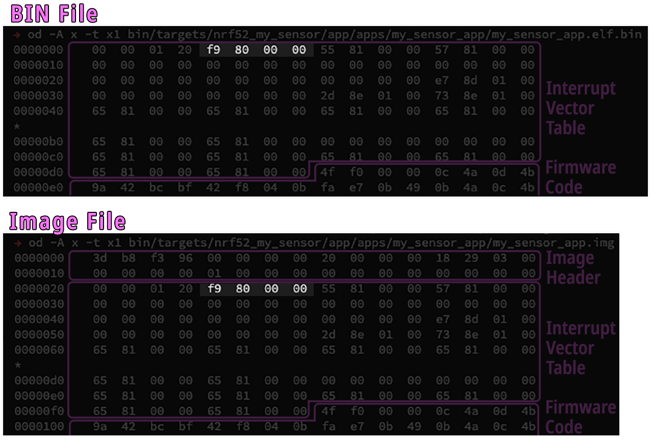
In both files, the Interrupt Vector Tables point to the Reset_Handler function, the first function in our firmware. The addresses in both Interrupt Vector Tables are the same: 0x80F9
But how did the GCC Linker allocate ROM address 0x80F9 for Reset_Handler? The offset (0xF9) was computed based on Image Header size (0x20) + Interrupt Vector Table size (0xD8) + 1.
Hence we had to insert an empty Image Header for GCC Linker to compute the correct ROM addresses.
BTW that's not a typo: The Interrupt Vector Table uses address 0x80F9 to refer to function Reset_Handler, which is actually located at 0x80F8 (i.e. the address is off by 1). This is a known quirk of Interrupt Vector Tables on Arm CPUs.
Are there sample Firmware ELF, BIN and Image Files available for inspection and testing?
Sample Firmware ELF (my_sensor_app.elf), BIN (my_sensor_app.elf.bin) and Image (my_sensor_app.img) Files may be found here...
pinetime-rust-mynewt/releases/tag/v4.0.1
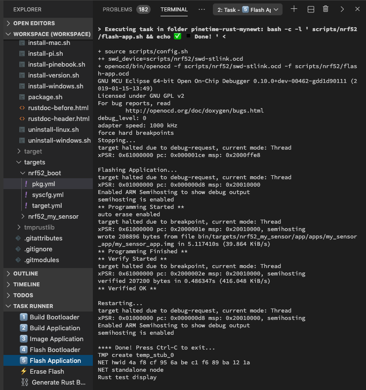
When running the firmware image with the build of MCUBoot from the previous section, the following log will be shown...
We need to set the Firmware Status to Pending so that MCUBoot will swap the firmware from External SPI Flash to Internal Flash ROM.
Here is the function boot_set_pending from the MCUBoot Library for setting the Firmware Status to Pending...
mcuboot/boot/bootutil/src/bootutil_public.c
The function sets the pending flag in the image trailer...
Once we set the Swap Type to BOOT_SWAP_TYPE_TEST, MCUBoot will swap in the new firmware.
MCUBoot Bootloader has a helpful feature that prevents PineTime from getting bricked during firmware update... When MCUBoot senses that the new firmware isn't running properly, MCUBoot rolls back PineTime to the old firmware.
How does MCUBoot know whether the new firmware is OK?
The new firmware is required to set the Image OK status in MCUBoot when it has started properly after a firmware update. This needs to be implemented by the PineTime Firmware Developer.
When shall we set the Image OK status?
Only when the new firmware is able to start up, display messages and accept input properly. See the MCUBoot section on the user confirmation prompt that shall be implemented by PineTime Firmware Developers.
How shall we set the Image OK status?
Call the C function boot_set_confirmed() from the MCUBoot Library...
//  Marks the image in the primary slot as confirmed.  The system will continue
//  booting into the image in the primary slot until told to boot from a
//  different slot. Returns 0 on success; nonzero on failure.
int boot_set_confirmed(void)
boot_set_confirmed() is supported on Mynewt, RIOT and Zephyr.
See bootutil_public.h and bootutil_public.c
Where is the Image OK status stored?
In the Image Trailer located at the end of the Active Flash Slot.
The Image OK field in the Image Trailer contains a single byte indicating whether the image in this slot has been confirmed as good by the user (0x01 means confirmed; 0xff means not confirmed).
The Image Trailer is not part of the Firmware Image. How does it get written?
During firmware update, MCUBoot writes the Image Trailer at the end of the Active Flash Slot.
To check whether there is a valid Image Trailer, MCUBoot looks for the following 16 "Magic" bytes (in host-byte-order)...
const uint32_t boot_img_magic[4] = {
  0xf395c277,
  0x7fefd260,
  0x0f505235,
  0x8079b62c };
More about the Image Trailer
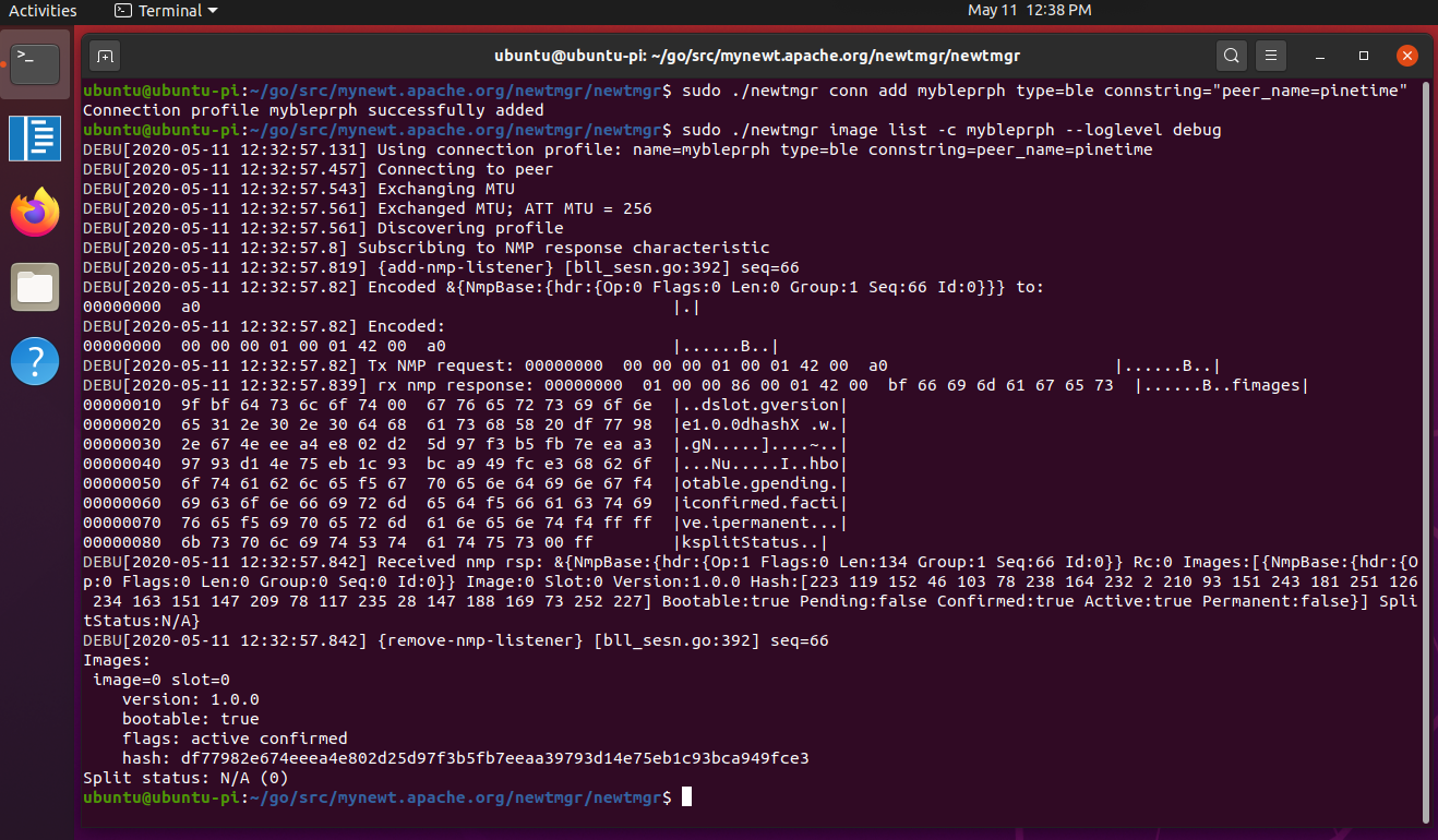
How do we inspect the Image OK status?
Use Newt Manager on Raspberry Pi. In the log below, image=0 slot=0 ... active confirmed means that the Active Firmware (Slot 0) is confirmed OK...
# Build Newt Manager on Raspberry Pi
$ cd ~/go
$ mkdir -p src/mynewt.apache.org
$ cd src/mynewt.apache.org/
$ git clone https://github.com/apache/mynewt-newtmgr
$ mv mynewt-newtmgr newtmgr
$ cd newtmgr/newtmgr
$ export GO111MODULE=on
$ go build

# Run Newt Manager on Raspberry Pi
$ cd ~/go/src/mynewt.apache.org/newtmgr/newtmgr
$ sudo ./newtmgr conn add mybleprph type=ble connstring="peer_name=pinetime"
Connection profile mybleprph successfully added

# Connect to PineTime and list firmware images
$ sudo ./newtmgr image list -c mybleprph --loglevel debug
Images:
 image=0 slot=0
    version: 1.0.0
    bootable: true
    flags: active confirmed
    hash: eab2886947a1df6f850463601f3dad409411d7ea21855eb0a70e965732258c92
Split status: N/A (0)
The complete Raspberry Pi log may be found near the end of the article.
More about the design of MCUBoot
In summary, PineTime Firmware Developers would have to do the following to support firmware updates over Bluetooth LE...
Adopt the Standard Flash ROM Layout for building the firmware, by modifying the GCC Linker Script
Port MCU Manager Library to the firmware, including the functions for writing the flash image to Flash ROM
Port NimBLE Bluetooth LE networking stack to the firmware by coding a NimBLE Porting Layer
Generate a Firmware Image containing Image Header in MCUBoot format with arm-none-eabi-objcopy and imgtool.py
When a new version of the firmware starts on PineTime, the firmware shall show the version number in a message prompt
When the user dismisses the message prompt, the firmware shall set the Image OK status
For Mynewt and Zephyr: Some of the steps in this article may not be necessary... Check the simpler porting instructions for Mynewt and Zephyr on the NimBLE, MCU Manager and MCUBoot websites.
When PineTime is configured for firmware update over Bluetooth LE, additional GATT Services may be exposed by the MCU Manager Library.
Here are the GATT Services that appear when the Nordic nRF Connect mobile app is connected to PineTime...
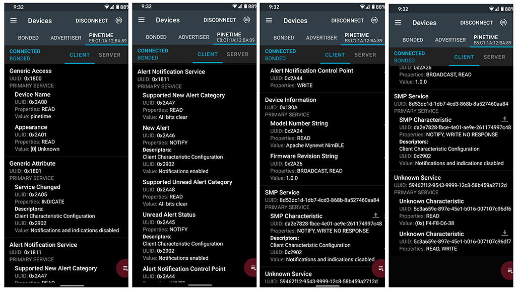
GATT Services exposed by MCU Manager on PineTime
Let's examine the GATT Services shown above...
Simple Management Protocol (SMP) Service (8D53DC1D-1DB7-4CD3-868B-8A527460AA84) is managed by the MCU Manager Library as Command Handlers...
Image Management: For querying and updating firmware images in PineTime's Flash ROM. This is the Command Handler that we have implemented to support firmware update on PineTime. See img_mgmt
File System Management: For accessing the user file system in PineTime's Flash ROM. See fs_mgmt
Log Management: For browsing the debugging messages logged by the firmware. See log_mgmt
OS Management: Execute Operating System functions. See os_mgmt
Statistics Management: Runtime statistics useful for troubleshooting. See stat_mgmt
PineTime Firmware Developers only need to implement the Image Management Command Handler to support firmware updates. The other Command Handlers are optional, though they may be useful for diagnostics and troubleshooting.
PineTime also exposes Standard GATT Services that are defined in the Bluetooth LE Specifications...
Generic Access (0x1800):
Device Name (pinetime) and Appearance. Specifications
Generic Attribute (0x1801): Notify the mobile app of any changes in PineTime's GATT Services.
Specifications
Device Information (0x180A): Model Number (Apache Mynewt NimBLE) and Firmware Revision (1.0.0).
Specifications
Alert Notification Service (0x1811): Alerts and Notifications.
Specifications
The final GATT Service (59462f12-9543-9999-12c8-58b459a2712d) in the screen above is the Security Test Service, which is also optional. See gatt_svr.c
We are now testing PineTime firmware update on Mynewt+Rust with the ota branch of pinetime-rust-mynewt...
Browse pinetime-rust-mynewt/ota repository
This branch of pinetime-rust-mynewt has the Newt Manager Library (Mynewt's version of the MCU Manager Library) injected here: my_sensor_app/src
(Look for the files ble_*.c and ble_*.h)
The source files were derived from the Mynewt bleprph sample. See bleprph
The Firmware ELF (my_sensor_app.elf), BIN (my_sensor_app.elf.bin) and Image (my_sensor_app.img) Files may be found here...
pinetime-rust-mynewt/releases/tag/v4.0.1
The built Firmware Image is 201 KB in size. Here are the sizes of each library linked into the firmware...
----- Build Mynewt and link with Rust app
+ newt build nrf52_my_sensor
Building target targets/nrf52_my_sensor
Linking /Users/Luppy/PineTime/pinetime-rust-mynewt/bin/targets/nrf52_my_sensor/app/apps/my_sensor_app/my_sensor_app.elf
Target successfully built: targets/nrf52_my_sensor
+ newt size -v nrf52_my_sensor
Size of Application Image: app
Mem FLASH: 0x8000-0x7bc00
Mem RAM: 0x20000000-0x20010000
  FLASH     RAM
    740     330 *fill*
   1018      98 apps_my_sensor_app.a
   1810     112 boot_bootutil.a
    438      26 boot_split.a
   1180       0 crypto_mbedtls.a
   2302       0 crypto_tinycrypt.a
    401       0 encoding_base64.a
   1622       0 encoding_cborattr.a
   3002       0 encoding_tinycbor.a
    440     444 hw_bsp_nrf52.a
     52       0 hw_cmsis-core.a
    706       1 hw_hal.a
   7074     154 hw_mcu_nordic_nrf52xxx.a
      2       0 hw_sensor_creator.a
   1264     260 hw_sensor.a
   8756   35712 kernel_os.a
   3044      50 libc_baselibc.a
     16       0 libs_mynewt_rust.a
  57400    9582 libs_rust_app.a
  12912       0 libs_rust_libcore.a
    738      42 libs_semihosting_console.a
     40       9 libs_sensor_coap.a
    583      99 libs_sensor_network.a
    677     212 libs_temp_stub.a
   3428      72 mgmt_imgmgr.a
    231      20 mgmt_mgmt.a
    884     100 mgmt_newtmgr.a
   1410      44 mgmt_newtmgr_nmgr_os.a
    454     108 mgmt_newtmgr_transport_ble.a
    405     388 net_oic.a
  35496    2107 nimble_controller.a
   4086    1203 nimble_drivers_nrf52.a
  41721    2797 nimble_host.a
    822     218 nimble_host_services_ans.a
    241     112 nimble_host_services_dis.a
    396     118 nimble_host_services_gap.a
    204      62 nimble_host_services_gatt.a
   1814     648 nimble_host_store_config.a
    114       0 nimble_host_util.a
    692    1096 nimble_transport_ram.a
   1578      54 sys_config.a
    634     128 sys_flash_map.a
      2       0 sys_log_modlog.a
    686      29 sys_mfg.a
    839      51 sys_reboot.a
    226      37 sys_sysdown.a
     30       5 sys_sysinit.a
   1746       0 time_datetime.a
    120       0 util_mem.a
    208       0 nrf52_my_sensor-sysinit-app.a
    166       0 libg.a
    968       0 libgcc.a
Loading compiler /Users/Luppy/PineTime/pinetime-rust-mynewt/repos/apache-mynewt-core/compiler/arm-none-eabi-m4, buildProfile debug

objsize
   text    data     bss     dec     hex filename
 205760     904   55224  261888   3ff00 /Users/Luppy/PineTime/pinetime-rust-mynewt/bin/targets/nrf52_my_sensor/app/apps/my_sensor_app/my_sensor_app.elf
[ UPDATE: Check out the followup article here ]
Based on feedback from the PineTime Community, the following enhancements are planned for the implementation of firmware updates...
Allow larger firmware images to be flashed: Based on the present Flash ROM Layout, the size of a firmware image may not exceed 232 KB. That's because we need to fit both Active and Standby Firmware Images into PineTime's 512 KB Flash ROM.
To support larger firmware images (up to 464 KB), we shall move the Standby Firmware Image to PineTime's External SPI Flash (4 MB).
Store Standby Firmware Image in External SPI Flash: MCUBoot shall be enhanced to swap firmware images across PineTime's Internal Flash ROM (512 KB) and External SPI Flash (4 MB).
MCUBoot shall access the External SPI Flash via Mynewt's driver for SPI Flash. See spiflash
Check out my article "Configure Mynewt for SPI Flash on PineTime Smart Watch (nRF52)"
PineTime Firmware Developers would also need to enhance the Image Management Command Handler (MCU Manager Library) to write firmware images to External SPI Flash (instead of Internal Flash). (Possibly based on Mynewt's spiflash driver)
Manual rollback of firmware images: We shall allow the PineTime Owner to roll back firmware images manually (in case the Owner decides that the new firmware isn't working properly).
To roll back the firmware manually when PineTime boots, press and hold the watch button for 5 seconds.
MCUBoot shall be enhanced to wait 5 seconds for the button press and to roll back the firmware.
PineTime Firmware Developers shall implement a Reboot or Watchdog feature, so that the Owner won't have to wait for the battery to drain completely before rolling back the firmware.
Allow flashing of firmware that doesn't implement firmware update: Implementing the firmware update functionality may not be feasible for some types of PineTime firmware. (Some firmware developers may get stuck at the NimBLE Porting Layer) Here's how we shall allow such firmware to be flashed...
As long as the firmware adopts the proposed Flash ROM Layout, and includes the MCUBoot Image Header, we shall allow the firmware to be flashed via PineTime's factory-installed firmware (which could be based on FreeRTOS, Mynewt, RIOT, Zephyr, ...)
To upgrade the firmware to a newer version, the PineTime Owner would have to rollback manually to the factory-installed firmware, then flash the upgraded firmware.
Bootloader Log: Log MCUBoot messages to the Arm Semihosting Console when PineTime's SWD port is connected. Useful for troubleshooting the bootloader.
To enable Semihosting Console in repos/mcuboot/boot/mynewt/src/main.c...
void os_msys_init(void); ///

int main(void) {
    hal_bsp_init();  //  Init Board Support Package
    os_msys_init();  //  Create pool of MSYS buffers used by Semihosting Console
    console_printf("Starting MCUBoot...\n");  //  Display a message
    console_flush(); //  Flush the message
Ensure that the same firmware version doesn't get flashed twice
For flashing PineTime over Bluetooth LE, we would need to find a suitable app for our mobile phones. The mobile app shall also be used to sync the current date/time with PineTime, also to forward notifications for display on PineTime.
The Nordic nRF Connect mobile app works fine for flashing PineTime... But it seems too complicated for most PineTime Owners.
Here's how we may build friendly apps for Android, iOS and Linux (e.g. PinePhone) mobile phones that will work with PineTime...
Firmware update on PineTime is based on the MCU Manager Library. We may use the Android MCU Manager Library (coded in Java) to build the Android app.
There is a similar libary for iOS: The iOS MCU Manager Library, coded in Swift.
Among all the MCU Manager Libraries, the iOS Swift version is easiest to understand because it calls high-level Bluetooth LE functions from the iOS Core Bluetooth API.
The source code is helpful for learning how MCU Manager composes a Simple Management Protocol (SMP) request over GATT.
To see how a GATT Request for firmware update is composed and transmitted, check out FirmwareUpgradeManager, ImageManager, McuManager and McuMgrBleTransport
Alternatively, we may build the Android and iOS apps in Flutter based on this Flutter library for Bluetooth LE: flutter_blue
We will have to code ourselves the GATT Requests for SMP (using the iOS Swift code as reference). But there's a huge benefit: This approach allows us to maintain a single code base (in Dart) to target both Android and iOS.
The Flutter app would also be a great reference for teaching how to talk to Bluetooth LE devices (like PineTime) and access GATT services, even though it won't look like a polished app.
Check out a sample Bluetooth LE app built with Flutter
For PinePhone and other Linux phones, we may reuse the code from the Newt Manager command-line tool.
Coded in Go, Newt Manager is the official command-line tool for performing all MCU Manager functions on PineTime, including firmware flashing and date/time synchronisation. See newtmgr_image and newtmgr_datetime
Newt Manager on Raspberry Pi 4 (Raspbian and Ubuntu) has been successfully tested with PineTime...
Newt Manager on 64-bit Ubuntu Desktop and Raspberry Pi 4, connected to PineTime via Bluetooth LE
The Newt Manager code in Go should be easy to wrap up with the GTK Library in Go, to create a GUI app for PinePhone and other Linux phones...
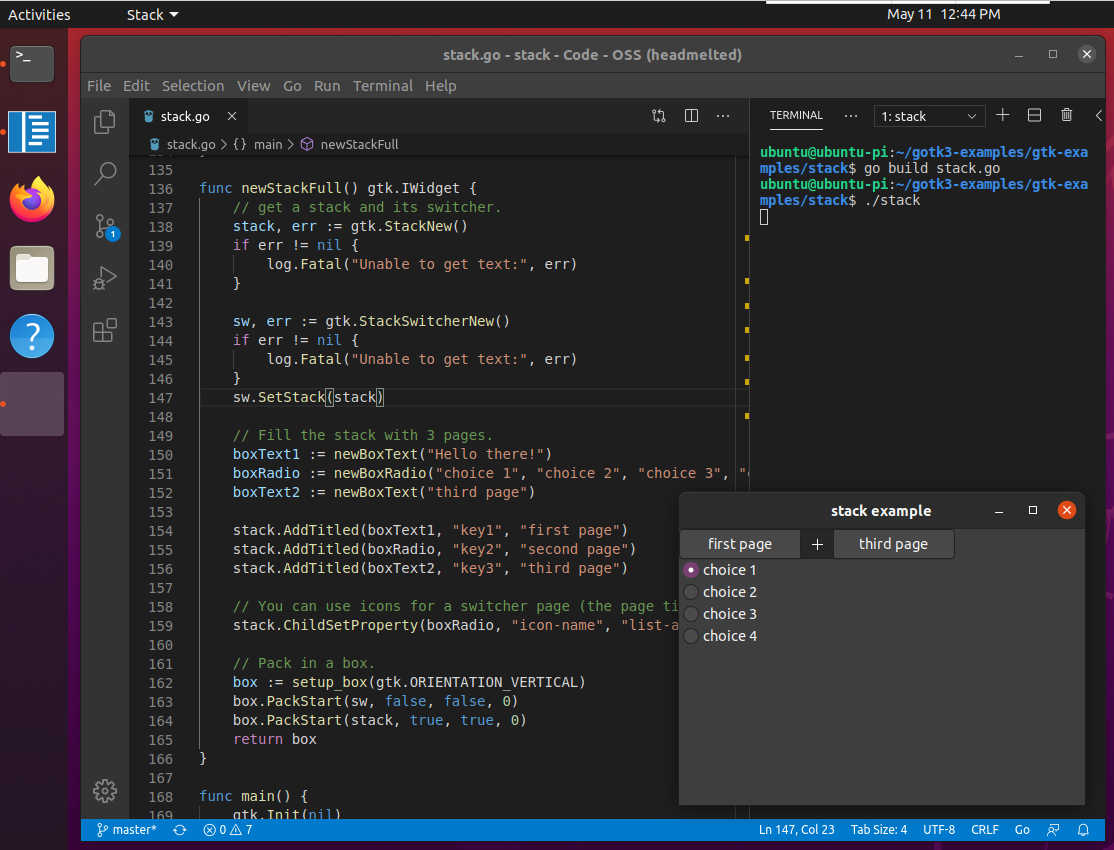
Developing a GTK app in Go with VSCode on 64-bit Ubuntu Desktop and Raspberry Pi 4. The compiled file size was 16 MB (Arm64).
See gotk3 and the sample GTK app
Here are the steps for building Newt Manager on Raspberry Pi 4 (Raspbian and Ubuntu) and connecting to PineTime. For Ubuntu, we will need to connect a USB Bluetooth dongle, since the onboard Bluetooth hardware is not supported.
# Build Newt Manager on Raspberry Pi
$ cd ~/go
$ mkdir -p src/mynewt.apache.org
$ cd src/mynewt.apache.org/
$ git clone https://github.com/apache/mynewt-newtmgr
$ mv mynewt-newtmgr newtmgr
$ cd newtmgr/newtmgr
$ export GO111MODULE=on
$ go build

# Run Newt Manager on Raspberry Pi
$ cd ~/go/src/mynewt.apache.org/newtmgr/newtmgr
$ sudo ./newtmgr conn add mybleprph type=ble connstring="peer_name=pinetime"
Connection profile mybleprph successfully added

# Connect to PineTime and list firmware images
$ sudo ./newtmgr image list -c mybleprph --loglevel debug
DEBU[2020-04-29 08:23:56.54] Using connection profile: name=mybleprph type=ble connstring=peer_name=pinetime
DEBU[2020-04-29 08:23:56.701] Connecting to peer
DEBU[2020-04-29 08:23:56.773] Exchanging MTU
DEBU[2020-04-29 08:23:56.822] Connecting to peer
DEBU[2020-04-29 08:23:56.907] Exchanging MTU
DEBU[2020-04-29 08:23:56.922] Exchanged MTU; ATT MTU = 256
DEBU[2020-04-29 08:23:56.922] Discovering profile
DEBU[2020-04-29 08:23:57.176] Subscribing to NMP response characteristic
DEBU[2020-04-29 08:23:57.191] {add-nmp-listener} [bll_sesn.go:392] seq=66
DEBU[2020-04-29 08:23:57.191] Encoded &{NmpBase:{hdr:{Op:0 Flags:0 Len:0 Group:1 Seq:66 Id:0}}} to:
00000000  a0                                                |.|
DEBU[2020-04-29 08:23:57.191] Encoded:
00000000  00 00 00 01 00 01 42 00  a0                       |......B..|
DEBU[2020-04-29 08:23:57.191] Tx NMP request: 00000000  00 00 00 01 00 01 42 00  a0                       |......B..|
DEBU[2020-04-29 08:23:57.213] rx nmp response: 00000000  01 00 00 86 00 01 42 00  bf 66 69 6d 61 67 65 73  |......B..fimages|
00000010  9f bf 64 73 6c 6f 74 00  67 76 65 72 73 69 6f 6e  |..dslot.gversion|
00000020  65 31 2e 30 2e 30 64 68  61 73 68 58 20 ea b2 88  |e1.0.0dhashX ...|
00000030  69 47 a1 df 6f 85 04 63  60 1f 3d ad 40 94 11 d7  |iG..o..c`.=.@...|
00000040  ea 21 85 5e b0 a7 0e 96  57 32 25 8c 92 68 62 6f  |.!.^....W2%..hbo|
00000050  6f 74 61 62 6c 65 f5 67  70 65 6e 64 69 6e 67 f4  |otable.gpending.|
00000060  69 63 6f 6e 66 69 72 6d  65 64 f5 66 61 63 74 69  |iconfirmed.facti|
00000070  76 65 f5 69 70 65 72 6d  61 6e 65 6e 74 f4 ff ff  |ve.ipermanent...|
00000080  6b 73 70 6c 69 74 53 74  61 74 75 73 00 ff        |ksplitStatus..|
DEBU[2020-04-29 08:23:57.214] Received nmp rsp: &{NmpBase:{hdr:{Op:1 Flags:0 Len:134 Group:1 Seq:66 Id:0}} Rc:0 Images:[{NmpBase:{hdr:{Op:0 Flags:0 Len:0 Group:0 Seq:0 Id:0}} Image:0 Slot:0 Version:1.0.0 Hash:[234 178 136 105 71 161 223 111 133 4 99 96 31 61 173 64 148 17 215 234 33 133 94 176 167 14 150 87 50 37 140 146] Bootable:true Pending:false Confirmed:true Active:true Permanent:false}] SplitStatus:N/A}
DEBU[2020-04-29 08:23:57.214] {remove-nmp-listener} [bll_sesn.go:392] seq=66
Images:
 image=0 slot=0
    version: 1.0.0
    bootable: true
    flags: active confirmed
    hash: eab2886947a1df6f850463601f3dad409411d7ea21855eb0a70e965732258c92
Split status: N/A (0)
Nordic SoftDevice includes a proprietary Bluetooth LE DFU implementation. More about SoftDevice
wasp-os with Adafruit NRF52 Bootloader (based on Nordic SoftDevice). More about wasp-os
[ UPDATE: Check out the followup article here ]
Got a question, comment or suggestion? Create an Issue or submit a Pull Request here...