📝 29 Jan 2021
PineCone BL602 (and Pinenut) is an awesome RISC-V Microcontroller Board with WiFi and Bluetooth LE Networking.
But to turn PineCone BL602 into an IoT Gadget we need one more thing…
An I2C Sensor!
Today we shall connect PineCone / Pinenut / Any BL602 Board to an I2C Sensor and read some data.
We shall also discover a feature that’s unique to BL602: I2C Register Addresses
Remember to check out the Appendix for Special Topics…
How to troubleshoot RISC-V Exceptions
How to test I2C Sensors with Bus Pirate
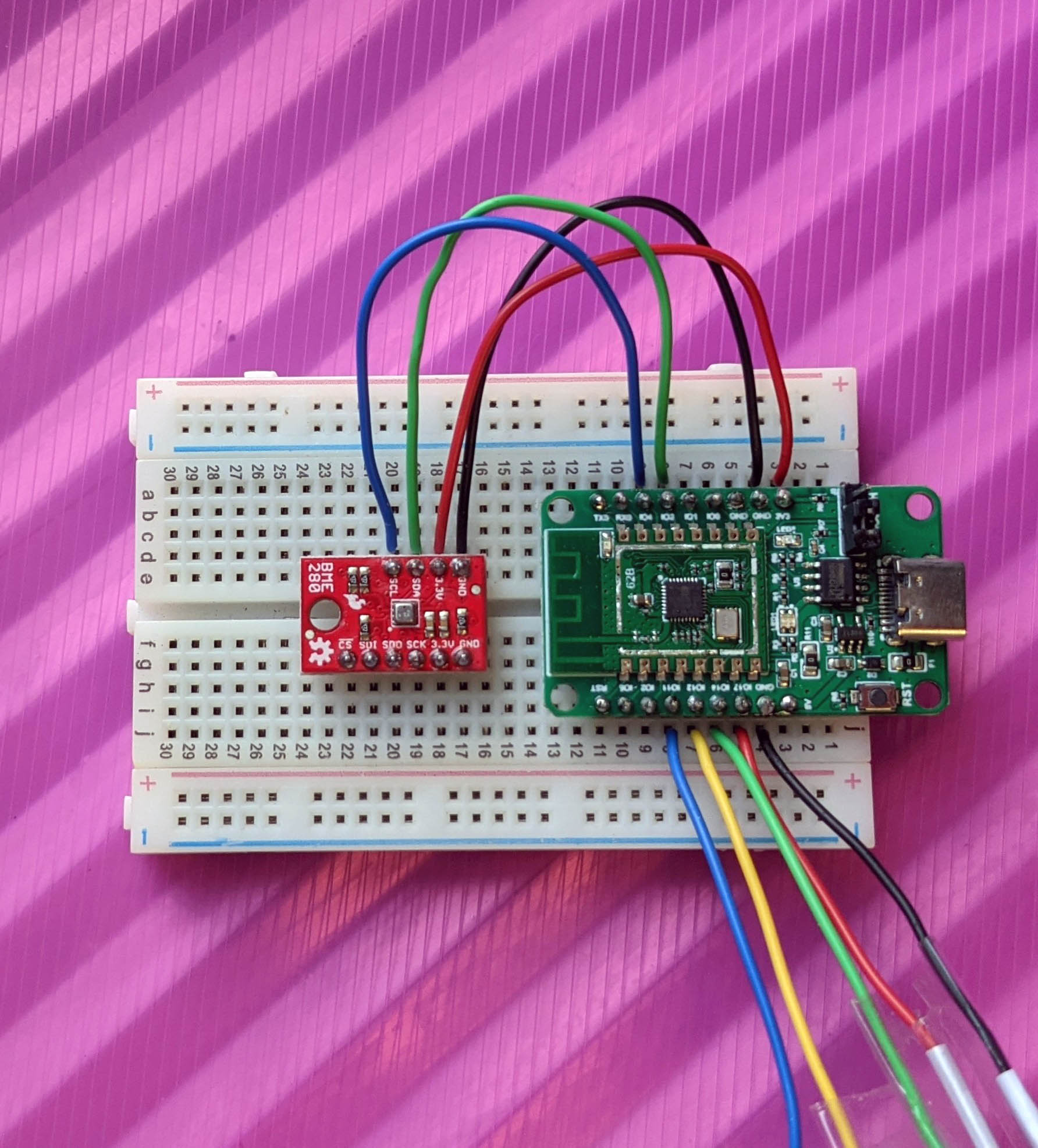
PineCone BL602 RISC-V Evaluation Board connected to BME280 I2C Sensor
BL602’s IoT SDK contains an I2C Hardware Abstraction Layer (HAL) that we may call in our C programs to access I2C Sensors.
BL602’s I2C HAL is packaged as two levels…
Low Level HAL bl_i2c.c: This runs on BL602 Bare Metal.
The Low Level HAL manipulates the BL602 I2C Registers directly to perform I2C functions.
High Level HAL hal_i2c.c: This calls the Low Level HAL, and uses the Device Tree and FreeRTOS.
The High Level HAL is called by the AliOS Firmware created by the BL602 IoT SDK.
(AliOS functions are easy to identify… Their function names begin with “aos_”)
(Why does the High Level HAL use FreeRTOS? We’ll learn in a while)
Today we shall use the Low Level I2C HAL bl_i2c.c because…
The Low Level I2C HAL is simpler to understand.
We’ll learn all about the BL602 I2C Hardware by calling the Low Level HAL Functions.
The Low Level I2C HAL works on all Embedded Operating Systems. (Not just FreeRTOS)
In the next article we’ll port the Low Level I2C HAL to Mynewt. And hopefully the PineCone BL602 Community will port it to Arduino, RIOT, Zephyr, …
But the Low Level I2C HAL is not functionally complete.
(Yes we said that BL602 will talk to I2C Sensors today… Though we won’t be able to use the sensor data meaningfully yet)
We’ll see in a while that the Low Level HAL requires an Embedded Operating System to function properly. (Which is beyond the scope of this article)
We shall test BL602 I2C with this BL602 Command-Line Firmware (modded from BL602 IoT SDK): sdk_app_i2c
(Don’t worry, we’ll make it hunky dory by the end of the article!)
The firmware will work on all BL602 boards, including PineCone and Pinenut.
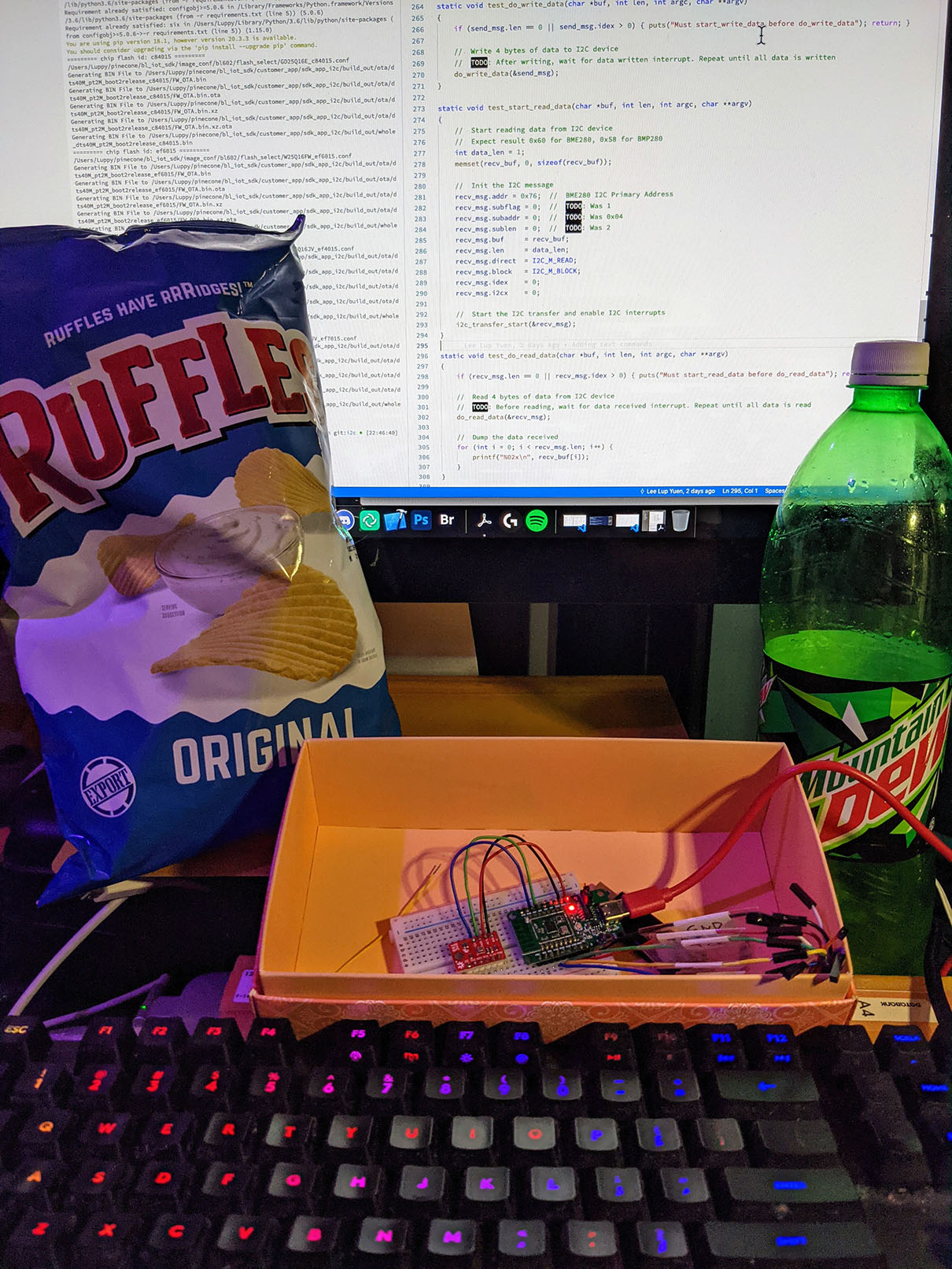
PineCone BL602 connected to SparkFun BME280 I2C Sensor
Let’s connect BL602 to the Bosch BME280 I2C Sensor for Temperature, Humidity and Air Pressure
(Air Pressure is very useful for sensing which level of a building we’re on!)
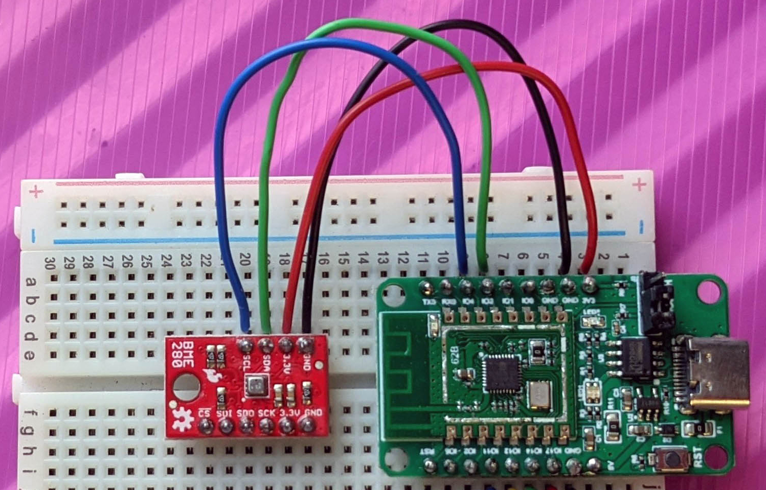
Connect BL602 to BME280 according to the pic above…
| BL602 Pin | BME280 Pin | Wire Colour |
|---|---|---|
GPIO 3 | SDA | Green |
GPIO 4 | SCL | Blue |
3V3 | 3.3V | Red |
GND | GND | Black |
(The steps in this article will work for BMP280 too)
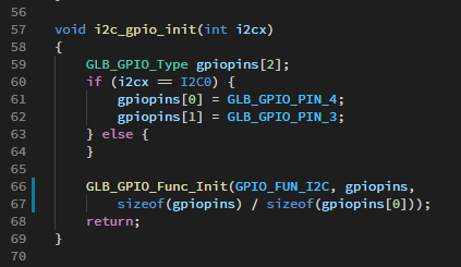
The Low Level I2C HAL assigns GPIO 3 and 4 to the I2C Port on BL602. (See “Section 3.2.8: GPIO Function” in the BL602 Reference Manual)
(If we’re using the High Level I2C HAL, the I2C Pins are defined in the Device Tree)
What shall we accomplish with BL602 and BME280?
We’ll access BME280 at I2C Device ID 0x77
(BME280 may be configured as Device ID 0x76 or 0x77. SparkFun BME280 in the pic above uses 0x77)
BME280 has an I2C Register, Chip ID, at Register 0xD0
Reading the Chip ID Register will give us the Chip ID value 0x60
(0x60 identifies the chip as BME280. For BMP280 the Chip ID is 0x58)
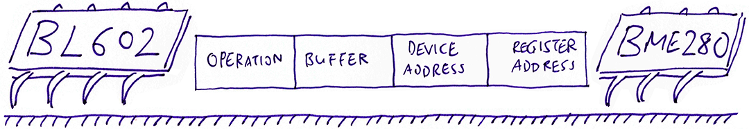
What are the data bytes that will be sent by BL602?
Here’s the I2C Data that will be sent by BL602 to BME280…
    [Start] 0xEE  0xD0  [Stop]

    [Start] 0xEF [Read] [Stop]
BL602 will initiate two I2C Transactions, indicated by [Start] ... [Stop]
In the First I2C Transaction, BL602 specifies the I2C Register to be read: 0xD0 (Chip ID)
In the Second I2C Transaction, BME280 returns the value of the Chip ID Register, indicated by [Read]
What are 0xEE and 0xEF?
They are the Read / Write aliases of the I2C Device ID 0x77…
0xEE = (0x77 * 2) + 0, for Writing Data
0xEF = (0x77 * 2) + 1, for Reading Data
I2C uses this even / odd convention to indicate whether we’re writing or reading data.
To sum up: We need to reproduce on BL602 the two [Start] ... [Stop] transactions. Which includes sending 3 bytes (0xEE, 0xD0, 0xEF) and receiving 1 byte (0x60).
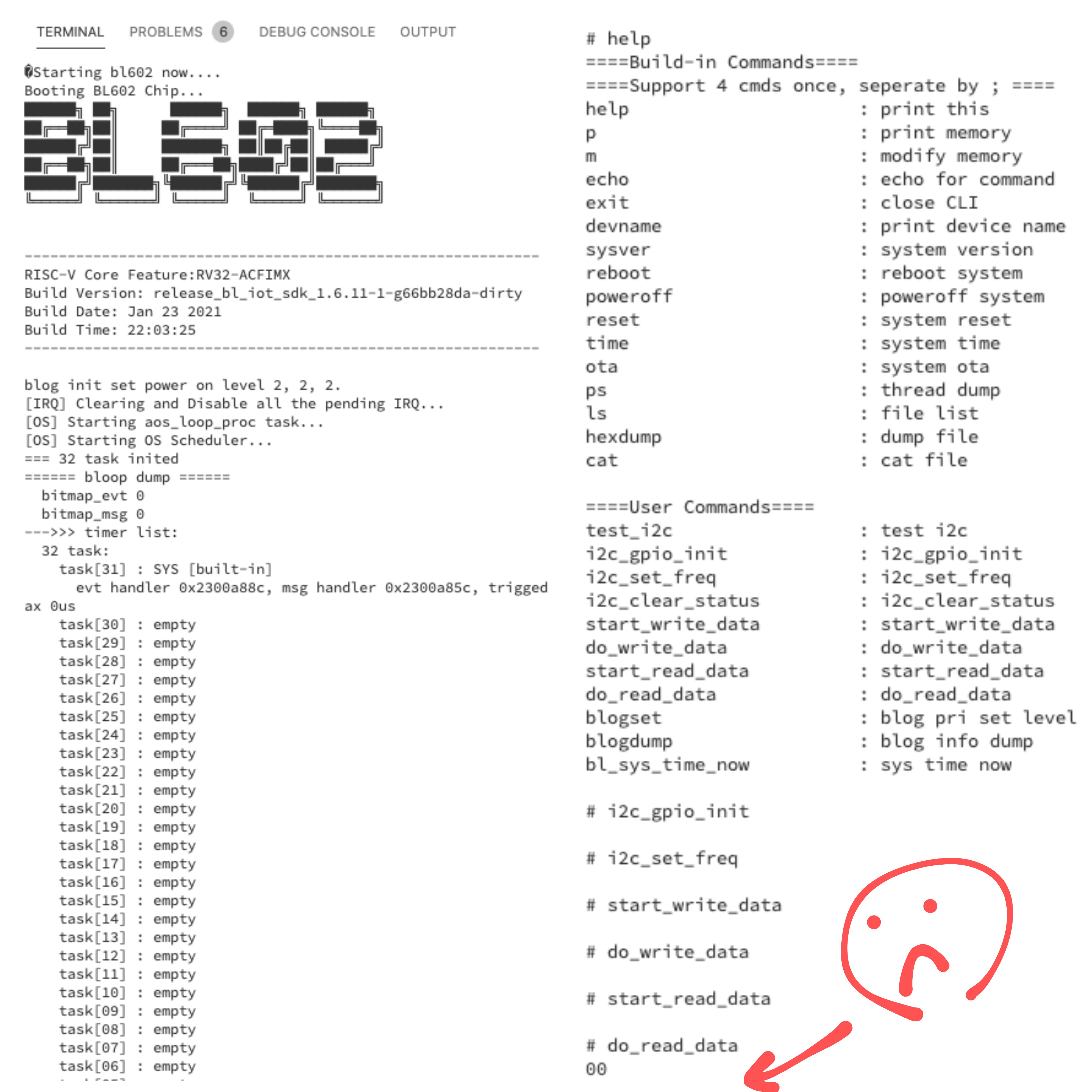
Remember our Command-Line Firmware sdk_app_i2c for testing I2C on BL602?
Here’s the command for initialising the I2C Port…
i2c_initLet’s discover how this command calls the Low Level I2C HAL to initialise the I2C Port: sdk_app_i2c/demo.c
/// Init I2C Port. Based on hal_i2c_init in hal_i2c.c
static void test_i2c_init(char *buf, int len, int argc, char **argv) {
    //  Use I2C Port 0
    const int i2cx = 0;
We’ll use I2C Port 0, the one and only I2C Port on BL602.
    //  Init I2C Port 0 to GPIO 3 and 4
    i2c_gpio_init(i2cx);

    //  Set I2C Port 0 to 500 kbps
    i2c_set_freq(500, i2cx);
We call i2c_gpio_init to assign GPIO 3 and 4 as the SDA and SCL pins for I2C Port 0.
Then we call i2c_set_freq to set the I2C Frequency to 500 kbps.
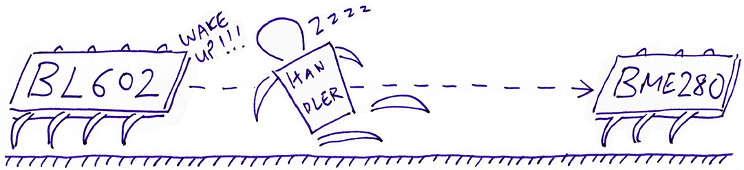
The I2C Port triggers I2C Interrupts after sending and receiving queued data, also when an error occurs. So we need to enable I2C Interrupts…
    //  Disable I2C Port 0
    I2C_Disable(i2cx);

    //  Enable I2C interrupts
    bl_irq_enable(I2C_IRQn);
    I2C_IntMask(i2cx, I2C_INT_ALL, MASK);
We disable the I2C Port, then enable I2C Interrupts on the I2C Port.
To handle I2C Interrupts we register an Interrupt Handler Function…
    //  Register the I2C Interrupt Handler
    bl_irq_register_with_ctx(
        I2C_IRQn,                  //  For I2C Interrupt:
        test_i2c_interrupt_entry,  //  Interrupt Handler
        &gpstmsg                   //  Pointer to current I2C Message
    );
}
Here we register the function test_i2c_interrupt_entry as the Interrupt Handler Function for I2C Interrupts. (More about this function in a while)
gpstmsg is the Interrupt Context that will be passed to the Interrupt Handler Function…
/// Global pointer to current I2C Message
static i2c_msg_t *gpstmsg;
gpstmsg points to the current I2C Message being sent or received, so that the Interrupt Handler knows which Message Buffer to use for sending and receiving data.
Let’s list down the HAL Functions called above and where they are defined…
The following functions are defined in the Low Level I2C HAL: bl_i2c.c
i2c_gpio_init, i2c_set_freqThese functions are defined in the BL602 Interrupt HAL: bl_irq.c
bl_irq_enable, bl_irq_register_with_ctxAnd these functions are defined in the BL602 Standard Driver: bl602_i2c.c
I2C_Disable, I2C_IntMask(The BL602 Standard Driver contains low-level functions to manipulate the BL602 Hardware Registers)
Our objective is to read Register 0xD0 from our BME280 Sensor with Device ID 0x77
We specify these details in an I2C Message Struct i2c_msg_t that’s defined in the Low Level I2C HAL.
Here’s how we create an I2C Message: sdk_app_i2c/demo.c
//  Define I2C message and buffer
static i2c_msg_t read_msg;    //  Message for reading I2C Data
static uint8_t read_buf[32];  //  Buffer for reading I2C Data
int data_len = 1;             //  Bytes to be read
First we define read_msg as a static I2C Message.
The data returned by our BME280 Sensor shall be stored in the static buffer read_buf.
//  Set the I2C operation
read_msg.i2cx   = 0;            //  I2C Port
read_msg.direct = I2C_M_READ;   //  Read I2C data
read_msg.block  = I2C_M_BLOCK;  //  Wait until data has been read
Next we set the I2C Port (0) and the I2C Operation (Blocking Read).
//  Set the I2C buffer
read_msg.buf  = read_buf;  //  Read buffer
read_msg.len  = data_len;  //  Number of bytes to be read
read_msg.idex = 0;         //  Index of next byte to be read into buf
Then we assign the data buffer read_buf to read_msg and set the number of bytes to be read (1).
idex is the index into the buffer read_buf. Our I2C Interrupt Handler will increment this index as it populates the buffer upon receiving data.
We’ll be reading data from BME280, which has Device ID 0x77.
We specify the Device Address like so…
//  Set device address
read_msg.addr = 0x77;  //  BME280 I2C Secondary Address (Primary Address is 0x76)
Now here’s the really really interesting thing about BL602…
Remember that we will be reading Register 0xD0 (Chip ID) on BME280?
We specify the Register Address in this incredibly easy peasy way…
//  Set register address
read_msg.subflag = 1;     //  Enable Register Address
read_msg.subaddr = 0xd0;  //  Register Address (BME280 Chip ID)
read_msg.sublen  = 1;     //  Length of Register Address (bytes)
This I2C Register Address feature is unique to BL602!
The I2C Register Address feature is not available on STM32 Blue Pill, Nordic nRF52, GigaDevice GD32 VF103 (RISC-V), ESP32, … Not even on Raspberry Pi Pico!
(Though it seems to be supported on NXP Microcontrollers as “I2C Subaddress”)
Thus BL602 I2C works a little differently from other microcontrollers.
This may complicate the support for I2C in Embedded Operating Systems like Mynewt, RIOT and Zephyr. (More about this in a while)
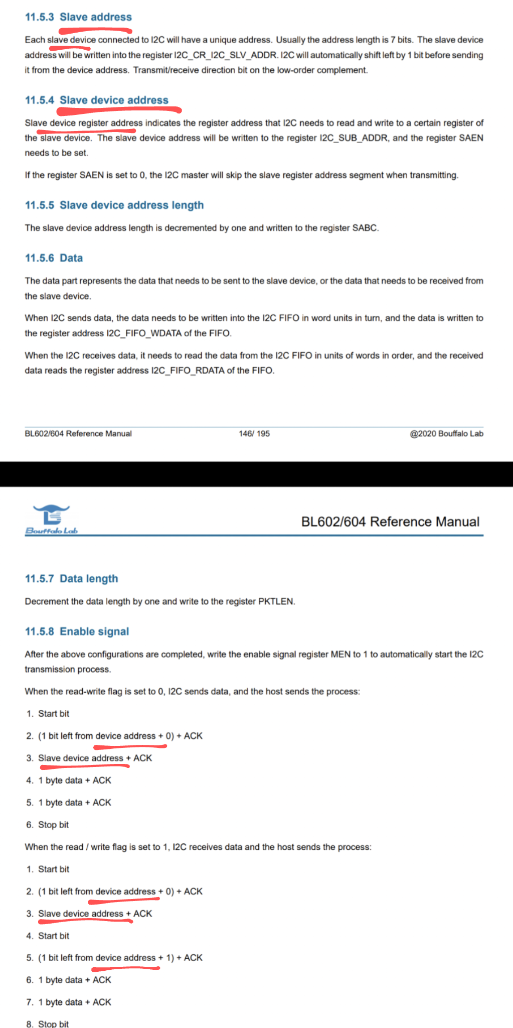
The I2C Documentation in the BL602 Reference Manual appears somewhat confusing because of the I2C Register Address feature. See this
In this article we shall standardise on these I2C Terms…
We say “Device Address”
(Instead of “Slave Address”, “Slave Device”)
We say “Register Address”
(Instead of “Subaddress”, “Slave Device Address”, “Slave Device Register Address”)
Now that we have created our I2C Message, let’s watch it in action!
To begin reading data from our BME280 Sensor, we enter this command…
i2c_start_readLet’s find out what happens inside that command: sdk_app_i2c/demo.c
We start by creating the I2C Message. We have seen this code earlier for creating the message…
//  Define I2C message and buffer
static i2c_msg_t read_msg;    //  Message for reading I2C Data
static uint8_t read_buf[32];  //  Buffer for reading I2C Data

static void test_i2c_start_read(char *buf, int len, int argc, char **argv) {
    //  Start reading data from I2C device
    //  Expect result 0x60 for BME280, 0x58 for BMP280
    int data_len = 1;  //  Bytes to be read
    memset(read_buf, 0, sizeof(read_buf));

    //  Set the I2C operation
    read_msg.i2cx    = 0;            //  I2C Port
    read_msg.direct  = I2C_M_READ;   //  Read I2C data
    read_msg.block   = I2C_M_BLOCK;  //  Wait until data has been read

    //  Set the I2C buffer
    read_msg.buf     = read_buf;     //  Read buffer
    read_msg.len     = data_len;     //  Number of bytes to be read
    read_msg.idex    = 0;            //  Index of next byte to be read into buf

    //  Set device address and register address
    read_msg.addr    = 0x77;   //  BME280 I2C Secondary Address (Primary Address is 0x76)
    read_msg.subflag = 1;      //  Enable Register Address
    read_msg.subaddr = 0xd0;   //  Register Address (BME280 Chip ID)
    read_msg.sublen  = 1;      //  Length of Register Address (bytes)
(For I2C Write Operation I2C_M_WRITE: The Message buffer field buf should point to a byte array that contains the I2C Data that will be written to the I2C Register)
Now we start the I2C data transfer…
    //  Start the I2C transfer and enable I2C interrupts
    gpstmsg = &read_msg;
    i2c_transfer_start(&read_msg);

    //  do_read_data will be called to read data
    //  in the I2C Interrupt Handler (test_i2c_transferbytes)
}
We point gpstmsg to our I2C Message. (Will be used for saving data into our buffer)
Then we call i2c_transfer_start to start the I2C data transfer and enable the I2C Interrupts.
i2c_transfer_start is defined in the Low Level I2C HAL: bl_i2c.c
How does BL602 receive the I2C data from our BME280 Sensor?
The I2C data transfer happens in the background, thanks to our I2C Interrupt Handler.
Our I2C Interrupt Handler receives the I2C data from the BME280 Sensor and populates our read buffer read_buf
Let’s go deep into our I2C Interrupt Handler…
Earlier we registered test_i2c_interrupt_entry as our Interrupt Handler for I2C Interrupts…
//  Register the I2C Interrupt Handler
bl_irq_register_with_ctx(
    I2C_IRQn,                  //  For I2C Interrupt:
    test_i2c_interrupt_entry,  //  Interrupt Handler
    &gpstmsg                   //  Pointer to current I2C Message
);
And the current I2C Message gpstmsg will be passed as our Interrupt Context.
Let’s find out how our Interrupt Handler handles I2C Interrupts: sdk_app_i2c/demo.c
When an I2C Interrupt is triggered, we fetch the Interrupt Reason and the I2C Message (from the Interrupt Context)…
/// I2C Interrupt Handler. Based on i2c_interrupt_entry in hal_i2c.c
static void test_i2c_interrupt_entry(void *ctx) {
// Fetch the current I2C Message from the Interrupt Context
i2c_msg_t *msg = *((i2c_msg_t **)ctx);
// Get the reason for the interrupt
uint32_t reason = BL_RD_REG(I2C_BASE, I2C_INT_STS);
// Handle each reason and increment the Interrupt Counters
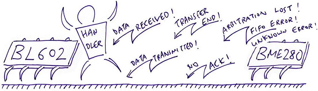
count_int++; // Overall interruptsAccording to the BL602 Reference Manual there are 6 kinds of I2C Interrupts…
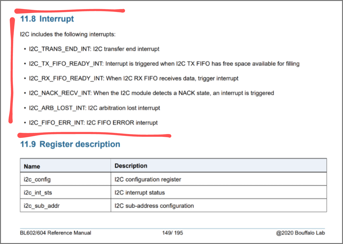
Some good… Some not so good. Let’s handle each type of interrupt…
(For I2C Read Operation)
When we receive data from our I2C Sensor… It’s good news!
    if (BL_IS_REG_BIT_SET(reason, I2C_RXF_INT)) {
        //  Receive FIFO Ready
        count_rfx++;
        msg->event = EV_I2C_RXF_INT;
        //  Should not return
This condition flows through to the end of our Interrupt Handler, and calls test_i2c_transferbytes to copy the received data into our Message Buffer and receive more data.
If the I2C data transfer is ending, we call test_i2c_stop to disable the I2C Port.
    } else if (BL_IS_REG_BIT_SET(reason, I2C_END_INT)) {
        //  Transfer End
        count_end++;
        msg->event = EV_I2C_END_INT;
        test_i2c_stop(msg);
        return;  //  Stop now
This condition quits our Interrupt Handler right away.
This is bad… We encounter I2C No Acknowledge usually when the I2C Device Address is misconfigured (say 0x76 instead of 0x77).
    } else if (BL_IS_REG_BIT_SET(reason, I2C_NAK_INT)) {
        //  No Acknowledge
        count_nak++;
        msg->event = EV_I2C_NAK_INT;
        test_i2c_stop(msg);
        return;  //  Stop now
We disable the I2C Port and quit the Interrupt Handler right away.
(For I2C Write Operation)
This is good, it means that the queued data has been transmitted…
    } else if (BL_IS_REG_BIT_SET(reason, I2C_TXF_INT)) {
        //  Transmit FIFO Ready
        count_txf++;
        msg->event = EV_I2C_TXF_INT;
        //  Should not return
This condition flows through to the end of our Interrupt Handler, and calls test_i2c_transferbytes to transmit the next 4 bytes of data from our Message Buffer.
Lastly we handle the remaining errors: Arbitration Lost, FIFO Error, Unknown Error…
    } else if (BL_IS_REG_BIT_SET(reason, I2C_ARB_INT)) {
        //  Arbitration Lost
        count_arb++;
        msg->event = EV_I2C_ARB_INT;
        test_i2c_stop(msg);
        return;  //  Stop now
    } else if (BL_IS_REG_BIT_SET(reason,I2C_FER_INT)) {
        //  FIFO Error
        count_fer++;
        msg->event = EV_I2C_FER_INT;
        test_i2c_stop(msg);
        return;  //  Stop now
    } else {
        //  Unknown Error
        count_unk++;
        msg->event = EV_I2C_UNKNOW_INT;
        test_i2c_stop(msg);
        //  Should not return
    }
We disable the I2C Port and quit the Interrupt Handler right away. (Except for Unknown Error)
For I2C Data Received and I2C Data Transmitted, our Interrupt Handler flows through to this code…
    //  For Receive FIFO Ready and Transmit FIFO Ready, transfer 4 bytes of data
    test_i2c_transferbytes(msg);
}
test_i2c_transferbytes does the following…
For I2C Read Operation: Copy the received data into our Message Buffer (4 bytes at a time) and receive more data.
For I2C Write Operation: Transmit the next 4 bytes of data from our Message Buffer.
More about this in the next section…

BL602 I2C has a FIFO Queue (First In First Out) of 4 bytes for transmitting and receiving I2C data.
Our I2C Interrupt Handler calls test_i2c_transferbytes to transmit and receive data in 4-byte chunks.
Here’s how it works for I2C Write and I2C Read Operations: sdk_app_i2c/demo.c
In an I2C Write Operation, we handle the I2C Data Transmitted Interrupt by transmitting the next 4 bytes from the Message Buffer…
/// For Rx FIFO Ready and Tx FIFO Ready, transfer 4 bytes of data.
/// Called by I2C Interrupt Handler. Based on i2c_transferbytes in hal_i2c.c
static void test_i2c_transferbytes(i2c_msg_t *msg) {
    //  For I2C Write Operation and I2C Data Transmitted Interrupt...
    if (msg->direct == I2C_M_WRITE && msg->event == EV_I2C_TXF_INT) {
        if (msg->idex < msg->len) {
            //  If there is buffer data to be transmitted, transmit 4 bytes from buffer
            do_write_data(msg);
        } else if (msg->idex == msg->len) {
            //  Otherwise suppress the Data Transmitted Interrupts
            I2C_IntMask(msg->i2cx, I2C_TX_FIFO_READY_INT, MASK);
        }
If there is no more data to be transmitted, we suppress the I2C Data Transmitted Interrupts.
do_write_data is defined in the Low Level I2C HAL: bl_i2c.c
In an I2C Read Operation, we handle the I2C Data Received Interrupt by copying the received bytes into the Message Buffer, 4 bytes at a time…
    //  For I2C Read Operation and I2C Data Received Interrupt...
    } else if (msg->direct == I2C_M_READ && msg->event == EV_I2C_RXF_INT) {
        if (msg->idex < msg->len) {
            //  If there is data to be received, copy 4 bytes into buffer
            do_read_data(msg);
        } else {
            //  Otherwise suppress the Data Received Interrupts
            I2C_IntMask(msg->i2cx, I2C_RX_FIFO_READY_INT, MASK);
        }
    }
}
If there is no more data to be received, we suppress the I2C Data Received Interrupts.
do_read_data is defined in the Low Level I2C HAL: bl_i2c.c
(FYI: test_i2c_transferbytes is the fixed version of i2c_transferbytes from the High Level I2C HAL hal_i2c.c. Here’s the fix)
Here’s the final command that we’ll enter into the BL602 Firmware… It terminates the I2C transfer.
i2c_stop_readThis command calls test_i2c_stop to close the I2C Port: sdk_app_i2c/demo.c
/// Stop reading data from I2C device
static void test_i2c_stop_read(char *buf, int len, int argc, char **argv) {
    //  Stop the I2C transfer on I2C Port 0
    test_i2c_stop(&read_msg);

    //  Dump the data received
    for (int i = 0; i < read_msg.len; i++) {
        printf("%02x\n", read_buf[i]);
    }
}
The command also dumps the data received in the I2C Message Buffer.
test_i2c_stop closes the I2C Port like so: sdk_app_i2c/demo.c
/// Stop the I2C Transfer. Called by I2C Interrupt Handler.
/// Based on i2c_callback in hal_i2c.c
static void test_i2c_stop(i2c_msg_t *msg) {
    //  Disable I2C Port
    I2C_Disable(msg->i2cx);

    //  Suppress all I2C Interrupts
    I2C_IntMask(msg->i2cx, I2C_INT_ALL, MASK);

    //  Clear any error status
    i2c_clear_status(msg->i2cx);
}
i2c_clear_status is defined in the Low Level I2C HAL: bl_i2c.c
Reading BME280 with sdk_app_i2c firmware
We’ve read the I2C code… Let’s download, flash and run the modded sdk_app_i2c firmware!
Download the Firmware Binary File sdk_app_i2c.bin from…
Alternatively, we may build the Firmware Binary File sdk_app_i2c.bin from the source code…
## Download the master branch of lupyuen's bl_iot_sdk
git clone --recursive --branch master https://github.com/lupyuen/bl_iot_sdk
cd bl_iot_sdk/customer_app/sdk_app_i2c

## TODO: Change this to the full path of bl_iot_sdk
export BL60X_SDK_PATH=$HOME/bl_iot_sdk
export CONFIG_CHIP_NAME=BL602
make

## For WSL: Copy the firmware to /mnt/c/blflash, which refers to c:\blflash in Windows
mkdir /mnt/c/blflash
cp build_out/sdk_app_i2c.bin /mnt/c/blflash
More details on building bl_iot_sdk
Follow these steps to install blflash…
We assume that our Firmware Binary File sdk_app_i2c.bin has been copied to the blflash folder.
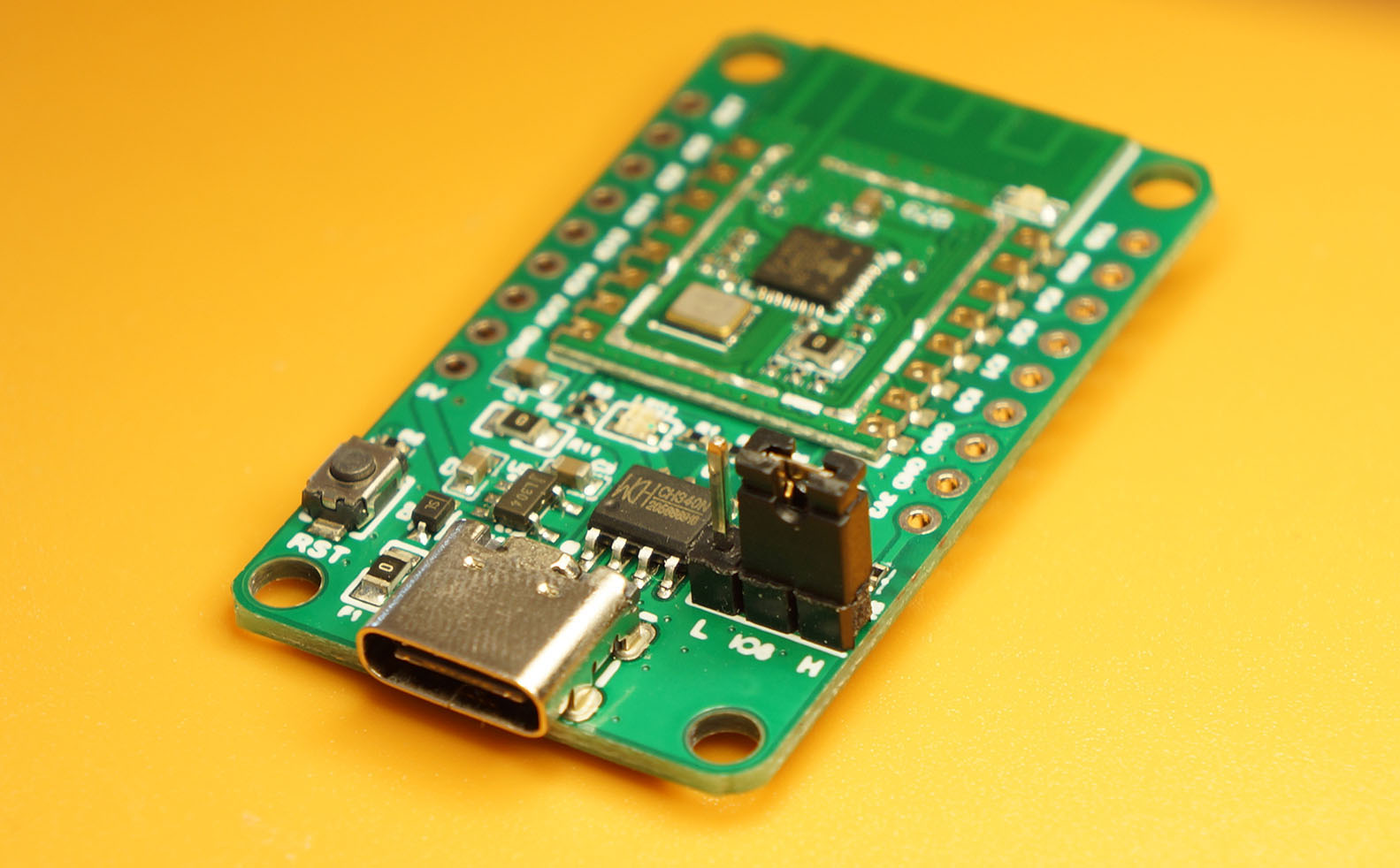
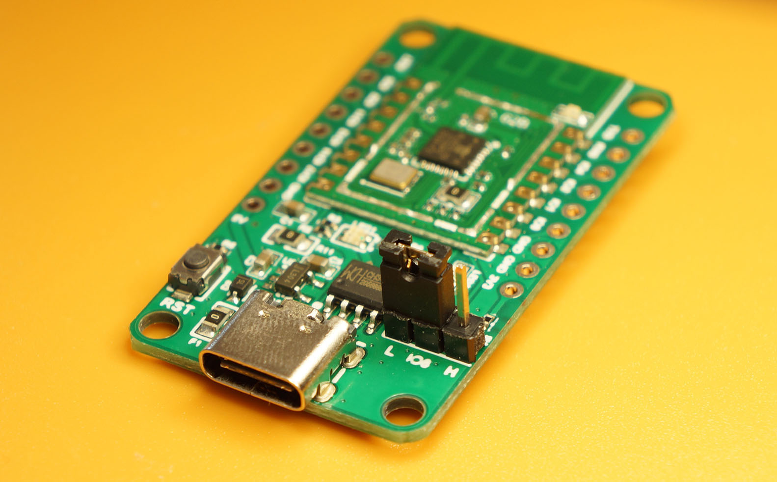
Set BL602 to Flashing Mode and restart the board.
For PineCone:
Set the PineCone Jumper (IO 8) to the H Position (Like this)
Press the Reset Button
For BL10:
Connect BL10 to the USB port
Press and hold the D8 Button (GPIO 8)
Press and release the EN Button (Reset)
Release the D8 Button
For Ai-Thinker Ai-WB2, Pinenut and MagicHome BL602:
Disconnect the board from the USB Port
Connect GPIO 8 to 3.3V
Reconnect the board to the USB port
Enter these commands to flash sdk_app_i2c.bin to BL602 over UART…
## For Linux:
blflash flash build_out/sdk_app_i2c.bin \
    --port /dev/ttyUSB0

## For macOS:
blflash flash build_out/sdk_app_i2c.bin \
    --port /dev/tty.usbserial-1420 \
    --initial-baud-rate 230400 \
    --baud-rate 230400

## For Windows: Change COM5 to the BL602 Serial Port
blflash flash c:\blflash\sdk_app_i2c.bin --port COM5
(For WSL: Do this under plain old Windows CMD, not WSL, because blflash needs to access the COM port)
More details on flashing firmware
Set BL602 to Normal Mode (Non-Flashing) and restart the board…
For PineCone:
Set the PineCone Jumper (IO 8) to the L Position (Like this)
Press the Reset Button
For BL10:
For Ai-Thinker Ai-WB2, Pinenut and MagicHome BL602:
Disconnect the board from the USB Port
Connect GPIO 8 to GND
Reconnect the board to the USB port
After restarting, connect to BL602’s UART Port at 2 Mbps like so…
For Linux:
screen /dev/ttyUSB0 2000000For macOS: Use CoolTerm (See this)
For Windows: Use putty (See this)
Alternatively: Use the Web Serial Terminal (See this)
More details on connecting to BL602
Let’s enter some I2C commands to read our BME280 Sensor!
Press Enter to reveal the command prompt.
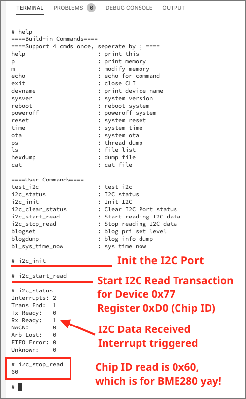
Enter help to see the available commands…
help
====User Commands====
i2c_status               : I2C status
i2c_init                 : Init I2C port
i2c_start_read           : Start reading I2C data
i2c_stop_read            : Stop reading I2C data
First we initialise our I2C Port.
Enter this command…
i2c_init(Earlier we’ve seen the code for this command)
Before doing any I2C business, let’s dump the Interrupt Counters to see which I2C Interrupts get triggered…
i2c_statusWe should see…
Interrupts: 0  NACK:       0
Trans End:  0  Arb Lost:   0
Tx Ready:   0  FIFO Error: 0
Rx Ready:   0  Unknown:    0
Which means that no I2C Interrupts have been triggered yet.
Now we start the I2C Read Operation…
i2c_start_read(We’ve seen the code for this command as well)
Again we dump the Interrupt Counters…
i2c_statusAha Something Different! We have encountered one interrupt for Data Received (Rx Ready), because BME280 has returned some I2C data to BL602…
Interrupts: 2  NACK:       0
Trans End:  1  Arb Lost:   0
Tx Ready:   0  FIFO Error: 0
Rx Ready:   1  Unknown:    0
After receiving the data (one byte) from BME280 (and saving it), our Interrupt Handler terminates the I2C connection.
Hence we see one interrupt for Transaction End. We’re done!
To check the data received, enter this command…
i2c_stop_readRemember that we’re reading the Chip ID from BME280. We should see this Chip ID…
60(For BMP280 the Chip ID is 0x58)
Congratulations! We have successfully read the BME280 Sensor from BL602 over I2C!
We have 2 problems when calling the Low Level I2C HAL…
Our program doesn’t wait for I2C Read/Write Operations to complete.
If we enter the command i2c_stop_read really quickly, it might terminate the I2C Read Operation before it’s done!
(Assuming we can type at superhuman speed)
The I2C data transfer happens in the background, executed by the Interrupt Handler. The Foreground Task isn’t notified when the data transfer is complete.
Solution: Our Interrupt Handler should use a Semaphore or a Message Queue to notify the Foreground Task when the data transfer is done.
Our program uses shared variables for I2C Read/Write Operations.
Remember these?
static i2c_msg_t *gpstmsg;    //  Global pointer to current I2C Message
static i2c_msg_t read_msg;    //  Message for reading I2C Data
static uint8_t read_buf[32];  //  Buffer for reading I2C Data
These global variables will get really confused when we talk to multiple I2C Sensors.
In fact, the entire I2C Port is a shared resource! It needs to be protected from overlapping I2C Operations.
Solution: Our program should use a Semaphore or a Mutex Lock to prevent concurrent updates to the shared variables.
We could use a Message Queue to enqueue I2C Requests and execute the I2C Requests one at a time.
What happens when we implement the two Solutions in FreeRTOS?
When we implement these two Solutions in FreeRTOS… We’ll get the High Level I2C HAL! (See hal_i2c.c)
Hence the High Level I2C HAL (which calls FreeRTOS) is fully functional today for processing I2C Sensor Data.
But the High Level I2C HAL lacks documentation… How do we use it?
The code explained in this article looks highly similar to the High Level I2C HAL.
Here’s the list of functions we’ve seen in this article, and their equivalent functions in the High Level I2C HAL…
| Function In This Article | Function In High Level HAL |
|---|---|
test_i2c_init | hal_i2c_init |
test_i2c_start_read | hal_i2c_read_block |
test_i2c_interrupt_entry | i2c_interrupt_entry |
test_i2c_transferbytes | i2c_transferbytes |
test_i2c_stop | i2c_callback |
Instead of FreeRTOS… Can we implement the two Solutions with Mynewt, RIOT or Zephyr?
Yes! We may implement the two Solutions with any Embedded Operating System that supports Task Synchronisation features (Semaphore, Mutex, Message Queue).
Thus to do meaningful work with I2C (like reading I2C Sensor Data periodically and processing the data), we need to use the Low Level I2C HAL together with an Embedded Operating System.
The High Level I2C HAL is a great reference that guides us on the proper implementation of the two Solutions on any operating system.
Hacking BL602 and BME280 on a Saturday Night
Now that we understand the inner workings of I2C on BL602…
Let’s port BL602 I2C to Mynewt and complete the I2C implementation…
Also work on BL602 SPI! Check out the article…
“PineCone BL602 talks SPI too”
(I have received ST7789 SPI displays for testing… Many thanks to my Generous Sponsor! 😀)
There’s plenty more code in the BL602 IoT SDK to be deciphered and documented: ADC, DAC, WiFi, Bluetooth LE, …
Come Join Us… Make BL602 Better!
🙏 👍 😀
Got a question, comment or suggestion? Create an Issue or submit a Pull Request here…
Check out the BL602 I2C HAL for Arduino
Why is BL602’s I2C Register Address feature incompatible with Mynewt (and other embedded operating systems)?
Because Mynewt exposes an I2C API that controls the I2C Stop Bit explicitly. (See this last_op parameter)
When porting BL602 I2C to Mynewt, we need to reconcile the two styles of I2C coding: Register Address vs Stop Bit.
We talked about reading I2C Registers… What about writing to I2C Registers?
The code should be similar. The demo program contains code for writing to I2C Registers, but it hasn’t been tested. And it needs cleaning up. See this
Why aren’t we using DMA for I2C?
DMA for I2C (and SPI) sounds overkill for an IoT Gadget. We should keep the firmware simple and easy to maintain. (Until we have more maintainers)
We’ll come back later to implement DMA for I2C (and SPI) if we need to do any high-speed bulk data transfer.
BL602 SPI doesn’t have a Low Level HAL… It only comes as a High Level HAL with FreeRTOS. Which will be a challenging exploration. See this
This article is the expanded version of this Twitter Thread
Quiz for the Reader: What could go wrong with this code?
(From Low Level I2C HAL bl_i2c.c)
Another Quiz for the Reader: Why does this code look dubious?
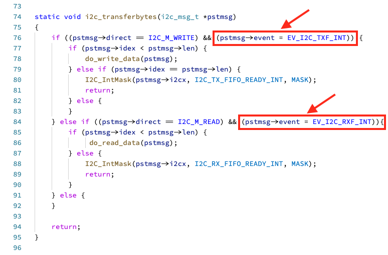
(From High Level I2C HAL hal_i2c.c)
Here’s how I tracked down my first RISC-V Exception and fixed it…
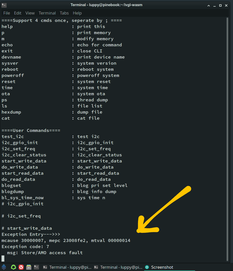
When our program sdk_app_i2c is sending I2C data, the program crashes with the RISC-V Exception shown above…
start_write_data
Exception Entry--->>>
mcause 30000007, mepc 23008fe2, mtval 00000014
Exception code: 7
msg: Store/AMO access fault
What does this mean?
mcause (Machine Cause Register): Tells us the reason for the exception. More details
The Exception Code is 7 (Store/AMO Access Fault), which means that we have accessed an invalid memory address.
(Probably a bad pointer)
mepc (Machine Exception Program Counter): The address of the code that caused the exception. More details
We’ll look up the code address 0x2300 8fe2 in a while.
mtval (Machine Trap Value Register): The invalid address that was accessed. More details
Our program attempted to access the invalid address 0x000 00014 and crashed.
Looks like a null pointer problem!
Let’s track down code address 0x2300 8fe2 and find out why it caused the exception…
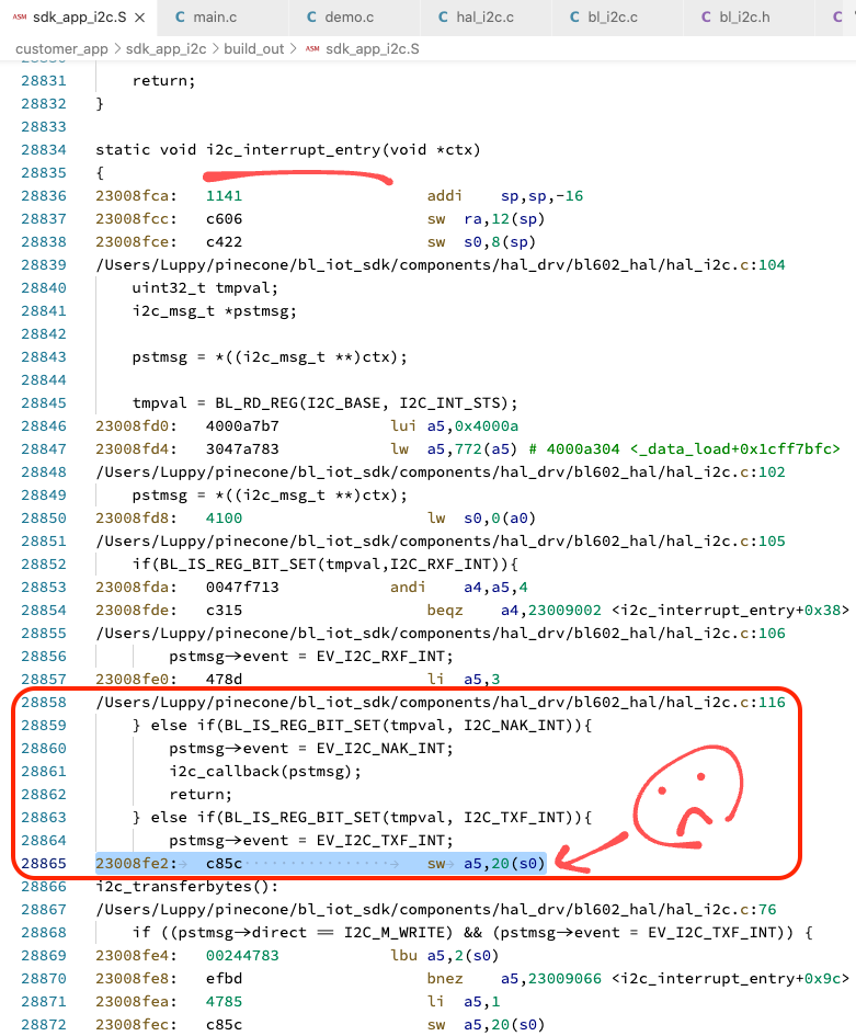
According to the RISC-V Disassembly sdk_app_i2c.S, the code address 0x2300 8fe2 is located in the I2C Interrupt Handler of the BL602 I2C HAL (See pic)
Why did it crash? Because the Interrupt Context ctx is null!
In fact, the I2C Interrupt Handler i2c_interrupt_entry shouldn’t have been called.
It comes from the High Level HAL hal_i2c.c, but we’re actually using the Low Level HAL bl_i2c.c.
Why was i2c_interrupt_entry set as the I2C Interrupt Handler?
Because hal_i2c_init was called here…
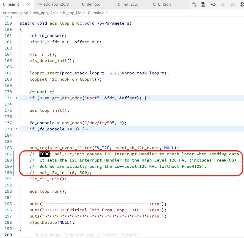
After commenting out hal_i2c_init, the program no longer uses i2c_interrupt_entry as the I2C Interrupt Handler.
And no more crashing!
For more RISC-V Exception troubleshooting tips, check out BL602 Stack Trace and BL602 Stack Dump…
How did we get the RISC-V Disassembly?
We generate RISC-V Disassembly sdk_app_i2c.S from ELF Executable sdk_app_i2c.elf with this command…
riscv-none-embed-objdump \
    -t -S --demangle --line-numbers --wide \
    sdk_app_i2c.elf \
    >sdk_app_i2c.S \
    2>&1
Is it safe to comment out hal_i2c_init?
Not quite. When we comment out hal_i2c_init, we disable the High Level I2C HAL functions in our demo firmware sdk_app_i2c
That’s the reason why we haven’t merged the i2c branch to the master branch…
i2c Branch is used for testing Low Level I2C HAL
master Branch is used for testing High Level I2C HAL
(The proper fix is to create a new command that calls hal_i2c_init)
What are the aos functions in the code above?
The aos functions are defined in AliOS. Remember that the High Level I2C HAL is called by AliOS Firmware.

Bus Pirate is a useful gadget for verifying whether our BME280 Sensor works OK. And for checking the I2C bytes that should be sent down the wire to BME280.
(Bus Pirate also works as a simple Protocol Analyser for sniffing I2C data)
Here’s how we test BME280 (or BMP280) with Bus Pirate…
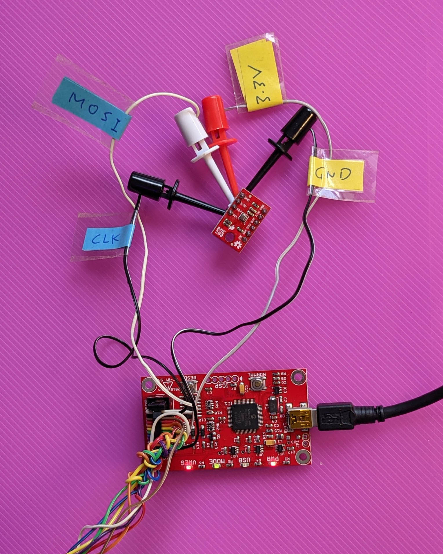
Connect Bus Pirate to BME280 (or BMP280) according to the pic above…
| Bus Pirate Pin | BME280 Pin |
|---|---|
MOSI | SDA |
CLK | SCL |
3.3V | 3.3V |
GND | GND |
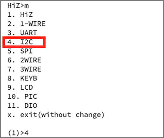
Connect Bus Pirate to our computer’s USB port.
Open a Serial Terminal for Bus Pirate.
Enter m for the menu
Select I2C
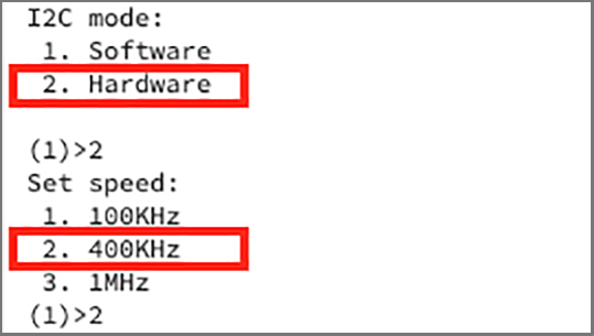
Select Hardware
Select 400 kbps
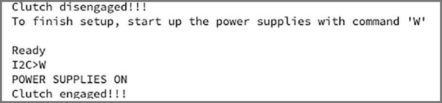
Enter W to power up BME280
Enter (1) to scan the I2C Bus
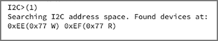
Here we see that BME280 has been detected at I2C Address 0x77
I2C uses the even / odd address convention to indicate whether we’re writing or reading data. So our BME280 at address 0x77 appears as two Read / Write aliases…
0xEE = (0x77 * 2) + 0, for Writing Data
0xEF = (0x77 * 2) + 1, for Reading Data
To read Register 0xD0 (Chip ID) from BME280, enter this command…
[0xee 0xd0] [0xef r](More about this later)
We should see the result 0x60, which is the Chip ID for BME280
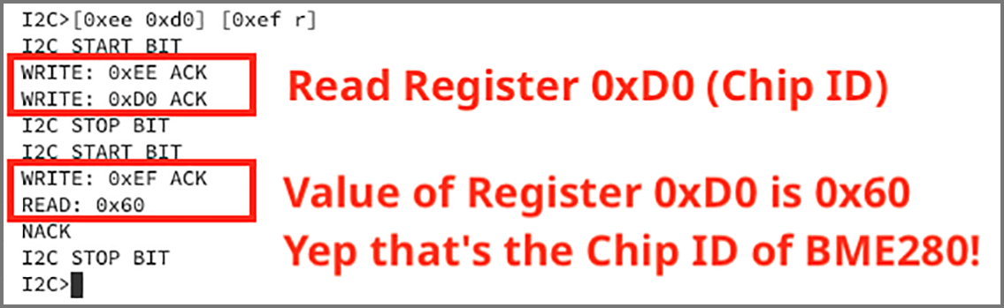
(For BMP280 the Chip ID is 0x58)
We tested BME280 with this Bus Pirate I2C command…
[0xee 0xd0] [0xef r]This means that Bus Pirate will initiate two I2C Transactions, indicated by [ ... ]
In the First I2C Transaction: Bus Pirate sends 0xEE to indicate a Write Transaction (for address 0x77).
Then it sends the I2C Register to be read: 0xD0 (Chip ID)
In the Second I2C Transaction: Bus Pirate sends 0xEF to indicate a Read Transaction (for address 0x77).
BME280 returns the value of the Chip ID Register, indicated by r
To sum up: Bus Pirate initiates two [ ... ] transactions. The transactions will send 3 bytes (0xEE, 0xD0, 0xEF) and receive 1 byte (0x60).
This is identical to the I2C data transmitted by BL602 to BME280 that have seen earlier in the article…
    [Start] 0xEE  0xD0  [Stop]

    [Start] 0xEF [Read] [Stop]
For help on other Bus Pirate commands, enter ?
Check out the I2C Guide for Bus Pirate
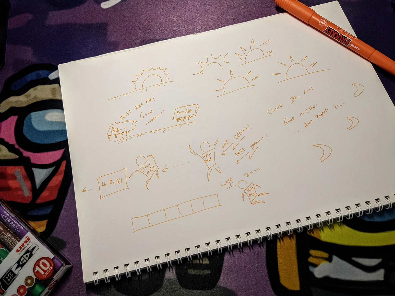
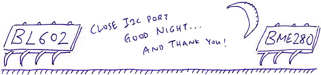
Sketching I2C cartoons. Download the Photoshop images