📝 28 Oct 2021
UPDATE: This PineDio USB driver is incomplete. Please use JF002/loramac-node instead
What if our Laptop Computer could talk to other devices…
Over a Long Range, Low Bandwidth wireless network like LoRa?
(Up to 5 km or 3 miles in urban areas… 15 km or 10 miles in rural areas!)
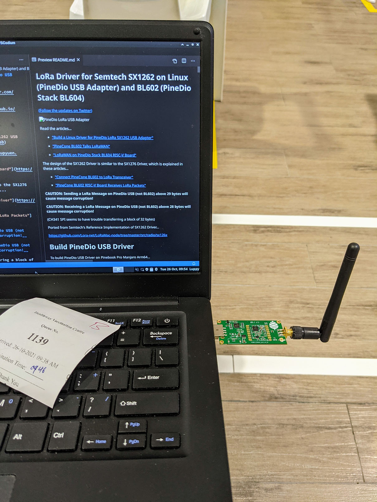
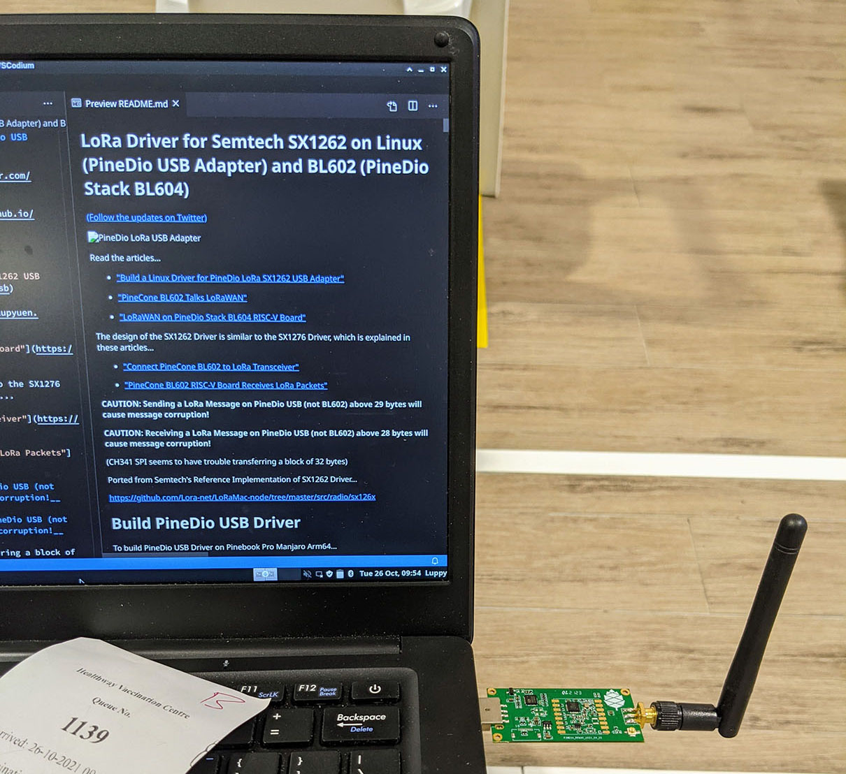
Yep that’s possible today… With Pinebook Pro and the PineDio LoRa SX1262 USB Adapter! (Pic below)
This article explains how we built the LoRa SX1262 Driver for PineDio USB Adapter and tested it on Pinebook Pro (Manjaro Linux Arm64)…
Our LoRa SX1262 Driver is still incomplete (it’s not a Kernel Driver yet), but the driver talks OK to other LoRa Devices. (With some limitations)
Read on to learn more…

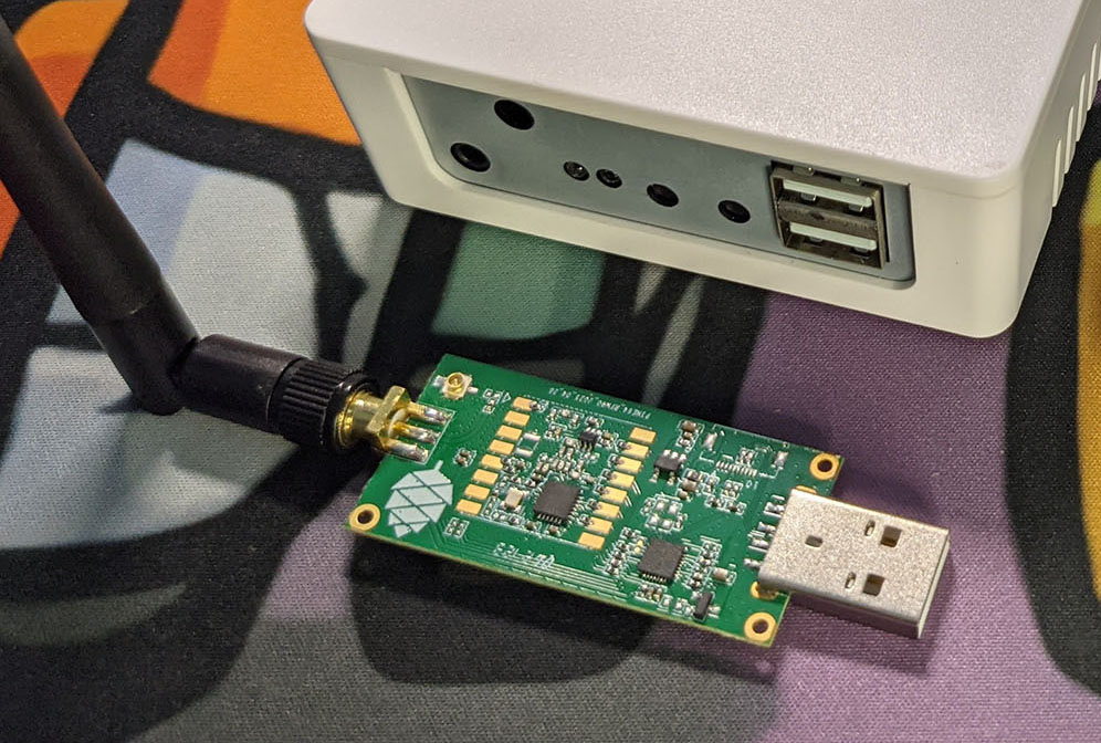
PineDio LoRa USB Adapter looks like a simple dongle…
Take a CH341 USB-to-Serial Interface Module
(Top half of pic below)
Connect it to a Semtech SX1262 LoRa Module over SPI
(Bottom half of pic below)
And we get the PineDio LoRa USB Adapter!
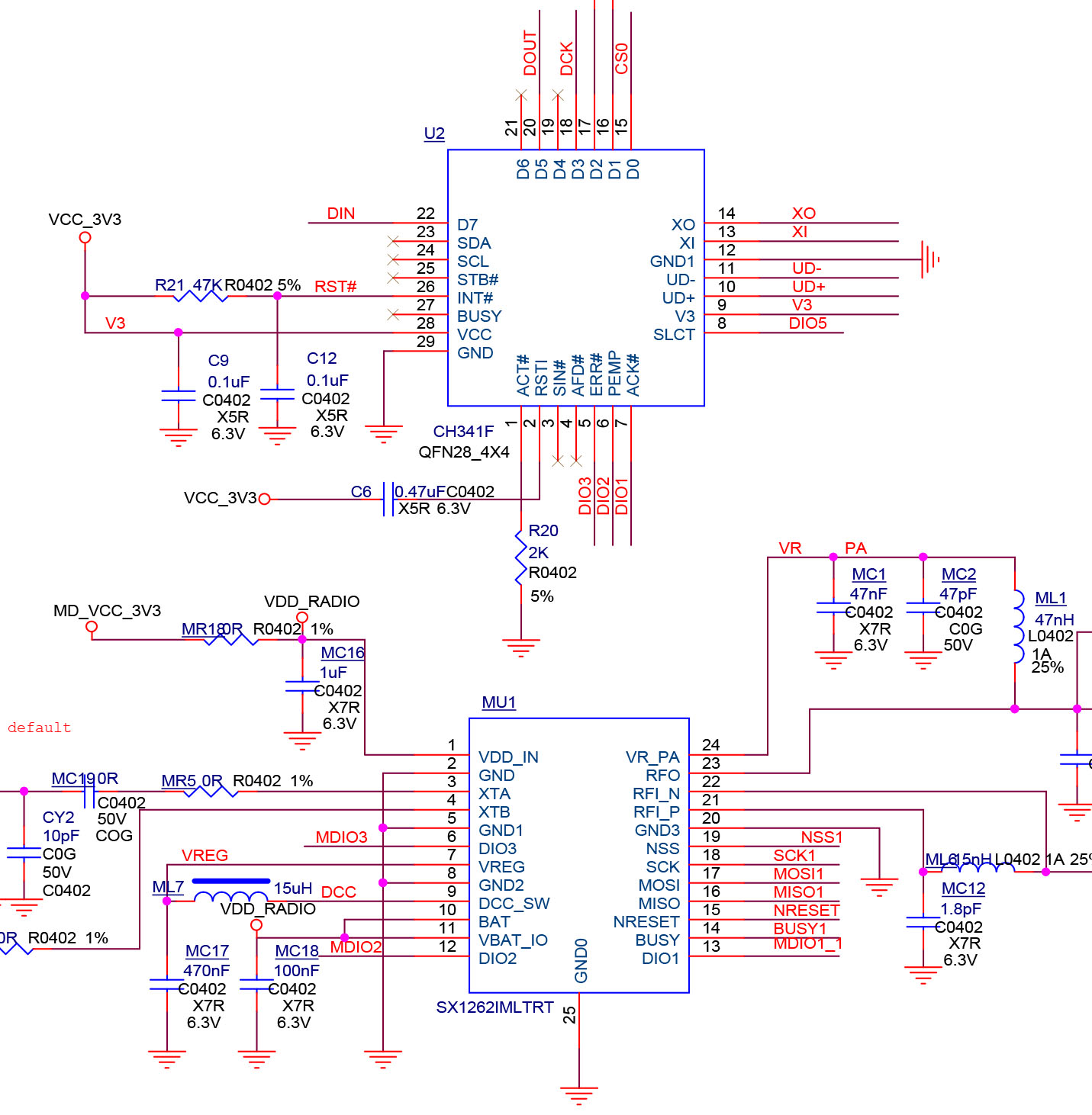
So CH341 exposes the SPI Interface for SX1262 over USB?
Yep Pinebook Pro shall control SX1262 over SPI, bridged by CH341.
Which means that we need to install a CH341 SPI Driver on Pinebook Pro.
(More about this in a while)
What about other pins on SX1262: DIO1, BUSY and NRESET?
DIO1 is used by SX1262 to signal that a LoRa Packet has been received.
BUSY is read by our computer to check if SX1262 is busy.
NRESET is toggled by our computer to reset the SX1262 module.
Pinebook Pro shall control these pins via the GPIO Interface on CH341, as we’ll see in a while.
Where did the PineDio USB LoRa Driver come from?
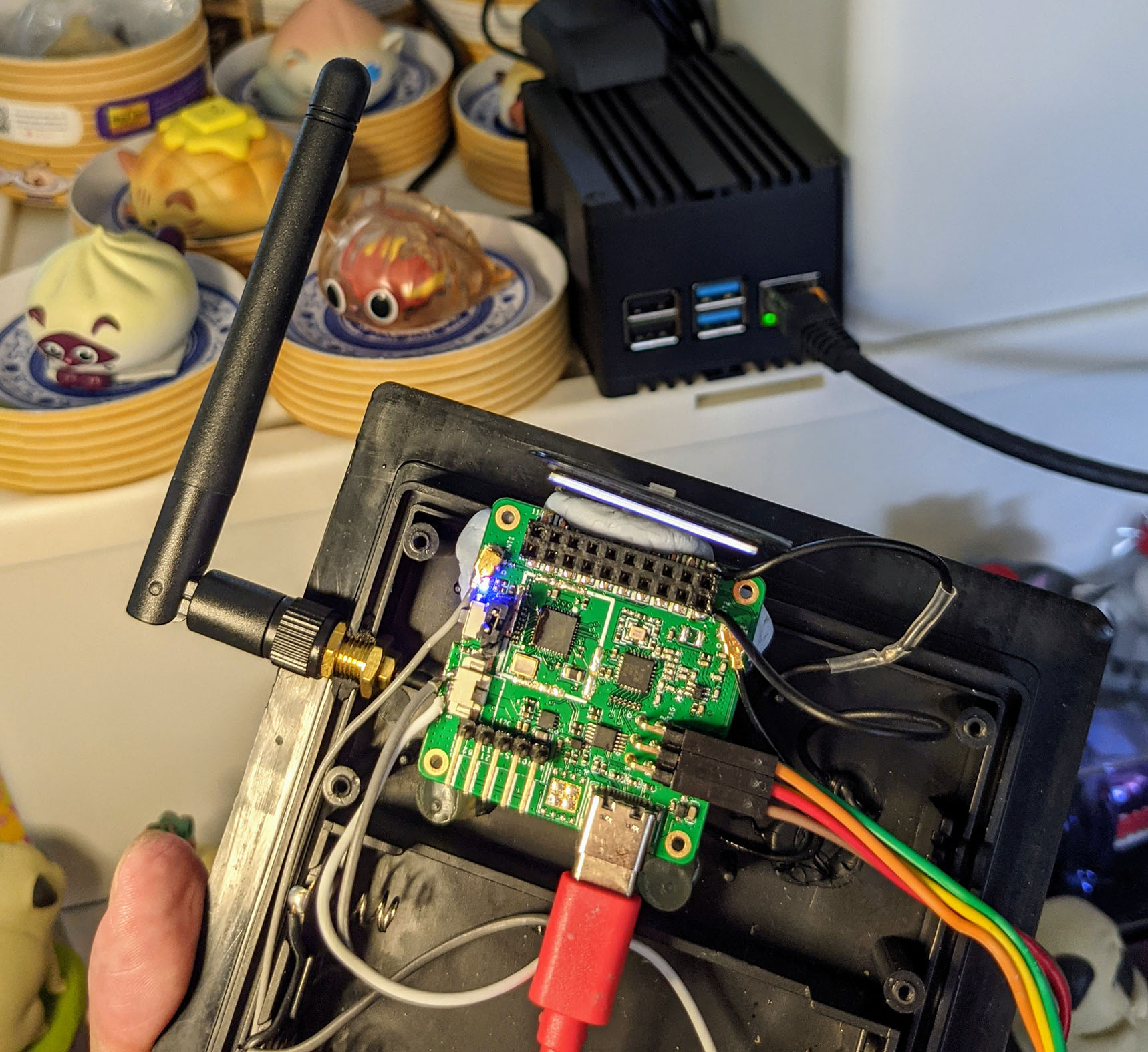
Believe it or not… The PineDio USB LoRa Driver is the exact same driver running on PineCone BL602 and PineDio Stack BL604! (Pic above)
But modified to talk to CH341 SPI for PineDio USB.
(And compiled for Arm64 instead of RISC-V 32-bit)
The BL602 / BL604 LoRa Driver was ported from Semtech’s Reference Implementation of SX1262 Driver…
There are many LoRa Drivers out there, why did we port Semtech’s Reference Driver?
That’s because Semtech’s Reference Driver supports LoRaWAN, which adds security features to low-level LoRa.
(Like for authentication and encryption)
How useful is LoRaWAN? Will we be using it?
Someday we might connect PineDio USB to a LoRaWAN Network like…
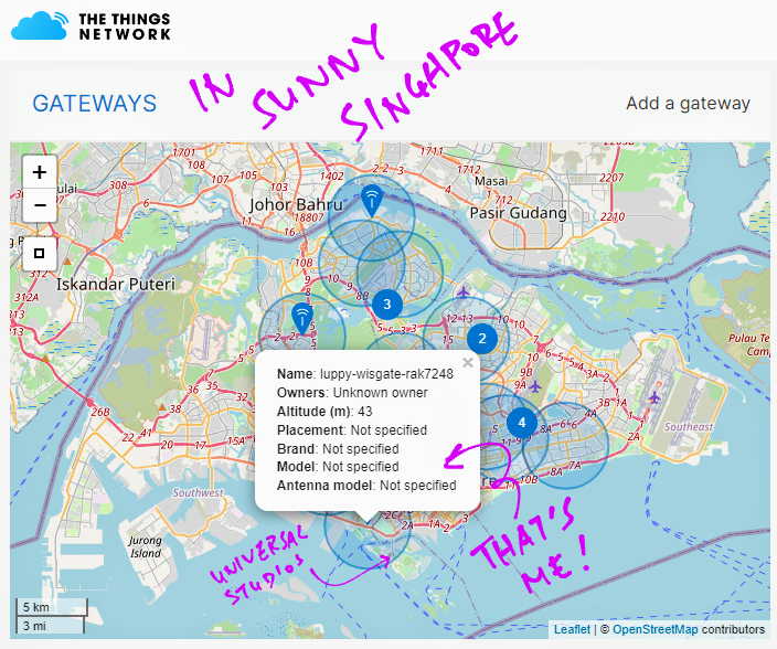
The Things Network: Free-to-use public global LoRaWAN Network for IoT devices. (Pic above)
Helium: Commercial global LoRaWAN Network for IoT devices.
Thus it’s good to build a LoRa Driver for PineDio USB that will support LoRaWAN in future.
(Seeking security on LoRa without LoRaWAN? Check out the LoRaWAN alternatives)
Do we call any open source libraries in our PineDio USB Driver?
Yes we call NimBLE Porting Layer, the open source library for Multithreading Functions…
To transmit and receive LoRa Messages we need Timers and Background Threads. Which are provided by NimBLE Porting Layer.
Have we used NimBLE Porting Layer before?
Yep we used NimBLE Porting Layer in the LoRa SX1262 and SX1276 Drivers for BL602…
So we’re really fortunate that NimBLE Porting Layer complies on Arm64 Linux as well.
(It’s part of PineTime InfiniTime too!)
What’s the simplest way to test our USB PineDio Driver?
To test whether our USB PineDio Driver is working with CH341 SPI, we can read the LoRa SX1262 Registers.
Here’s how: main.c
/// Main Function
int main(void) {
  //  Read SX1262 registers 0x00 to 0x0F
  read_registers();
  return 0;
}

/// Read SX1262 registers
static void read_registers(void) {
  //  Init the SPI port
  SX126xIoInit();

  //  Read and print the first 16 registers: 0 to 15
  for (uint16_t addr = 0; addr < 0x10; addr++) {
    //  Read the register
    uint8_t val = SX126xReadRegister(addr);

    //  Print the register value
    printf("Register 0x%02x = 0x%02x\r\n", addr, val);
  }
}(SX126xIoInit is defined here)
In our Main Function we call read_registers and SX126xReadRegister to read a bunch of SX1262 Registers. (0x00 to 0x0F)
In our PineDio USB Driver, SX126xReadRegister calls SX126xReadRegisters and sx126x_read_register to read each register: sx126x-linux.c
/// Read an SX1262 Register at the specified address
uint8_t SX126xReadRegister(uint16_t address) {
  //  Read one register and return the value
  uint8_t data;
  SX126xReadRegisters(address, &data, 1);
  return data;
}

/// Read one or more SX1262 Registers at the specified address.
/// `size` is the number of registers to read.
void SX126xReadRegisters(uint16_t address, uint8_t *buffer, uint16_t size) {
  //  Wake up SX1262 if sleeping
  SX126xCheckDeviceReady();

  //  Read the SX1262 registers
  int rc = sx126x_read_register(NULL, address, buffer, size);
  assert(rc == 0);

  //  Wait for SX1262 to be ready
  SX126xWaitOnBusy();
}
(We’ll see SX126xCheckDeviceReady and SX126xWaitOnBusy in a while)
sx126x_read_register reads a register by sending the Read Register Command to SX1262 over SPI: sx126x-linux.c
/// Send a Read Register Command to SX1262 over SPI
/// and return the results in `buffer`. `size` is the
/// number of registers to read.
static int sx126x_read_register(const void* context, const uint16_t address, uint8_t* buffer, const uint8_t size) {
  //  Reserve 4 bytes for our SX1262 Command Buffer
  uint8_t buf[SX126X_SIZE_READ_REGISTER] = { 0 };

  //  Init the SX1262 Command Buffer
  buf[0] = RADIO_READ_REGISTER;       //  Command ID
  buf[1] = (uint8_t) (address >> 8);  //  MSB of Register ID
  buf[2] = (uint8_t) (address >> 0);  //  LSB of Register ID
  buf[3] = 0;                         //  Unused

  //  Transmit the Command Buffer over SPI
  //  and receive the Result Buffer
  int status = sx126x_hal_read(
    context,  //  Context (unsued)
    buf,      //  Command Buffer
    SX126X_SIZE_READ_REGISTER,  //  Command Buffer Size: 4 bytes
    buffer,   //  Result Buffer
    size,     //  Result Buffer Size
    NULL      //  Status not required
  );
  return status;
}
And the values of the registers are returned by SX1262 over SPI.
(More about sx126x_hal_read later)
Follow the instructions to install the CH341 SPI Driver…
Follow the instructions to download, build and run the PineDio USB Driver…
Remember to edit src/main.c and uncomment…
#define READ_REGISTERSBuild and run the PineDio USB Driver…
## Build PineDio USB Driver
make

## Run PineDio USB Driver
sudo ./lora-sx1262
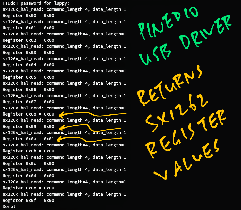
And watch for these SX1262 Register Values…
Register 0x00 = 0x00
...
Register 0x08 = 0x80
Register 0x09 = 0x00
Register 0x0a = 0x01If we see these values… Our PineDio USB Driver is talking correctly to CH341 SPI and SX1262!
Note that the values above will change when we transmit and receive LoRa Messages.
Let’s do that next.
We’re seeing layers of code, like an onion? (Or Shrek)
Yep we have layers of Source Files in our SX1262 Driver…
Source Files specific to Linux
(For PineDio USB and Pinebook Pro)
Source Files specific to BL602 and BL604
(For PineCone BL602 and PineDio Stack BL604)
Source Files common to all platforms
(For Linux, BL602 and BL604)
The Source Files specific to Linux are…
(Main Program for Linux)
(Linux Interface for SX1262 Driver)
(NimBLE Porting Layer for Linux)
All other Source Files are shared by Linux, BL602 and BL604.
(Except sx126x-board.c which is the BL602 / BL604 Interface for SX1262)
Before we transmit and receive LoRa Messages on PineDio USB, let’s talk about the LoRa Parameters.
To find out which LoRa Frequency we should use for our region…
We set the LoRa Frequency like so: main.c
/// TODO: We are using LoRa Frequency 923 MHz
/// for Singapore. Change this for your region.
#define USE_BAND_923
Change USE_BAND_923 to USE_BAND_433, 780, 868 or 915.
Below are the other LoRa Parameters: main.c
/// LoRa Parameters
#define LORAPING_TX_OUTPUT_POWER            14        /* dBm */

#define LORAPING_BANDWIDTH                  0         /* [0: 125 kHz, */
                                                      /*  1: 250 kHz, */
                                                      /*  2: 500 kHz, */
                                                      /*  3: Reserved] */
#define LORAPING_SPREADING_FACTOR           7         /* [SF7..SF12] */
#define LORAPING_CODINGRATE                 1         /* [1: 4/5, */
                                                      /*  2: 4/6, */
                                                      /*  3: 4/7, */
                                                      /*  4: 4/8] */
#define LORAPING_PREAMBLE_LENGTH            8         /* Same for Tx and Rx */
#define LORAPING_SYMBOL_TIMEOUT             5         /* Symbols */
#define LORAPING_FIX_LENGTH_PAYLOAD_ON      false
#define LORAPING_IQ_INVERSION_ON            false

#define LORAPING_TX_TIMEOUT_MS              3000    /* ms */
#define LORAPING_RX_TIMEOUT_MS              10000    /* ms */
#define LORAPING_BUFFER_SIZE 64 /* LoRa message size */During testing, these should match the LoRa Parameters used by the LoRa Transmitter / Receiver.
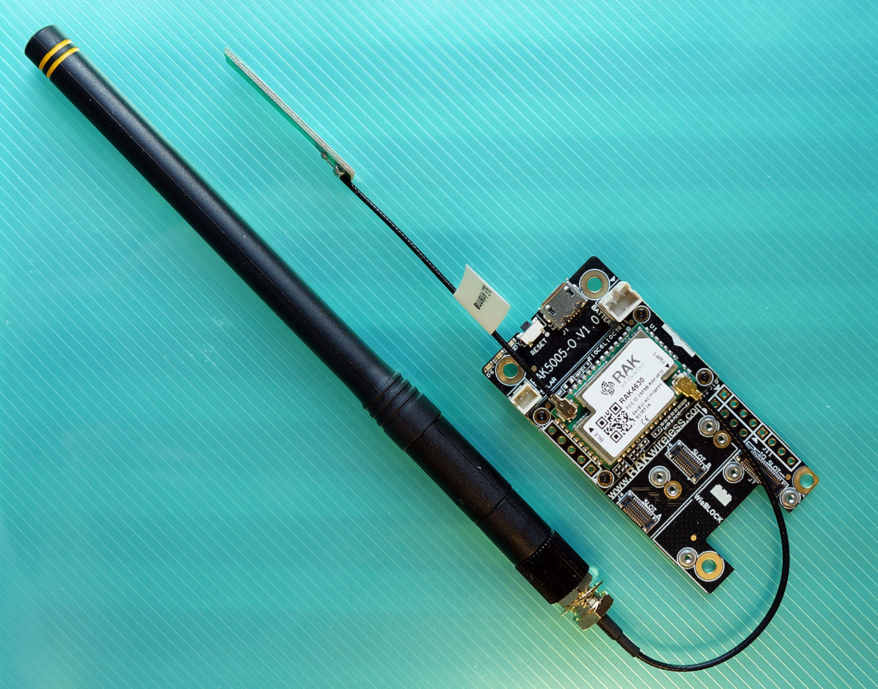
These are LoRa Transmitter and Receiver programs based on RAKwireless WisBlock (pic below) that I used for testing PineDio USB…
Thus the LoRa Parameters for PineDio USB should match the above.
Are there practical limits on the LoRa Parameters?
Yes we need to comply with the Local Regulations on the usage of ISM Radio Bands: FCC, ETSI, …
(Blasting LoRa Messages non-stop is no-no!)
When we connect PineDio USB to The Things Network, we need to comply with their Fair Use Policy…
Our init_driver function takes the above LoRa Parameters and initialises LoRa SX1262 like so: main.c
/// Command to initialise the LoRa Driver.
/// Assume that create_task has been called to init the Event Queue.
static void init_driver(char *buf, int len, int argc, char **argv) {
  //  Set the LoRa Callback Functions
  RadioEvents_t radio_events;
  memset(&radio_events, 0, sizeof(radio_events));  //  Must init radio_events to null, because radio_events lives on stack!
  radio_events.TxDone    = on_tx_done;     //  Packet has been transmitted
  radio_events.RxDone    = on_rx_done;     //  Packet has been received
  radio_events.TxTimeout = on_tx_timeout;  //  Transmit Timeout
  radio_events.RxTimeout = on_rx_timeout;  //  Receive Timeout
  radio_events.RxError   = on_rx_error;    //  Receive Error
Here we set the Callback Functions that will be called when a LoRa Message has been transmitted or received, also when we encounter a transmit / receive timeout or error.
(We’ll see the Callback Functions in a while)
Next we initialise the LoRa Transceiver and set the LoRa Frequency…
  //  Init the SPI Port and the LoRa Transceiver
  Radio.Init(&radio_events);

  //  Set the LoRa Frequency
  Radio.SetChannel(RF_FREQUENCY);
We set the LoRa Transmit Parameters…
  //  Configure the LoRa Transceiver for transmitting messages
  Radio.SetTxConfig(
    MODEM_LORA,
    LORAPING_TX_OUTPUT_POWER,
    0,        //  Frequency deviation: Unused with LoRa
    LORAPING_BANDWIDTH,
    LORAPING_SPREADING_FACTOR,
    LORAPING_CODINGRATE,
    LORAPING_PREAMBLE_LENGTH,
    LORAPING_FIX_LENGTH_PAYLOAD_ON,
    true,     //  CRC enabled
    0,        //  Frequency hopping disabled
    0,        //  Hop period: N/A
    LORAPING_IQ_INVERSION_ON,
    LORAPING_TX_TIMEOUT_MS
  );
Finally we set the LoRa Receive Parameters…
  //  Configure the LoRa Transceiver for receiving messages
  Radio.SetRxConfig(
    MODEM_LORA,
    LORAPING_BANDWIDTH,
    LORAPING_SPREADING_FACTOR,
    LORAPING_CODINGRATE,
    0,        //  AFC bandwidth: Unused with LoRa
    LORAPING_PREAMBLE_LENGTH,
    LORAPING_SYMBOL_TIMEOUT,
    LORAPING_FIX_LENGTH_PAYLOAD_ON,
    0,        //  Fixed payload length: N/A
    true,     //  CRC enabled
    0,        //  Frequency hopping disabled
    0,        //  Hop period: N/A
    LORAPING_IQ_INVERSION_ON,
    true      //  Continuous receive mode
  );
}
The Radio functions are Platform-Independent (Linux and BL602), defined in radio.c
RadioInit: Init LoRa SX1262
RadioSetChannel: Set LoRa Frequency
RadioSetTxConfig: Set LoRa Transmit Configuration
RadioSetRxConfig: Set LoRa Receive Configuration
(The Radio functions will also be called later when we implement LoRaWAN)
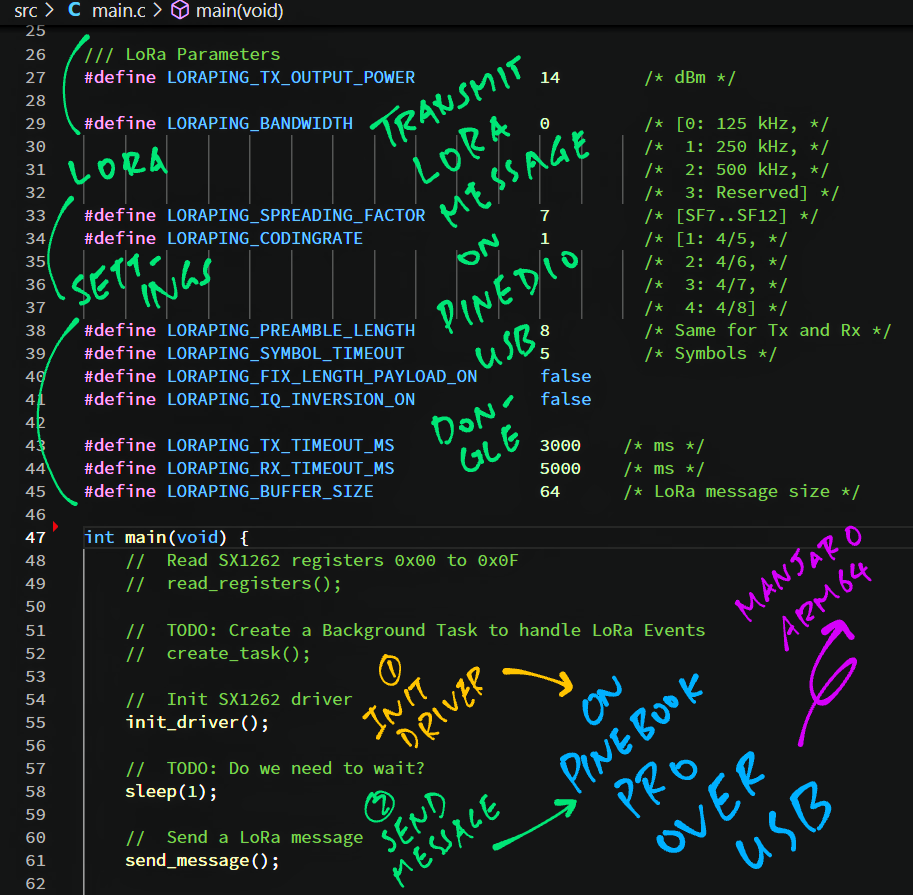
Now we’re ready to transmit a LoRa Message! Here’s how: main.c
/// Main Function
int main(void) {
  //  Init SX1262 driver
  init_driver();

  //  TODO: Do we need to wait?
  sleep(1);

  //  Send a LoRa message
  send_message();
  return 0;
}
We begin by calling init_driver to set the LoRa Parameters and the Callback Functions.
(We’ve seen init_driver in the previous section)
To transmit a LoRa Message, send_message calls send_once: main.c
/// Send a LoRa message. Assume that SX1262 driver has been initialised.
static void send_message(void) {
  //  Send the "PING" message
  send_once(1);
}
send_once prepares a 64-byte LoRa Message containing the string “PING”: demo.c
/// We send a "PING" message and expect a "PONG" response
const uint8_t loraping_ping_msg[] = "PING";
const uint8_t loraping_pong_msg[] = "PONG";

/// 64-byte buffer for our LoRa message
static uint8_t loraping_buffer[LORAPING_BUFFER_SIZE];

/// Send a LoRa message. If is_ping is 0, send "PONG". Otherwise send "PING".
static void send_once(int is_ping) {
  //  Copy the "PING" or "PONG" message
  //  to the transmit buffer
  if (is_ping) {
    memcpy(loraping_buffer, loraping_ping_msg, 4);
  } else {
    memcpy(loraping_buffer, loraping_pong_msg, 4);
  }
Then we pad the 64-byte message with values 0, 1, 2, …
  //  Fill up the remaining space in the
  //  transmit buffer (64 bytes) with values
  //  0, 1, 2, ...
  for (int i = 4; i < sizeof loraping_buffer; i++) {
    loraping_buffer[i] = i - 4;
  }
And we transmit the LoRa Message…
  //  We compute the message length, up to max 29 bytes.
  //  CAUTION: Anything more will cause message corruption!
  #define MAX_MESSAGE_SIZE 29
  uint8_t size = sizeof loraping_buffer > MAX_MESSAGE_SIZE
    ? MAX_MESSAGE_SIZE
    : sizeof loraping_buffer;

  //  We send the transmit buffer, limited to 29 bytes.
  //  CAUTION: Anything more will cause message corruption!
  Radio.Send(loraping_buffer, size);

  //  TODO: Previously we send 64 bytes, which gets garbled consistently.
  //  Does CH341 limit SPI transfers to 31 bytes?
  //  (Including 2 bytes for SX1262 SPI command header)
  //  Radio.Send(loraping_buffer, sizeof loraping_buffer);
}Our PineDio USB Driver has an issue with CH341 SPI Transfers…
Transmitting a LoRa Message on PineDio USB longer than 29 bytes will cause message corruption!
Thus we limit the Transmit LoRa Message Size to 29 bytes.
(There’s a way to fix this… More about CH341 later)
When the LoRa Message has been transmitted, the LoRa Driver calls our Callback Function on_tx_done defined in main.c
/// Callback Function that is called when our LoRa message has been transmitted
static void on_tx_done(void) {
  //  Log the success status
  loraping_stats.tx_success++;

  //  Switch the LoRa Transceiver to
  //  low power, sleep mode
  Radio.Sleep();
}(RadioSleep is explained here)
Here we log the number of packets transmitted, and put LoRa SX1262 into low power, sleep mode.
Note: on_tx_done won’t actually be called in our current driver, because we haven’t implemented Multithreading. (More about this later)
To handle Transmit Timeout Errors, we define the Callback Function on_tx_timeout: main.c
/// Callback Function that is called when our LoRa message couldn't be transmitted due to timeout
static void on_tx_timeout(void) {
  //  Switch the LoRa Transceiver to
  //  low power, sleep mode
  Radio.Sleep();

  //  Log the timeout
  loraping_stats.tx_timeout++;
}Follow the instructions to install the CH341 SPI Driver…
Follow the instructions to download, build and run the PineDio USB Driver…
Remember to edit src/main.c and uncomment…
#define SEND_MESSAGEAlso edit src/main.c and set the LoRa Parameters. (As explained earlier)
Build and run the PineDio USB Driver…
## Build PineDio USB Driver
make

## Run PineDio USB Driver
sudo ./lora-sx1262
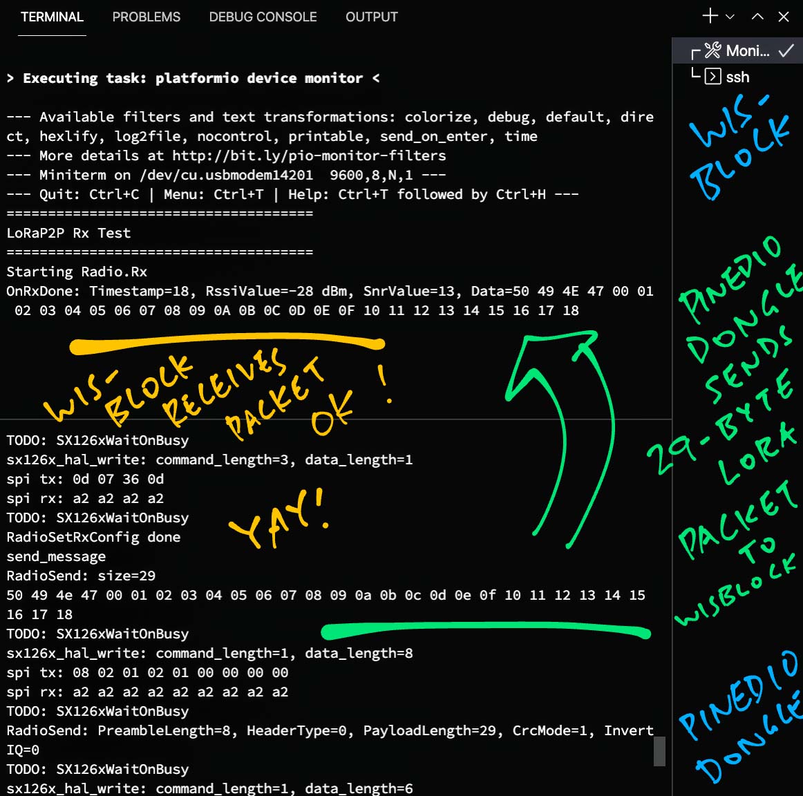
We should see PineDio USB transmitting our 29-byte LoRa Message…
send_message
RadioSend: size=29
50 49 4e 47 00 01 02 03 04 05 06 07 08 09 0a 0b 0c 0d 0e 0f 10 11 12 13 14 15 16 17 18 (“PING” followed by 0, 1, 2, …)
On RAKwireless WisBlock we should see the same 29-byte LoRa Message received…
LoRaP2P Rx Test
Starting Radio.Rx
OnRxDone: Timestamp=18, RssiValue=-28 dBm, SnrValue=13,
Data=50 49 4E 47 00 01 02 03 04 05 06 07 08 09 0A 0B 0C 0D 0E 0F 10 11 12 13 14 15 16 17 18 PineDio USB has successfully transmitted a 29-byte LoRa Message to RAKwireless WisBlock!
What if nothing appears in our LoRa Receiver?
Use a Spectrum Analyser (like a Software Defined Radio) to sniff the airwaves and check whether our LoRa Message is transmitted…
At the right Radio Frequency
(923 MHz below)
With sufficient power
(Red stripe below)
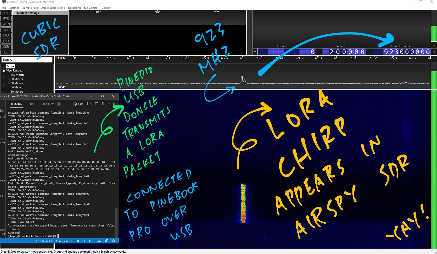
LoRa Messages have a characteristic criss-cross shape: LoRa Chirp. (Like above)
More about LoRa Chirps and Software Defined Radio…
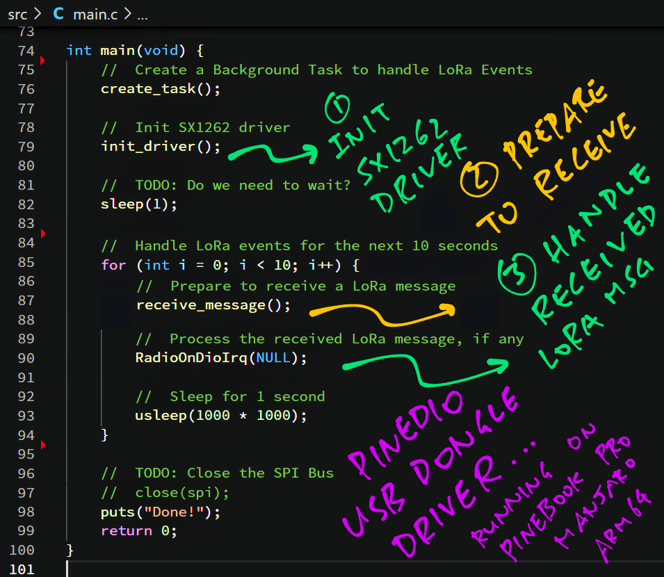
Let’s receive a LoRa Message on PineDio USB!
This is how we do it: main.c
/// Main Function
int main(void) {
  //  TODO: Create a Background Thread
  //  to handle LoRa Events
  create_task();
We start by creating a Background Thread to handle LoRa Events.
(create_task doesn’t do anything because we haven’t implemented Multithreading. More about this later)
Next we set the LoRa Parameters and the Callback Functions…
  //  Init SX1262 driver
  init_driver();

  //  TODO: Do we need to wait?
  sleep(1);
(Yep the same init_driver we’ve seen earlier)
For the next 10 seconds we poll and handle LoRa Events (like Message Received)…
  //  Handle LoRa events for the next 10 seconds
  for (int i = 0; i < 10; i++) {
    //  Prepare to receive a LoRa message
    receive_message();

    //  Process the received LoRa message, if any
    RadioOnDioIrq(NULL);

    //  Sleep for 1 second
    usleep(1000 * 1000);
  }
  return 0;
}
We call receive_message to get SX1262 ready to receive a single LoRa Message.
Then we call RadioOnDioIrq to handle the Message Received Event. (If any)
(RadioOnDioIrq is explained here)
receive_message is defined like so: main.c
/// Receive a LoRa message. Assume that SX1262 driver has been initialised.
/// Assume that create_task has been called to init the Event Queue.
static void receive_message(void) {
  //  Receive a LoRa message within the timeout period
  Radio.Rx(LORAPING_RX_TIMEOUT_MS);
}When the LoRa Driver receives a LoRa Message, it calls our Callback Function on_rx_done defined in main.c
/// Callback Function that is called when a LoRa message has been received
static void on_rx_done(
  uint8_t *payload,  //  Buffer containing received LoRa message
  uint16_t size,     //  Size of the LoRa message
  int16_t rssi,      //  Signal strength
  int8_t snr) {      //  Signal To Noise ratio

  //  Switch the LoRa Transceiver to low power, sleep mode
  Radio.Sleep();

  //  Log the signal strength, signal to noise ratio
  loraping_rxinfo_rxed(rssi, snr);
on_rx_done switches the LoRa Transceiver to low power, sleep mode and logs the received packet.
Next we copy the received packet into a buffer…
  //  Copy the received packet
  if (size > sizeof loraping_buffer) {
    size = sizeof loraping_buffer;
  }
  loraping_rx_size = size;
  memcpy(loraping_buffer, payload, size);
Finally we dump the buffer containing the received packet…
  //  Dump the contents of the received packet
  for (int i = 0; i < loraping_rx_size; i++) {
    printf("%02x ", loraping_buffer[i]);
  }
  printf("\r\n");
}
What happens when we don’t receive a packet in 10 seconds? (LORAPING_RX_TIMEOUT_MS)
The LoRa Driver calls our Callback Function on_rx_timeout defined in main.c
/// Callback Function that is called when no LoRa messages could be received due to timeout
static void on_rx_timeout(void) {
  //  Switch the LoRa Transceiver to low power, sleep mode
  Radio.Sleep();

  //  Log the timeout
  loraping_stats.rx_timeout++;
}
We switch the LoRa Transceiver into sleep mode and log the timeout.
Note: on_rx_timeout won’t actually be called in our current driver, because we haven’t implemented Multithreading. (More about this later)
To handle Receive Errors, we define the Callback Function on_rx_error: main.c
/// Callback Function that is called when we couldn't receive a LoRa message due to error
static void on_rx_error(void) {
  //  Log the error
  loraping_stats.rx_error++;

  //  Switch the LoRa Transceiver to low power, sleep mode
  Radio.Sleep();
}Follow the instructions to install the CH341 SPI Driver…
Follow the instructions to download, build and run the PineDio USB Driver…
Remember to edit src/main.c and uncomment…
#define RECEIVE_MESSAGEAlso edit src/main.c and set the LoRa Parameters. (As explained earlier)
Build and run the PineDio USB Driver…
## Build PineDio USB Driver
make

## Run PineDio USB Driver
sudo ./lora-sx1262
Switch over to RAKwireless WisBlock and transmit a 28-byte LoRa Message…
LoRap2p Tx Test
send: 48 65 6c 6c 6f 00 01 02 03 04 05 06 07 08 09 0a 0b 0c 0d 0e 0f 10 11 12 13 14 15 16
OnTxDone(“Hello” followed by 0, 1, 2, …)
On PineDio USB we should see the same 28-byte LoRa Message…
IRQ_RX_DONE
03 04 05 06 07 08 09 0a 0b 0c 0d 0e 0f 10 11 12 13 14 15 16 48 65 6c 6c 6f 00 01 02
IRQ_PREAMBLE_DETECTED
IRQ_HEADER_VALID
receive_messagePineDio USB has successfully received a 28-byte LoRa Message from RAKwireless WisBlock!
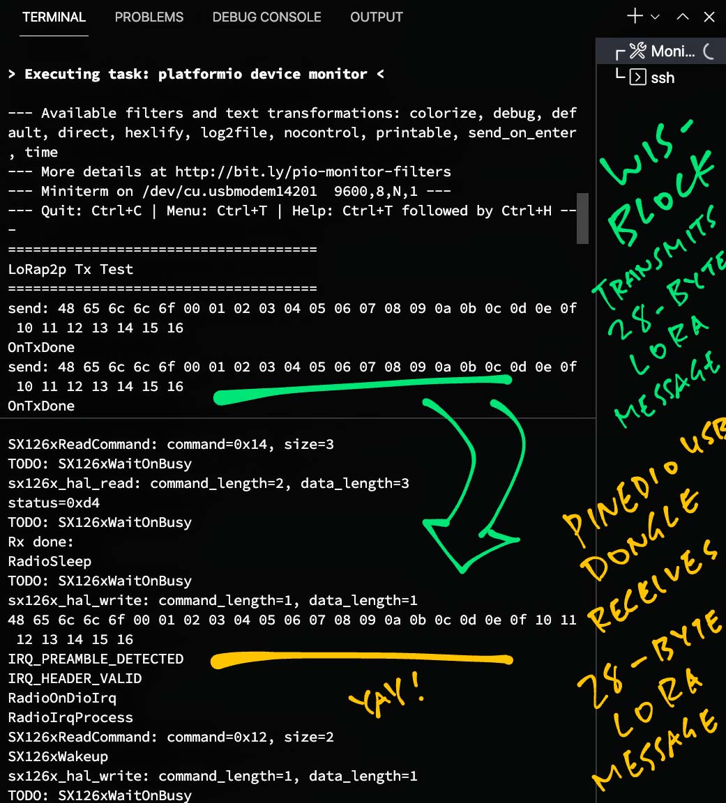
Why 28 bytes?
Our PineDio USB Driver has an issue with CH341 SPI Transfers…
Receiving a LoRa Message on PineDio USB longer than 28 bytes will cause message corruption!
Thus we limit the Receive LoRa Message Size to 28 bytes.
There’s a way to fix this… Coming up next!

Remember that PineDio USB Dongle contains a CH341 USB-to-Serial Interface Module that talks to LoRa SX1262 (over SPI)…
Pinebook Pro (Manjaro Linux Arm64) has a built-in driver for CH341… But it doesn’t support SPI.
Thus for our PineDio USB Driver we’re calling this CH341 SPI Driver…
We install the CH341 SPI Driver with these steps…
Now let’s call the CH341 SPI Driver from our PineDio USB Driver.
Here’s how our PineDio USB Driver calls CH341 SPI Driver to initialise the SPI Bus: sx126x-linux.c
/// SPI Bus
static int spi = 0;

/// Init the SPI Bus. Return 0 on success.
static int init_spi(void) {
  //  Open the SPI Bus
  spi = open("/dev/spidev1.0", O_RDWR);
  assert(spi > 0);

  //  Set to SPI Mode 0
  uint8_t mmode = SPI_MODE_0;
  int rc = ioctl(spi, SPI_IOC_WR_MODE, &mmode);
  assert(rc == 0);

  //  Set LSB/MSB Mode
  uint8_t lsb = 0;
  rc = ioctl(spi, SPI_IOC_WR_LSB_FIRST, &lsb);
  assert(rc == 0);
  return 0;
}
init_spi is called by SX126xIoInit, which is called by RadioInit and init_driver
(We’ve seen init_driver earlier)
To transfer SPI Data between PineDio USB and CH341 / SX1262, we do this: sx126x-linux.c
/// Blocking call to transmit and receive buffers on SPI. Return 0 on success.
static int transfer_spi(const uint8_t *tx_buf, uint8_t *rx_buf, uint16_t len) {
  assert(spi > 0);
  assert(len > 0);
  assert(len <= 31);  //  CAUTION: CH341 SPI doesn't seem to support 32-byte SPI transfers

  //  Prepare SPI Transfer
  struct spi_ioc_transfer spi_trans;
  memset(&spi_trans, 0, sizeof(spi_trans));
  spi_trans.tx_buf = (unsigned long) tx_buf;  //  Transmit Buffer
  spi_trans.rx_buf = (unsigned long) rx_buf;  //  Receive Buffer
  spi_trans.cs_change = true;   //  Set SPI Chip Select to Low
  spi_trans.len       = len;    //  How many bytes
  printf("spi tx: "); for (int i = 0; i < len; i++) { printf("%02x ", tx_buf[i]); } printf("\n");

  //  Transfer and receive the SPI buffers
  int rc = ioctl(spi, SPI_IOC_MESSAGE(1), &spi_trans);
  assert(rc >= 0);
  assert(rc == len);

  printf("spi rx: "); for (int i = 0; i < len; i++) { printf("%02x ", rx_buf[i]); } printf("\n");
  return 0;
}(transfer_spi will be called by our PineDio USB Driver, as we’ll see later)
transfer_spi has a strange assertion that stops large SPI transfers…
//  CAUTION: CH341 SPI doesn't seem to
//  support 32-byte SPI transfers
assert(len <= 31);
We’ll learn why in a while.
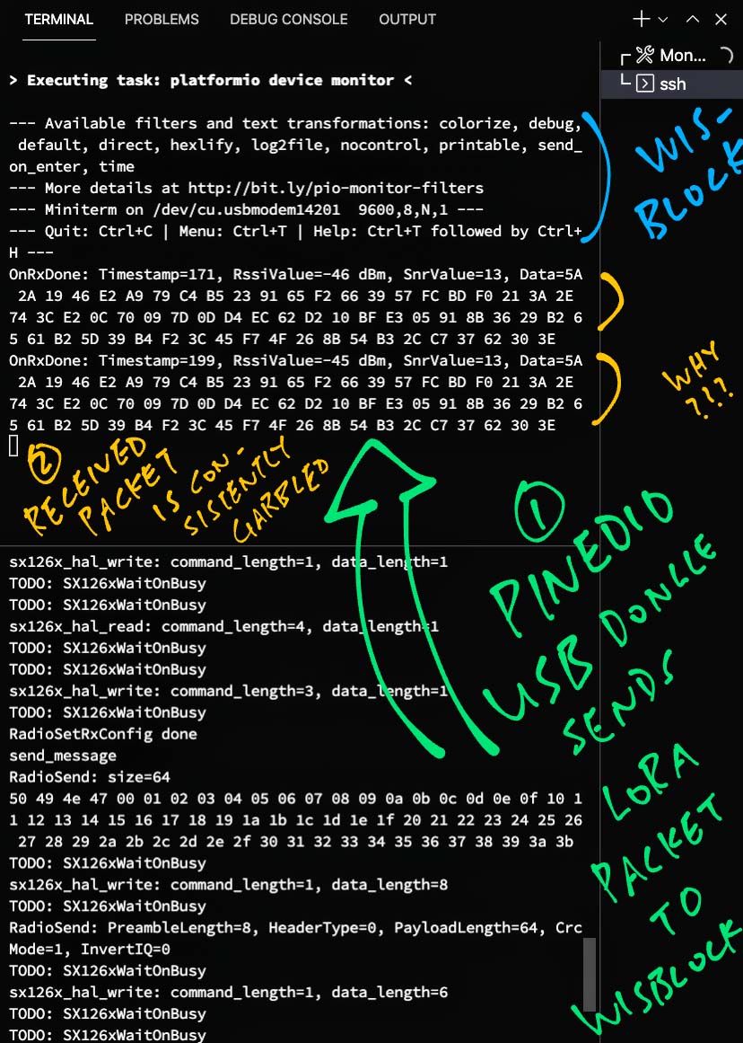
What happens when we transmit a LoRa Message longer than 29 bytes?
The pic above shows what happens when we transmit a long message (64 bytes) from PineDio USB to RAKwireless WisBlock…
Our 64-byte message is garbled when received
(By RAKwireless WisBlock)
But the message is consistently garbled
(RAKwireless WisBlock receives the same garbled message twice, not any random message)
Which means it’s not due to Radio Interference
(Radio Interference would garble the messages randomly)
By tweaking our PineDio USB Driver, we discover two shocking truths…
Transmitting a LoRa Message on PineDio USB longer than 29 bytes will cause message corruption!
Receiving a LoRa Message on PineDio USB longer than 28 bytes will cause message corruption!
Let’s trace the code and solve this mystery.
Our PineDio USB Driver calls this function to transmit a LoRa Message: sx126x-linux.c
static int sx126x_write_buffer(const void* context, const uint8_t offset, const uint8_t* buffer, const uint8_t size) {
  //  Prepare the Write Buffer Command (2 bytes)
  uint8_t buf[SX126X_SIZE_WRITE_BUFFER] = { 0 };
  buf[0] = RADIO_WRITE_BUFFER;  //  Write Buffer Command
  buf[1] = offset;              //  Write Buffer Offset

  //  Transfer the Write Buffer Command to SX1262 over SPI
  return sx126x_hal_write(
    context,  //  Context
    buf,      //  Command Buffer
    SX126X_SIZE_WRITE_BUFFER,  //  Command Buffer Size (2 bytes)
    buffer,   //  Write Data Buffer
    size      //  Write Data Buffer Size
  );
}
In this code we prepare a SX1262 Write Buffer Command (2 bytes) and pass the Command Buffer (plus Data Buffer) to sx126x_hal_write.
(Data Buffer contains the LoRa Message to be transmitted)
Note that Write Buffer Offset is always 0, because of SX126xSetPayload and SX126xWriteBuffer.
(SX126xSetPayload and SX126xWriteBuffer are explained here)
sx126x_hal_write transfers the Command Buffer and Data Buffer over SPI: sx126x-linux.c
/**
 * Radio data transfer - write
 *
 * @remark Shall be implemented by the user
 *
 * @param [in] context          Radio implementation parameters
 * @param [in] command          Pointer to the buffer to be transmitted
 * @param [in] command_length   Buffer size to be transmitted
 * @param [in] data             Pointer to the buffer to be transmitted
 * @param [in] data_length      Buffer size to be transmitted
 *
 * @returns Operation status
 */
static int sx126x_hal_write(
  const void* context, const uint8_t* command, const uint16_t command_length,
  const uint8_t* data, const uint16_t data_length ) {
  printf("sx126x_hal_write: command_length=%d, data_length=%d\n", command_length, data_length);

  //  Total length is command + data length
  uint16_t len = command_length + data_length;
  assert(len > 0);
  assert(len <= SPI_BUFFER_SIZE);

  //  Clear the SPI Transmit and Receive buffers
  memset(&spi_tx_buf, 0, len);
  memset(&spi_rx_buf, 0, len);

  //  Copy command bytes to SPI Transmit Buffer
  memcpy(&spi_tx_buf, command, command_length);

  //  Copy data bytes to SPI Transmit Buffer
  memcpy(&spi_tx_buf[command_length], data, data_length);

  //  Transmit and receive the SPI buffers
  int rc = transfer_spi(spi_tx_buf, spi_rx_buf, len);
  assert(rc == 0);
  return 0;
}
We use an internal 1024-byte buffer for SPI Transfers, so we’re hunky dory here: sx126x-linux.c
/// Max size of SPI transfers
#define SPI_BUFFER_SIZE 1024

/// SPI Transmit Buffer
static uint8_t spi_tx_buf[SPI_BUFFER_SIZE];

/// SPI Receive Buffer
static uint8_t spi_rx_buf[SPI_BUFFER_SIZE];
sx126x_hal_write calls transfer_spi to transfer the SPI Data.
(We’ve seen transfer_spi earlier)
Thus transfer_spi looks highly sus for transmitting Long LoRa Messages.
What about receiving Long LoRa Messages?
Our PineDio USB Driver calls this function to receive a LoRa Message: sx126x-linux.c
static int sx126x_read_buffer(const void* context, const uint8_t offset, uint8_t* buffer, const uint8_t size) {
  //  Prepare the Read Buffer Command (3 bytes)
  uint8_t buf[SX126X_SIZE_READ_BUFFER] = { 0 };
  buf[0] = RADIO_READ_BUFFER;  //  Read Buffer Command
  buf[1] = offset;             //  Read Buffer Offset
  buf[2] = 0;                  //  NOP

  //  Transfer the Read Buffer Command to SX1262 over SPI
  int status = sx126x_hal_read(
    context,  //  Context
    buf,      //  Command Buffer
    SX126X_SIZE_READ_BUFFER,  //  Command Buffer Size (3 bytes)
    buffer,   //  Read Data Buffer
    size,     //  Read Data Buffer Size
    NULL      //  Ignore the status
  );
  return status;
}
In this code we prepare a SX1262 Read Buffer Command (3 bytes) and pass the Command Buffer (plus Data Buffer) to sx126x_hal_read.
(Data Buffer will contain the received LoRa Message)
Note that Read Buffer Offset is always 0, because of SX126xGetPayload and SX126xReadBuffer.
(SX126xGetPayload and SX126xReadBuffer are explained here)
sx126x_hal_read transfers the Command Buffer over SPI: sx126x-linux.c
/**
 * Radio data transfer - read
 *
 * @remark Shall be implemented by the user
 *
 * @param [in] context          Radio implementation parameters
 * @param [in] command          Pointer to the buffer to be transmitted
 * @param [in] command_length   Buffer size to be transmitted
 * @param [in] data             Pointer to the buffer to be received
 * @param [in] data_length      Buffer size to be received
 * @param [out] status          If not null, return the second SPI byte received as status
 *
 * @returns Operation status
 */
static int sx126x_hal_read(
  const void* context, const uint8_t* command, const uint16_t command_length,
  uint8_t* data, const uint16_t data_length, uint8_t *status ) {
  printf("sx126x_hal_read: command_length=%d, data_length=%d\n", command_length, data_length);

  //  Total length is command + data length
  uint16_t len = command_length + data_length;
  assert(len > 0);
  assert(len <= SPI_BUFFER_SIZE);

  //  Clear the SPI Transmit and Receive buffers
  memset(&spi_tx_buf, 0, len);
  memset(&spi_rx_buf, 0, len);

  //  Copy command bytes to SPI Transmit Buffer
  memcpy(&spi_tx_buf, command, command_length);

  //  Transmit and receive the SPI buffers
  int rc = transfer_spi(spi_tx_buf, spi_rx_buf, len);
  assert(rc == 0);

  //  Copy SPI Receive buffer to data buffer
  memcpy(data, &spi_rx_buf[command_length], data_length);

  //  Return the second SPI byte received as status
  if (status != NULL) {
    assert(len >= 2);
    *status = spi_rx_buf[1];
  }
  return 0;
}
And returns the Data Buffer that has been read over SPI.
sx126x_hal_read also calls transfer_spi to transfer the SPI Data.
Now transfer_spi is doubly sus… The same function is called to transmit AND receive Long LoRa Messages!
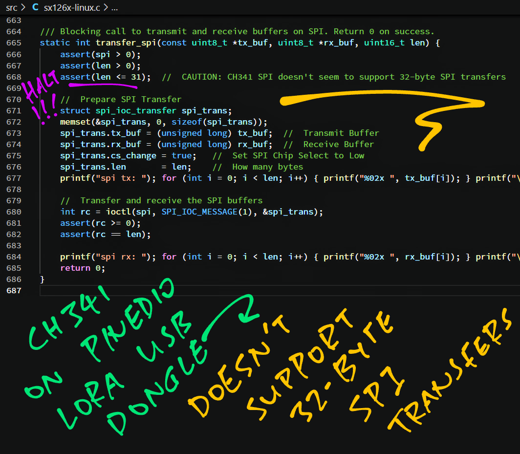
Does transfer_spi impose a limit on the size of SPI Transfers?
With some tweaking, we discover that transfer_spi garbles the data when transferring 32 bytes or more!
This seems to be a limitation of the CH341 SPI Driver.
(Due to CH341_USB_MAX_BULK_SIZE maybe?)
Hence we limit all SPI Transfers to 31 bytes: sx126x-linux.c
/// Blocking call to transmit and receive buffers on SPI. Return 0 on success.
static int transfer_spi(const uint8_t *tx_buf, uint8_t *rx_buf, uint16_t len) {
  //  CAUTION: CH341 SPI doesn't seem to
  //  support 32-byte SPI transfers
  assert(len <= 31);
Why 29 bytes for the max transmit size? And 28 bytes for the max receive size?
That’s because…
SX1262 Write Buffer Command (for transmit) occupies 2 SPI bytes
SX1262 Read Buffer Command (for receive) occupies 3 SPI bytes
But wait! We might have a fix for Long LoRa Messages…
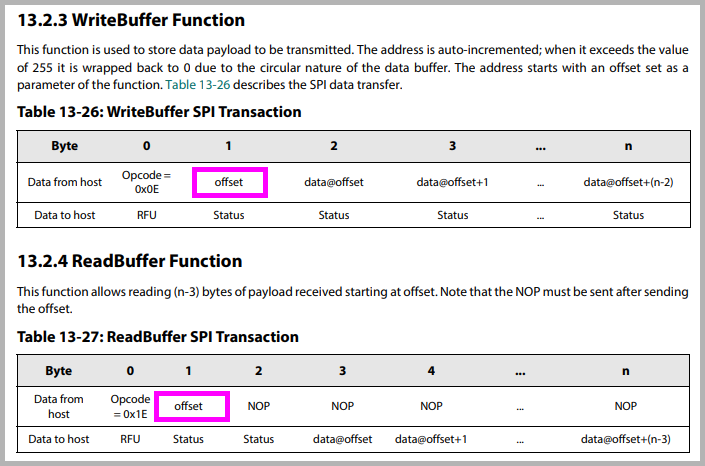
(From Semtech SX1262 Datasheet)
Is there a way to fix Long LoRa Messages on PineDio USB?
Let’s look back at our code in sx126x_write_buffer.
To transmit a LoRa Message, we send the WriteBuffer Command to SX1262 over SPI…
WriteBuffer Command: 0x0E
WriteBuffer Offset: 0x00
WriteBuffer Data: Transfer 29 bytes (max)
This copies the entire LoRa Message into the SX1262 Transmit Buffer as a single (huge) chunk.
If we try to transmit a LoRa Message that’s longer than 29 bytes, the SPI Transfer fails.
This appears in the Output Log as…
sx126x_hal_write:
  command_length=2,
  data_length=29
spi tx:
  0e 00
  50 49 4e 47 00 01 02 03 04 05 06 07 08 09 0a 0b 0c 0d 0e 0f 10 11 12 13 14 15 16 17 18
spi rx:
  a2 a2
a2 a2 a2 a2 a2 a2 a2 a2 a2 a2 a2 a2 a2 a2 a2 a2 a2 a2 a2 a2 a2 a2 a2 a2 a2 a2 a2 a2 a2 (“50 49 4e 47” is “PING” followed by 0, 1, 2, …)
Can we transfer in smaller chunks instead?
Yes! According to the SX1262 Datasheet (pic above), we can copy the LoRa Message in smaller chunks (29 bytes), by changing the WriteBuffer Offset…
WriteBuffer Command: 0x0E
WriteBuffer Offset: 0x00
WriteBuffer Data: Transfer first 29 bytes
WriteBuffer Command: 0x0E
WriteBuffer Offset: 0x1D (29 decimal)
WriteBuffer Data: Transfer next 29 bytes
We need to mod the code in sx126x_write_buffer to copy the LoRa Message in 29-byte chunks.
Awesome! Will this work for receiving Long LoRa Messages?
Yep! To receive a LoRa Message, sx126x_read_buffer sends this ReadBuffer Command to SX1262 over SPI…
ReadBuffer Command: 0x1E
ReadBuffer Offset: 0x00
ReadBuffer NOP: 0x00
ReadBuffer Data: Transfer 28 bytes (max)
Which appears in the Output Log as…
sx126x_hal_read:
  command_length=3,
  data_length=28
spi tx:
  1e 00 00
  00 00 00 00 00 00 00 00 00 00 00 00 00 00 00 00 00 00 00 00 00 00 00 00 00 00 00 00
spi rx:
  d2 d2 d2
48 65 6c 6c 6f 00 01 02 03 04 05 06 07 08 09 0a 0b 0c 0d 0e 0f 10 11 12 13 14 15 16 (“48 65 6c 6c 6f” is “Hello” followed by 0, 1, 2, …)
Instead of reading the entire LoRa Message (from SX1262 Receive Buffer) in a single chunk, we should read it in 28-byte chunks…
ReadBuffer Command: 0x1E
ReadBuffer Offset: 0x00
ReadBuffer NOP: 0x00
ReadBuffer Data: Transfer first 28 bytes
ReadBuffer Command: 0x1E
ReadBuffer Offset: 0x1C (28 decimal)
ReadBuffer NOP: 0x00
ReadBuffer Data: Transfer next 28 bytes
We need to fix sx126x_read_buffer to read the LoRa Message in 28-byte chunks.
Is this fix for Long LoRa Messages really necessary?
Maybe not!
Remember we need to comply with the Local Regulations on the usage of ISM Radio Bands: FCC, ETSI, …
(Blasting Long LoRa Messages non-stop is no-no!)
When we connect PineDio USB to The Things Network, we need to comply with their Fair Use Policy…
With CBOR Encoding, we can compress simple LoRa Messages (Sensor Data) into 12 bytes roughly. (See this)
Thus 28 bytes might be sufficient for many LoRa Applications.
(Long LoRa Messages are more prone to Radio Interference and Collisions as well)
(But lemme know if you would like me to fix this!)
Besides SPI, what Interfaces do we need to control LoRa SX1262?
PineDio USB needs a GPIO Interface to control these SX1262 Pins…
DIO1: Used by SX1262 to signal that a LoRa Packet has been transmitted or received
(DIO1 shifts from Low to High when that happens)
BUSY: Read by our driver to check if SX1262 is busy
(BUSY is High when SX1262 is busy)
NRESET: Toggled by our driver to reset the SX1262 module
We may call the GPIO Interface that’s provided by the CH341 SPI Driver…
But the current PineDio USB Driver doesn’t use GPIO yet.
Huh? SX1262 works without GPIO control?
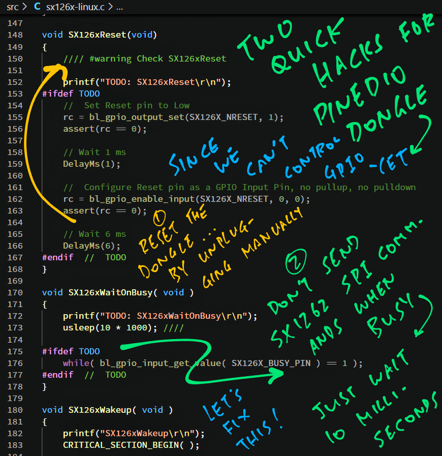
We found some sneaky workarounds to control LoRa SX1262 without GPIO…
DIO1: Because we don’t support GPIO Interrupts (yet), we poll the SX1262 Status every second to check if a LoRa Packet has been received.
BUSY: Instead of reading this pin to check if SX1262 is busy, we sleep 10 milliseconds.
NRESET: To reset the SX1262 module, we manually unplug PineDio USB and plug it back in.
These sneaky hacks will need to be fixed by calling the GPIO Interface.
What needs to be fixed for GPIO?
We need to mod these functions to call the CH341 GPIO Interface…
Initialise the GPIO Pins: SX126xIoInit
Register GPIO Interrupt Handler for DIO1: SX126xIoIrqInit
Reset SX1262 via GPIO: SX126xReset
void SX126xReset(void) {
    //  TODO: Set Reset pin to Low
    //  rc = bl_gpio_output_set(SX126X_NRESET, 1);
    //  assert(rc == 0);

    //  Wait 1 ms
    DelayMs(1);

    //  TODO: Configure Reset pin as a GPIO Input Pin, no pullup, no pulldown
    //  rc = bl_gpio_enable_input(SX126X_NRESET, 0, 0);
    //  assert(rc == 0);

    //  Wait 6 ms
    DelayMs(6);
}
Check SX1262 Busy State via GPIO: SX126xWaitOnBusy
(SX126xWaitOnBusy is called by SX126xCheckDeviceReady, which wakes up SX1262 before checking if SX1262 is busy)
void SX126xWaitOnBusy(void) {
  //  TODO: Fix the GPIO check for busy state.
  //  while( bl_gpio_input_get_value( SX126X_BUSY_PIN ) == 1 );

  //  Meanwhile we sleep 10 milliseconds
  usleep(10 * 1000);
}
Get DIO1 Pin State: SX126xGetDio1PinState
uint32_t SX126xGetDio1PinState(void) {
  //  TODO: Read and return DIO1 Pin State
  //  return bl_gpio_input_get_value( SX126X_DIO1 );

  //  Meanwhile we always return 0
  return 0;
}
When we have implemented GPIO Interrupts in our driver, we can remove the Event Polling. And we run a Background Thread to handle LoRa Events.
Here’s how we’ll do multithreading…
How will we receive LoRa Messages with GPIO Interrupts?
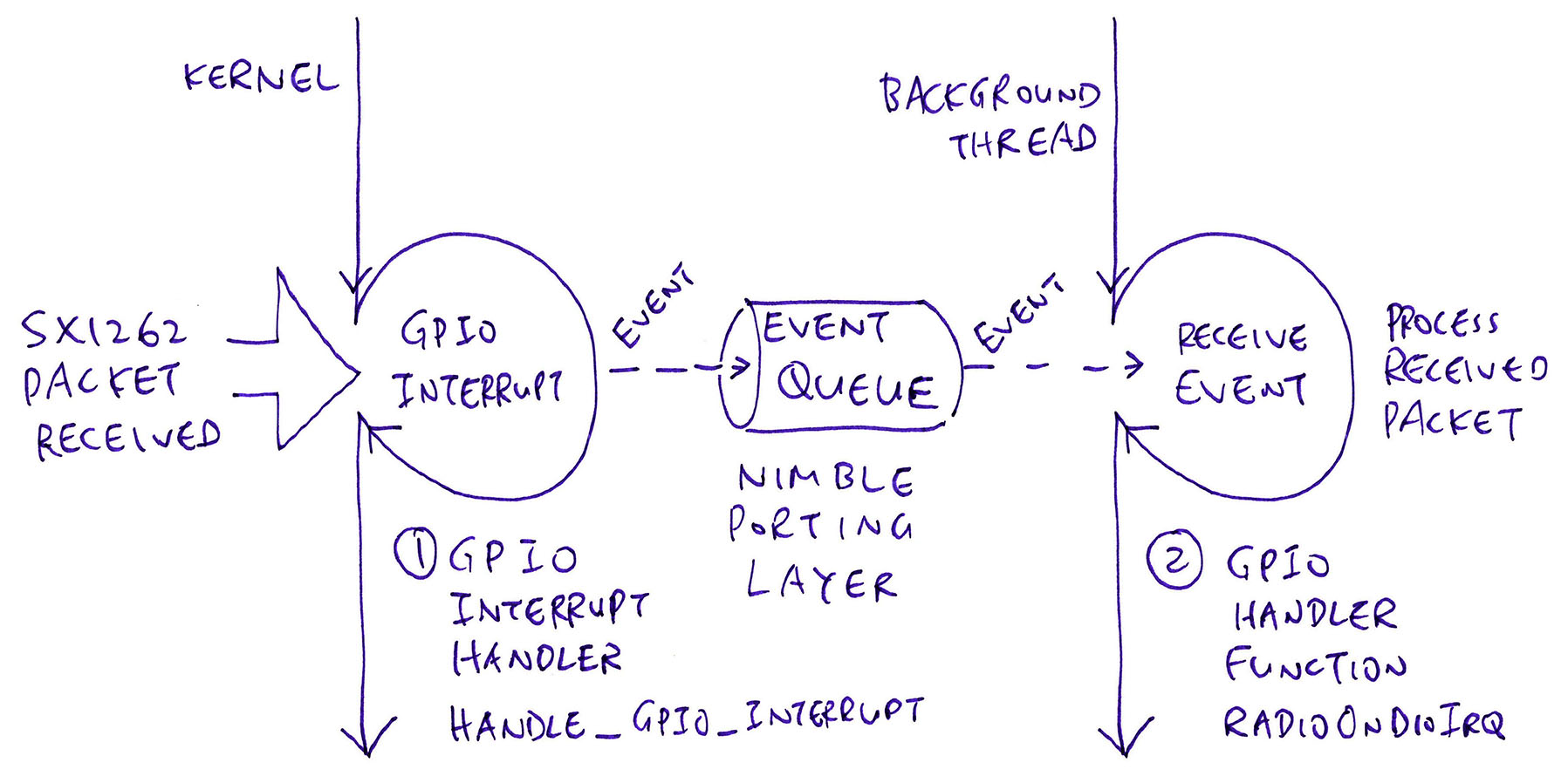
After we have implemented GPIO Interrupts in our PineDio USB Driver, this is how we’ll receive LoRa Messages (see pic above)…
When SX1262 receives a LoRa Message, it triggers a GPIO Interrupt on Pin DIO1
CH341 Driver forwards the GPIO Interrupt to our Interrupt Handler Function handle_gpio_interrupt
handle_gpio_interrupt enqueues an Event into our Event Queue
Our Background Thread removes the Event from the Event Queue and calls RadioOnDioIrq to process the received LoRa Message
We handle GPIO Interrupts the same way in our LoRa SX1262 Driver for BL602…
Why do we need a Background Thread?
This will allow our LoRa Application to run without blocking (waiting) on incoming LoRa Messages.
This is especially useful when we implement LoRaWAN on PineDio USB, because LoRaWAN needs to handle asynchronous messages in the background.
(Like when we join a LoRaWAN Network)
How will we implement the Background Thread and Event Queue?
We’ll call NimBLE Porting Layer, the open source library for Multithreading Functions…
Which has been compiled into our PineDio USB Driver…
The code below shall be updated to start the Background Thread: main.c
/// TODO: Create a Background Thread to handle LoRa Events
static void create_task(void) {
  //  Init the Event Queue
  ble_npl_eventq_init(&event_queue);

  //  Init the Event
  ble_npl_event_init(
    &event,        //  Event
    handle_event,  //  Event Handler Function
    NULL           //  Argument to be passed to Event Handler
  );

  //  TODO: Create a Background Thread to process the Event Queue
  //  nimble_port_freertos_init(task_callback);
}
And we shall implement the GPIO Interrupt Handler Function handle_gpio_interrupt for Linux.
(We don’t need to code the Event Queue, it has been done here)
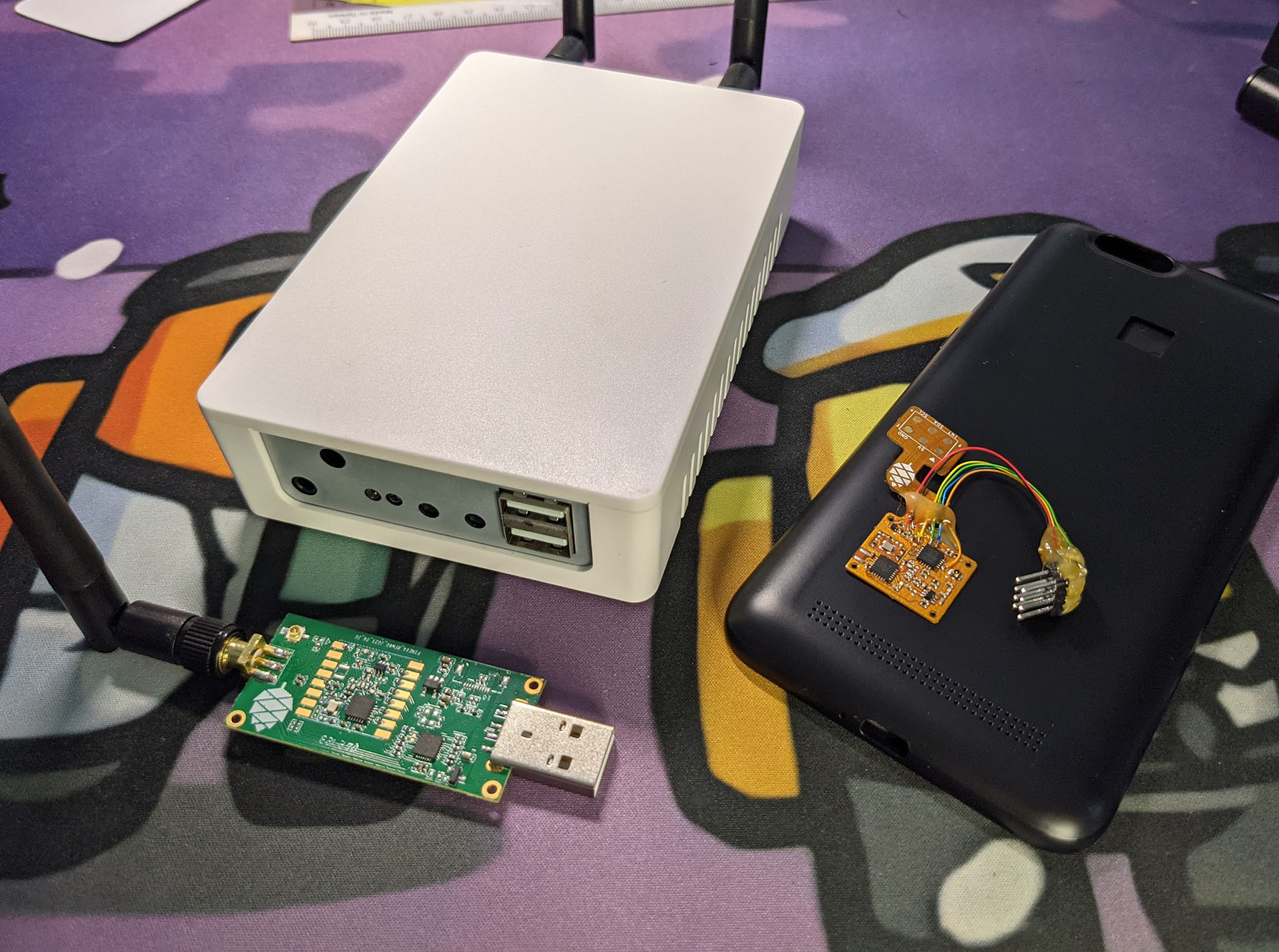
PineDio LoRa Family: PineDio Gateway, PinePhone Backplate and USB Adapter
Now that we have a Basic LoRa Driver for PineDio USB, we can explore all kinds of fun possibilities…
Merge the PineDio USB Driver back into BL602 IoT SDK
(So we can maintain a single LoRa Driver for for PineDio USB and PineDio Stack BL604)
UPDATE: We have merged PineDio USB Driver into BL602 IoT SDK!
Implement LoRaWAN on PineDio USB
(So we can connect Pinebook Pro to The Things Network and Helium)
Explore LoRa Mesh Networks for PineDio USB…
Meshtastic (Data Mesh), QMesh (Voice Mesh), Mycelium Mesh (Text Mesh)
Test PineDio USB with PineDio LoRa Gateway…
PinePhone LoRa Backplate (pic above) is an intriguing accessory…
The Backplate connects PinePhone to LoRa SX1262 via ATtiny84… Which runs an Arduino I2C-To-SPI Bridge!
(Our PineDio USB Driver might run on PinePhone if we talk to I2C instead of SPI)
Lemme know what you would like to see!
Many Thanks to my GitHub Sponsors for supporting my work! This article wouldn’t have been possible without your support.
Got a question, comment or suggestion? Create an Issue or submit a Pull Request here…
To install CH341 SPI Driver on Pinebook Pro Manjaro Arm64…
## Install DKMS so that we may load Kernel Drivers dynamically
sudo pacman -Syu dkms base-devel --needed

## Install Kernel Headers for Manjaro: https://linuxconfig.org/manjaro-linux-kernel-headers-installation
uname -r
## Should show "5.14.12-1-MANJARO-ARM" or similar
sudo pacman -S linux-headers
pacman -Q | grep headers
## Should show "linux-headers 5.14.12-1" or similar

## Reboot to be safe
sudo reboot

## Install CH341 SPI Driver
git clone https://codeberg.org/JF002/spi-ch341-usb
pushd spi-ch341-usb
## TODO: Edit Makefile and change...
##   KERNEL_DIR  = /usr/src/linux-headers-$(KVERSION)/
## To...
##   KERNEL_DIR  = /lib/modules/$(KVERSION)/build
make
sudo make install
popd

## Unload the CH341 Non-SPI Driver if it has been automatically loaded
lsmod | grep ch341
sudo rmmod ch341

## Load the CH341 SPI Driver
sudo modprobe spi-ch341-usb
Then do this…
Plug in PineDio USB
Check that the CH341 SPI Driver has been correctly loaded…
dmesgWe should see…
ch341_gpio_probe:
registered GPIOs from 496 to 511
The CH341 SPI Driver has been loaded successfully.
If we see…
spi_ch341_usb:
loading out-of-tree module taints kernel
It means the older CH341 Non-SPI Driver has been loaded.
To remove the older CH341 Non-SPI Driver…
Unplug PineDio USB
Enter…
## Unload the CH341 Non-SPI Driver
sudo rmmod ch341
Plug in PineDio USB
Enter…
dmesgAnd recheck the messages.
Whenever we reboot our computer…
Plug in PineDio USB
Check that the CH341 SPI Driver has been correctly loaded…
dmesgWe should see…
ch341_gpio_probe:
registered GPIOs from 496 to 511
The CH341 SPI Driver has been loaded successfully.
If we see…
spi_ch341_usb:
loading out-of-tree module taints kernel
It means the older CH341 Non-SPI Driver has been loaded.
To remove the older CH341 Non-SPI Driver…
Unplug PineDio USB
Enter…
## Unload the CH341 Non-SPI Driver
sudo rmmod ch341
Plug in PineDio USB
Enter…
dmesgAnd recheck the messages.
To build PineDio USB Driver on Pinebook Pro Manjaro Arm64…
Follow the instructions in the previous section to install CH341 SPI Driver.
Check that the CH341 SPI Driver has been loaded. (dmesg)
Enter at the command prompt…
## Download PineDio USB Driver
git clone --recursive https://github.com/lupyuen/lora-sx1262
cd lora-sx1262

## TODO: Edit src/main.c and uncomment
## READ_REGISTERS, SEND_MESSAGE or RECEIVE_MESSAGE.
## See "PineDio USB Operations" below.

## TODO: Edit src/main.c and update the LoRa Parameters.
## See "LoRa Parameters" above.

## Build PineDio USB Driver
make

## Run PineDio USB Driver Demo
sudo ./lora-sx1262The PineDio USB Demo supports 3 operations…
Read SX1262 Registers:
Edit src/main.c and uncomment…
#define READ_REGISTERSSend LoRa Message:
Edit src/main.c and uncomment…
#define SEND_MESSAGEReceive LoRa Message:
Edit src/main.c and uncomment…
#define RECEIVE_MESSAGEIn this section we explain the Platform-Independent (Linux and BL602) Radio Functions, which are defined in radio.c
RadioInit: Initialise LoRa SX1262
RadioSetChannel: Set LoRa Frequency
RadioSetTxConfig: Set LoRa Transmit Configuration
RadioSetRxConfig: Set LoRa Receive Configuration
RadioSend: Transmit a LoRa Message
RadioRx: Receive one LoRa Message
RadioIrqProcess: Process Transmit and Receive Interrupts
RadioSleep: Switch SX1262 to low-power sleep mode
RadioInit initialises the LoRa SX1262 Module: radio.c
void RadioInit( RadioEvents_t *events ) {
  //  We copy the Event Callbacks from "events", because
  //  "events" may be stored on the stack
  assert(events != NULL);
  memcpy(&RadioEvents, events, sizeof(RadioEvents));
  //  Previously: RadioEvents = events;
The function begins by copying the list of Radio Event Callbacks…
TxDone: Called when a LoRa Message has been transmitted
RxDone: Called when a LoRa Message has been received
TxTimeout: Called upon timeout when transmitting a LoRa Message
RxTimeout: Called upon timeout when receiving a LoRa Message
RxError: Called when a LoRa Message has been received with CRC Error
This differs from the Semtech Reference Implementation, which copies the pointer to RadioEvents_t instead of the entire RadioEvents_t.
(Which causes problems when RadioEvents_t lives on the stack)
Next we init the SPI and GPIO Ports, wake up the LoRa Module, and init the TCXO Control and RF Switch Control.
  //  Init SPI and GPIO Ports, wake up the LoRa Module,
  //  init TCXO Control and RF Switch Control.
SX126xInit( RadioOnDioIrq );(RadioOnDioIrq is explained here)
We set the LoRa Module to Standby Mode…
  //  Set LoRa Module to standby mode
  SX126xSetStandby( STDBY_RC );
We set the Power Regulation: LDO or DC-DC…
  //  TODO: Declare the power regulation used to power the device
  //  This command allows the user to specify if DC-DC or LDO is used for power regulation.
  //  Using only LDO implies that the Rx or Tx current is doubled

  //  #warning SX126x is set to LDO power regulator mode (instead of DC-DC)
  //  SX126xSetRegulatorMode( USE_LDO );   //  Use LDO

  //  #warning SX126x is set to DC-DC power regulator mode (instead of LDO)
SX126xSetRegulatorMode( USE_DCDC ); // Use DC-DC(SX126xSetRegulatorMode is defined here)
This depends on how our LoRa Module is wired for power.
For now we’re using DC-DC Power Regulation. (To be verified)
(More about LDO vs DC-DC Power Regulation)
We set the Base Addresses of the Read and Write Buffers to 0…
  //  Set the base addresses of the Read and Write Buffers to 0
SX126xSetBufferBaseAddress( 0x00, 0x00 );(SX126xSetBufferBaseAddress is defined here)
The Read and Write Buffers are accessed by sx126x_read_buffer and sx126x_write_buffer.
We set the Transmit Power and the Ramp Up Time…
  //  TODO: Set the correct transmit power and ramp up time
  SX126xSetTxParams( 22, RADIO_RAMP_3400_US );
// TODO: Previously: SX126xSetTxParams( 0, RADIO_RAMP_200_US );(SX126xSetTxParams is defined here)
Ramp Up Time is the duration (in microseconds) we need to wait for SX1262’s Power Amplifier to ramp up (charge up) to the configured Transmit Power.
For easier testing we have set the Transmit Power to 22 dBm (highest power) and Ramp Up Time to 3400 microseconds (longest duration).
(To give sufficient time for the Power Amplifier to ramp up to the highest Transmit Power)
After testing we should revert to the Default Transmit Power (0) and Ramp Up Time (200 microseconds).
(More about the Transmit Power)
(Over Current Protection in SX126xSetTxParams)
We configure which LoRa Events will trigger interrupts on each DIO Pin…
  //  Set the DIO Interrupt Events:
  //  All LoRa Events will trigger interrupts on DIO1
  SX126xSetDioIrqParams(
    IRQ_RADIO_ALL,   //  Interrupt Mask
    IRQ_RADIO_ALL,   //  Interrupt Events for DIO1
    IRQ_RADIO_NONE,  //  Interrupt Events for DIO2
    IRQ_RADIO_NONE   //  Interrupt Events for DIO3
);(SX126xSetDioIrqParams is defined here)
(All LoRa Events will trigger interrupts on DIO1)
We define the SX1262 Registers that will be restored from Retention Memory when waking up from Warm Start Mode…
  //  Add registers to the retention list (4 is the maximum possible number)
  RadioAddRegisterToRetentionList( REG_RX_GAIN );
RadioAddRegisterToRetentionList( REG_TX_MODULATION );(RadioAddRegisterToRetentionList is defined here)
Finally we init the Timeout Timers (from NimBLE Porting Layer) for Transmit Timeout and Receive Timeout…
  //  Initialize driver timeout timers
  TimerInit( &TxTimeoutTimer, RadioOnTxTimeoutIrq );
  TimerInit( &RxTimeoutTimer, RadioOnRxTimeoutIrq );

  //  Interrupt not fired yet
  IrqFired = false;
}RadioSetChannel sets the LoRa Frequency: radio.c
void RadioSetChannel( uint32_t freq ) {
  SX126xSetRfFrequency( freq );
}
RadioSetChannel passes the LoRa Frequency (like 923000000 for 923 MHz) to SX126xSetRfFrequency.
SX126xSetRfFrequency is defined as follows: sx126x.c
void SX126xSetRfFrequency( uint32_t frequency ) {
  uint8_t buf[4];
  if( ImageCalibrated == false ) {
    SX126xCalibrateImage( frequency );
    ImageCalibrated = true;
  }
  uint32_t freqInPllSteps = SX126xConvertFreqInHzToPllStep( frequency );
  buf[0] = ( uint8_t )( ( freqInPllSteps >> 24 ) & 0xFF );
  buf[1] = ( uint8_t )( ( freqInPllSteps >> 16 ) & 0xFF );
  buf[2] = ( uint8_t )( ( freqInPllSteps >> 8 ) & 0xFF );
  buf[3] = ( uint8_t )( freqInPllSteps & 0xFF );
  SX126xWriteCommand( RADIO_SET_RFFREQUENCY, buf, 4 );
}(SX126xCalibrateImage is defined here)
(SX126xConvertFreqInHzToPllStep is defined here)
(SX126xWriteCommand is defined here)
RadioSetTxConfig sets the LoRa Transmit Configuration: radio.c
void RadioSetTxConfig( RadioModems_t modem, int8_t power, uint32_t fdev,
  uint32_t bandwidth, uint32_t datarate,
  uint8_t coderate, uint16_t preambleLen,
  bool fixLen, bool crcOn, bool freqHopOn,
  uint8_t hopPeriod, bool iqInverted, uint32_t timeout ) {

  //  LoRa Modulation or FSK Modulation?
  switch( modem ) {
    case MODEM_FSK:
      //  Omitted: FSK Modulation
      ...
Since we’re using LoRa Modulation instead of FSK Modulation, we skip the section on FSK Modulation.
We begin by populating the Modulation Parameters: Spreading Factor, Bandwidth and Coding Rate…
    case MODEM_LORA:
      //  LoRa Modulation
      SX126x.ModulationParams.PacketType =
        PACKET_TYPE_LORA;
      SX126x.ModulationParams.Params.LoRa.SpreadingFactor =
        ( RadioLoRaSpreadingFactors_t ) datarate;
      SX126x.ModulationParams.Params.LoRa.Bandwidth =
        Bandwidths[bandwidth];
      SX126x.ModulationParams.Params.LoRa.CodingRate =
        ( RadioLoRaCodingRates_t )coderate;
Depending on the LoRa Parameters, we optimise for Low Data Rate…
      //  Optimise for Low Data Rate
      if( ( ( bandwidth == 0 ) && ( ( datarate == 11 ) || ( datarate == 12 ) ) ) ||
      ( ( bandwidth == 1 ) && ( datarate == 12 ) ) ) {
        SX126x.ModulationParams.Params.LoRa.LowDatarateOptimize = 0x01;
      } else {
        SX126x.ModulationParams.Params.LoRa.LowDatarateOptimize = 0x00;
      }
Next we populate the Packet Parameters: Preamble Length, Header Type, Payload Length, CRC Mode and Invert IQ…
      //  Populate Packet Type
      SX126x.PacketParams.PacketType = PACKET_TYPE_LORA;

      //  Populate Preamble Length
      if( ( SX126x.ModulationParams.Params.LoRa.SpreadingFactor == LORA_SF5 ) ||
        ( SX126x.ModulationParams.Params.LoRa.SpreadingFactor == LORA_SF6 ) ) {
        if( preambleLen < 12 ) {
          SX126x.PacketParams.Params.LoRa.PreambleLength = 12;
        } else {
          SX126x.PacketParams.Params.LoRa.PreambleLength = preambleLen;
        }
      } else {
        SX126x.PacketParams.Params.LoRa.PreambleLength = preambleLen;
      }

      //  Populate Header Type, Payload Length, CRC Mode and Invert IQ
      SX126x.PacketParams.Params.LoRa.HeaderType =
        ( RadioLoRaPacketLengthsMode_t )fixLen;
      SX126x.PacketParams.Params.LoRa.PayloadLength =
        MaxPayloadLength;
      SX126x.PacketParams.Params.LoRa.CrcMode =
        ( RadioLoRaCrcModes_t )crcOn;
      SX126x.PacketParams.Params.LoRa.InvertIQ =
        ( RadioLoRaIQModes_t )iqInverted;
We set the LoRa Module to Standby Mode and configure it for LoRa Modulation (or FSK Modulation)…
      //  Set LoRa Module to Standby Mode
      RadioStandby( );

      //  Configure LoRa Module for LoRa Modulation (or FSK Modulation)
      RadioSetModem(
        ( SX126x.ModulationParams.PacketType == PACKET_TYPE_GFSK )
        ? MODEM_FSK
        : MODEM_LORA
);(RadioStandby is defined here)
(RadioSetModem is defined here)
We configure the LoRa Module with the Modulation Parameters and Packet Parameters…
      //  Configure Modulation Parameters
      SX126xSetModulationParams( &SX126x.ModulationParams );

      //  Configure Packet Parameters
      SX126xSetPacketParams( &SX126x.PacketParams );
      break;
}(SX126xSetModulationParams is defined here)
(SX126xSetPacketParams is defined here)
This is a Workaround for Modulation Quality with 500 kHz Bandwidth…
  // WORKAROUND - Modulation Quality with 500 kHz LoRa Bandwidth, see DS_SX1261-2_V1.2 datasheet chapter 15.1
  if( ( modem == MODEM_LORA ) && ( SX126x.ModulationParams.Params.LoRa.Bandwidth == LORA_BW_500 ) ) {
    SX126xWriteRegister(
      REG_TX_MODULATION,
      SX126xReadRegister( REG_TX_MODULATION ) & ~( 1 << 2 )
    );
  } else {
    SX126xWriteRegister(
      REG_TX_MODULATION,
      SX126xReadRegister( REG_TX_MODULATION ) | ( 1 << 2 )
    );
  }
// WORKAROUND END(SX126xWriteRegister is defined here)
(SX126xReadRegister is defined here)
We finish by setting the Transmit Power and Transmit Timeout…
  //  Set Transmit Power
  SX126xSetRfTxPower( power );

  //  Set Transmit Timeout
  TxTimeout = timeout;
}
SX126xSetRfTxPower is defined in sx126x-linux.c…
void SX126xSetRfTxPower( int8_t power ) {
  //  TODO: Previously: SX126xSetTxParams( power, RADIO_RAMP_40_US );
  SX126xSetTxParams( power, RADIO_RAMP_3400_US );  //  TODO
}
For easier testing we have set the Ramp Up Time to 3400 microseconds (longest duration).
After testing we should revert to the Default Ramp Up Time (40 microseconds).
RadioSetRxConfig sets the LoRa Receive Configuration: radio.c
void RadioSetRxConfig( RadioModems_t modem, uint32_t bandwidth,
  uint32_t datarate, uint8_t coderate,
  uint32_t bandwidthAfc, uint16_t preambleLen,
  uint16_t symbTimeout, bool fixLen,
  uint8_t payloadLen,
  bool crcOn, bool freqHopOn, uint8_t hopPeriod,
  bool iqInverted, bool rxContinuous ) {

  //  Set Symbol Timeout
  RxContinuous = rxContinuous;
  if( rxContinuous == true ) {
    symbTimeout = 0;
  }

  //  Set Max Payload Length
  if( fixLen == true ) {
    MaxPayloadLength = payloadLen;
  }
  else {
    MaxPayloadLength = 0xFF;
  }
We begin by setting the Symbol Timeout and Max Payload Length.
Since we’re using LoRa Modulation instead of FSK Modulation, we skip the section on FSK Modulation…
  //  LoRa Modulation or FSK Modulation?
  switch( modem )
  {
    case MODEM_FSK:
      //  Omitted: FSK Modulation
      ...
We populate the Modulation Parameters: Spreading Factor, Bandwidth and Coding Rate…
    case MODEM_LORA:
      //  LoRa Modulation
      SX126xSetStopRxTimerOnPreambleDetect( false );
      SX126x.ModulationParams.PacketType =
        PACKET_TYPE_LORA;
      SX126x.ModulationParams.Params.LoRa.SpreadingFactor =
        ( RadioLoRaSpreadingFactors_t )datarate;
      SX126x.ModulationParams.Params.LoRa.Bandwidth =
        Bandwidths[bandwidth];
      SX126x.ModulationParams.Params.LoRa.CodingRate =
        ( RadioLoRaCodingRates_t )coderate;
Depending on the LoRa Parameters, we optimise for Low Data Rate…
      //  Optimise for Low Data Rate
      if( ( ( bandwidth == 0 ) && ( ( datarate == 11 ) || ( datarate == 12 ) ) ) ||
      ( ( bandwidth == 1 ) && ( datarate == 12 ) ) ) {
        SX126x.ModulationParams.Params.LoRa.LowDatarateOptimize = 0x01;
      } else {
        SX126x.ModulationParams.Params.LoRa.LowDatarateOptimize = 0x00;
      }
We populate the Packet Parameters: Preamble Length, Header Type, Payload Length, CRC Mode and Invert IQ…
      //  Populate Packet Type
      SX126x.PacketParams.PacketType = PACKET_TYPE_LORA;

      //  Populate Preamble Length
      if( ( SX126x.ModulationParams.Params.LoRa.SpreadingFactor == LORA_SF5 ) ||
          ( SX126x.ModulationParams.Params.LoRa.SpreadingFactor == LORA_SF6 ) ){
        if( preambleLen < 12 ) {
          SX126x.PacketParams.Params.LoRa.PreambleLength = 12;
        } else {
          SX126x.PacketParams.Params.LoRa.PreambleLength = preambleLen;
        }
      } else {
        SX126x.PacketParams.Params.LoRa.PreambleLength = preambleLen;
      }

      //  Populate Header Type, Payload Length, CRC Mode and Invert IQ
      SX126x.PacketParams.Params.LoRa.HeaderType =
        ( RadioLoRaPacketLengthsMode_t )fixLen;
      SX126x.PacketParams.Params.LoRa.PayloadLength =
        MaxPayloadLength;
      SX126x.PacketParams.Params.LoRa.CrcMode =
        ( RadioLoRaCrcModes_t )crcOn;
      SX126x.PacketParams.Params.LoRa.InvertIQ =
        ( RadioLoRaIQModes_t )iqInverted;
We set the LoRa Module to Standby Mode and configure it for LoRa Modulation (or FSK Modulation)…
      //  Set LoRa Module to Standby Mode
      RadioStandby( );

      //  Configure LoRa Module for LoRa Modulation (or FSK Modulation)
      RadioSetModem(
          ( SX126x.ModulationParams.PacketType == PACKET_TYPE_GFSK )
          ? MODEM_FSK
          : MODEM_LORA
);(RadioStandby is defined here)
(RadioSetModem is defined here)
We configure the LoRa Module with the Modulation Parameters, Packet Parameters and Symbol Timeout…
      //  Configure Modulation Parameters
      SX126xSetModulationParams( &SX126x.ModulationParams );

      //  Configure Packet Parameters
      SX126xSetPacketParams( &SX126x.PacketParams );

      //  Configure Symbol Timeout
SX126xSetLoRaSymbNumTimeout( symbTimeout );(SX126xSetModulationParams is defined here)
(SX126xSetPacketParams is defined here)
(SX126xSetLoRaSymbNumTimeout is defined here)
This is a Workaround that optimises the Inverted IQ Operation…
      // WORKAROUND - Optimizing the Inverted IQ Operation, see DS_SX1261-2_V1.2 datasheet chapter 15.4
      if( SX126x.PacketParams.Params.LoRa.InvertIQ == LORA_IQ_INVERTED ) {
        SX126xWriteRegister(
          REG_IQ_POLARITY,
          SX126xReadRegister( REG_IQ_POLARITY ) & ~( 1 << 2 )
        );
      } else {
        SX126xWriteRegister(
          REG_IQ_POLARITY,
          SX126xReadRegister( REG_IQ_POLARITY ) | ( 1 << 2 )
        );
      }
// WORKAROUND END(SX126xWriteRegister is defined here)
(SX126xReadRegister is defined here)
We finish by setting the Receive Timeout to No Timeout (always receiving)…
      // Timeout Max, Timeout handled directly in SetRx function
      RxTimeout = 0xFFFF;
      break;
  }
}RadioSend transmits a LoRa Message: radio.c
void RadioSend( uint8_t *buffer, uint8_t size ) {

  //  Set the DIO Interrupt Events:
  //  Transmit Done and Transmit Timeout
  //  will trigger interrupts on DIO1
  SX126xSetDioIrqParams(
    IRQ_TX_DONE | IRQ_RX_TX_TIMEOUT,  //  Interrupt Mask
    IRQ_TX_DONE | IRQ_RX_TX_TIMEOUT,  //  Interrupt Events for DIO1
    IRQ_RADIO_NONE,  //  Interrupt Events for DIO2
    IRQ_RADIO_NONE   //  Interrupt Events for DIO3
);(SX126xSetDioIrqParams is defined here)
We begin by configuring which LoRa Events will trigger interrupts on each DIO Pin.
(Transmit Done and Transmit Timeout will trigger interrupts on DIO1)
Next we configure the Packet Parameters…
  //  Populate the payload length
  if( SX126xGetPacketType( ) == PACKET_TYPE_LORA ) {
    SX126x.PacketParams.Params.LoRa.PayloadLength = size;
  } else {
    SX126x.PacketParams.Params.Gfsk.PayloadLength = size;
  }
  //  Configure the packet parameters
SX126xSetPacketParams( &SX126x.PacketParams );(SX126xGetPacketType is defined here)
(SX126xSetPacketParams is defined here)
We finish by sending the Message Payload and starting the Transmit Timer…
  //  Send message payload
  SX126xSendPayload( buffer, size, 0 );

  //  Start Transmit Timer
  TimerStart( &TxTimeoutTimer, TxTimeout );
}SX126xSendPayload is defined below: sx126x.c
///  Send message payload
void SX126xSendPayload( uint8_t *payload, uint8_t size, uint32_t timeout ) {
  //  Copy message payload to Transmit Buffer
  SX126xSetPayload( payload, size );

  //  Transmit the buffer
  SX126xSetTx( timeout );
}This code copies the Message Payload to the SX1262 Transmit Buffer and transmits the message.
SX126xSetPayload copies to the Transmit Buffer by calling SX126xWriteBuffer: sx126x.c
/// Copy message payload to Transmit Buffer
void SX126xSetPayload( uint8_t *payload, uint8_t size ) {
  //  Copy message payload to Transmit Buffer
  SX126xWriteBuffer( 0x00, payload, size );
}
SX126xWriteBuffer wakes up the LoRa Module, writes to the Transmit Buffer and waits for the operation to be completed: sx126x.c
/// Copy message payload to Transmit Buffer
void SX126xWriteBuffer( uint8_t offset, uint8_t *buffer, uint8_t size ) {
  //  Wake up SX1262 if sleeping
  SX126xCheckDeviceReady( );

  //  Copy message payload to Transmit Buffer
  int rc = sx126x_write_buffer(NULL, offset, buffer, size);
  assert(rc == 0);

  //  Wait for SX1262 to be ready
  SX126xWaitOnBusy( );
}(SX126xCheckDeviceReady is defined here)
(sx126x_write_buffer is explained here)
(SX126xWaitOnBusy is defined here)
When the LoRa Message is transmitted (successfully or unsuccessfully), the LoRa Module triggers a DIO1 Interrupt.
Our driver calls RadioIrqProcess to process the interrupt. (See this)
RadioRx receives a single LoRa Message: radio.c
void RadioRx( uint32_t timeout ) {

  //  Set the DIO Interrupt Events:
  //  All LoRa Events will trigger interrupts on DIO1
  SX126xSetDioIrqParams(
    IRQ_RADIO_ALL,   //  Interrupt Mask
    IRQ_RADIO_ALL,   //  Interrupt Events for DIO1
    IRQ_RADIO_NONE,  //  Interrupt Events for DIO2
    IRQ_RADIO_NONE   //  Interrupt Events for DIO3
);(SX126xSetDioIrqParams is defined here)
We begin by configuring which LoRa Events will trigger interrupts on each DIO Pin.
(All LoRa Events will trigger interrupts on DIO1)
We start the Receive Timer to catch Receive Timeouts…
  //  Start the Receive Timer
  if( timeout != 0 ) {
    TimerStart( &RxTimeoutTimer, timeout );
}Now we begin to receive a LoRa Message continuously, or until a timeout occurs…
  if( RxContinuous == true ) {
    //  Receive continuously
    SX126xSetRx( 0xFFFFFF ); // Rx Continuous
  } else {
    //  Receive with timeout
    SX126xSetRx( RxTimeout << 6 );
  }
}
SX126xSetRx enters Receive Mode like so: sx126x.c
void SX126xSetRx( uint32_t timeout ) {
  uint8_t buf[3];

  //  Remember we're in Receive Mode
  SX126xSetOperatingMode( MODE_RX );

  //  Configure Receive Gain
  SX126xWriteRegister( REG_RX_GAIN, 0x94 ); // default gain

  //  Enter Receive Mode
  buf[0] = ( uint8_t )( ( timeout >> 16 ) & 0xFF );
  buf[1] = ( uint8_t )( ( timeout >> 8 ) & 0xFF );
  buf[2] = ( uint8_t )( timeout & 0xFF );
  SX126xWriteCommand( RADIO_SET_RX, buf, 3 );
}(SX126xSetOperatingMode is defined here)
(SX126xWriteRegister is defined here)
(SX126xWriteCommand is defined here)
When a LoRa Message is received (successfully or unsuccessfully), the LoRa Module triggers a DIO1 Interrupt.
Our driver calls RadioIrqProcess to process the interrupt, which is explained next…
RadioIrqProcess processes the interrupts that are triggered when a LoRa Message is transmitted and received: radio.c
/// Process Transmit and Receive Interrupts.
/// For BL602: Must be run in the Application
/// Task Context, not Interrupt Context because
/// we will call printf and SPI Functions here.
void RadioIrqProcess( void ) {

  //  Remember and clear Interrupt Flag
  CRITICAL_SECTION_BEGIN( );
  const bool isIrqFired = IrqFired;
  IrqFired = false;
  CRITICAL_SECTION_END( );
(Note: Critical Sections are not yet implemented)
The function begins by copying the Interrupt Flag and clearing the flag.
(The Interrupt Flag is set by RadioOnDioIrq)
The rest of the function will run only if the Interrupt Flag was originally set…
  //  IrqFired must be true to process interrupts
  if( isIrqFired == true ) {
    //  Get the Interrupt Status
    uint16_t irqRegs = SX126xGetIrqStatus( );

    //  Clear the Interrupt Status
SX126xClearIrqStatus( irqRegs );(SX126xGetIrqStatus is defined here)
(SX126xClearIrqStatus is defined here)
This code fetches the Interrupt Status from the LoRa Module and clears the Interrupt Status.
If DIO1 is still High, we set the Interrupt Flag for future processing…
    //  Check if DIO1 pin is High. If it is the case revert IrqFired to true
    CRITICAL_SECTION_BEGIN( );
    if( SX126xGetDio1PinState( ) == 1 ) {
      IrqFired = true;
    }
    CRITICAL_SECTION_END( );
Interrupt Status tells us which LoRa Events have just occurred. We handle the LoRa Events accordingly…
Transmit Done
Receive Done
CAD Done
Transmit / Receive Timeout
Preamble Detected
Sync Word Valid
Header Valid
Header Error
When the LoRa Module has transmitted a LoRa Message successfully, we stop the Transmit Timer and call the Callback Function for Transmit Done: radio.c
    //  If a LoRa Message was transmitted successfully...
    if( ( irqRegs & IRQ_TX_DONE ) == IRQ_TX_DONE ) {

      //  Stop the Transmit Timer
      TimerStop( &TxTimeoutTimer );

      //!< Update operating mode state to a value lower than \ref MODE_STDBY_XOSC
      SX126xSetOperatingMode( MODE_STDBY_RC );

      //  Call the Callback Function for Transmit Done
      if( ( RadioEvents.TxDone != NULL ) ) {
        RadioEvents.TxDone( );
      }
}(SX126xSetOperatingMode is defined here)
TxDone points to the on_tx_done Callback Function that we’ve seen earlier.
When the LoRa Module receives a LoRa Message, we stop the Receive Timer: radio.c
    //  If a LoRa Message was received...
    if( ( irqRegs & IRQ_RX_DONE ) == IRQ_RX_DONE ) {

      //  Stop the Receive Timer
      TimerStop( &RxTimeoutTimer );
In case of CRC Error, we call the Callback Function for Receive Error…
      if( ( irqRegs & IRQ_CRC_ERROR ) == IRQ_CRC_ERROR ) {

        //  If the received message has CRC Error...
        if( RxContinuous == false ) {
          //!< Update operating mode state to a value lower than \ref MODE_STDBY_XOSC
          SX126xSetOperatingMode( MODE_STDBY_RC );
        }

        //  Call the Callback Function for Receive Error
        if( ( RadioEvents.RxError ) ) {
          RadioEvents.RxError( );
        }
RxError points to the on_rx_error Callback Function that we’ve seen earlier.
If the received message has no CRC Error, we do this Workaround for Implicit Header Mode Timeout Behavior…
      } else {
        //  If the received message has no CRC Error...
        uint8_t size;

        //  If we are receiving continuously...
        if( RxContinuous == false ) {
          //!< Update operating mode state to a value lower than \ref MODE_STDBY_XOSC
          SX126xSetOperatingMode( MODE_STDBY_RC );

          // WORKAROUND - Implicit Header Mode Timeout Behavior, see DS_SX1261-2_V1.2 datasheet chapter 15.3
          SX126xWriteRegister( REG_RTC_CTRL, 0x00 );
          SX126xWriteRegister(
            REG_EVT_CLR,
            SX126xReadRegister( REG_EVT_CLR ) | ( 1 << 1 )
          );
          // WORKAROUND END
}(SX126xWriteRegister is defined here)
(SX126xReadRegister is defined here)
Then we copy the Received Message Payload and get the Packet Status…
        //  Copy the Received Message Payload (max 255 bytes)
        SX126xGetPayload( RadioRxPayload, &size , 255 );

        //  Get the Packet Status:
        //  Packet Signal Strength (RSSI), Signal-to-Noise Ratio (SNR),
        //  Signal RSSI, Frequency Error
SX126xGetPacketStatus( &RadioPktStatus );(SX126xGetPacketStatus is defined here)
And we call the Callback Function for Receive Done…
        //  Call the Callback Function for Receive Done
        if( ( RadioEvents.RxDone != NULL ) ) {
          RadioEvents.RxDone(
            RadioRxPayload,
            size,
            RadioPktStatus.Params.LoRa.RssiPkt,
            RadioPktStatus.Params.LoRa.SnrPkt
          );
        }
      }
    }
RxDone points to the on_rx_done Callback Function that we’ve seen earlier.
SX126xGetPayload copies the received message payload from the SX1262 Receive Buffer: sx126x.c
/// Copy message payload from Receive Buffer
uint8_t SX126xGetPayload( uint8_t *buffer, uint8_t *size,  uint8_t maxSize ) {
  uint8_t offset = 0;

  //  Get the size and offset of the received message
  //  in the Receive Buffer
  SX126xGetRxBufferStatus( size, &offset );
  if( *size > maxSize ) {
    return 1;
  }

  //  Copy message payload from Receive Buffer
  SX126xReadBuffer( offset, buffer, *size );
  return 0;
}(SX126xGetRxBufferStatus is defined here)
SX126xReadBuffer wakes up the LoRa Module, reads from the Receive Buffer and waits for the operation to be completed: sx126x-linux.c
/// Copy message payload from Receive Buffer
void SX126xReadBuffer( uint8_t offset, uint8_t *buffer, uint8_t size ) {
  //  Wake up SX1262 if sleeping
  SX126xCheckDeviceReady( );

  //  Copy message payload from Receive Buffer
  int rc = sx126x_read_buffer(NULL, offset, buffer, size);
  assert(rc == 0);

  //  Wait for SX1262 to be ready
  SX126xWaitOnBusy( );
}(SX126xCheckDeviceReady is defined here)
(sx126x_read_buffer is explained here)
(SX126xWaitOnBusy is defined here)
Channel Activity Detection lets us detect whether there’s any ongoing transmission in a LoRa Radio Channel, in a power-efficient way.
We won’t be doing Channel Activity Detection in our driver: radio.c
    //  If Channel Activity Detection is complete...
    if( ( irqRegs & IRQ_CAD_DONE ) == IRQ_CAD_DONE ) {

      //!< Update operating mode state to a value lower than \ref MODE_STDBY_XOSC
      SX126xSetOperatingMode( MODE_STDBY_RC );

      //  Call Callback Function for CAD Done
      if( ( RadioEvents.CadDone != NULL ) ) {
        RadioEvents.CadDone( (
            ( irqRegs & IRQ_CAD_ACTIVITY_DETECTED )
            == IRQ_CAD_ACTIVITY_DETECTED
        ) );
      }
}When the LoRa Module fails to transmit a LoRa Message due to Timeout, we stop the Transmit Timer and call the Callback Function for Transmit Timeout: radio.c
    //  If a LoRa Message failed to Transmit or Receive due to Timeout...
    if( ( irqRegs & IRQ_RX_TX_TIMEOUT ) == IRQ_RX_TX_TIMEOUT ) {

      //  If the message failed to Transmit due to Timeout...
      if( SX126xGetOperatingMode( ) == MODE_TX ) {

        //  Stop the Transmit Timer
        TimerStop( &TxTimeoutTimer );

        //!< Update operating mode state to a value lower than \ref MODE_STDBY_XOSC
        SX126xSetOperatingMode( MODE_STDBY_RC );

        //  Call the Callback Function for Transmit Timeout
        if( ( RadioEvents.TxTimeout != NULL ) ) {
          RadioEvents.TxTimeout( );
        }
}(SX126xGetOperatingMode is defined here)
TxTimeout points to the on_tx_timeout Callback Function that we’ve seen earlier.
When the LoRa Module fails to receive a LoRa Message due to Timeout, we stop the Receive Timer and call the Callback Function for Receive Timeout…
      //  If the message failed to Receive due to Timeout...
      else if( SX126xGetOperatingMode( ) == MODE_RX ) {

        //  Stop the Receive Timer
        TimerStop( &RxTimeoutTimer );

        //!< Update operating mode state to a value lower than \ref MODE_STDBY_XOSC
        SX126xSetOperatingMode( MODE_STDBY_RC );

        //  Call the Callback Function for Receive Timeout
        if( ( RadioEvents.RxTimeout != NULL ) ) {
          RadioEvents.RxTimeout( );
        }
      }
    }
RxTimeout points to the on_rx_timeout Callback Function that we’ve seen earlier.
Preamble is the Radio Signal that precedes the LoRa Message. When the LoRa Module detects the Preamble Signal, it knows that it’s about to receive a LoRa Message.
We don’t need to handle the Preamble Signal, the LoRa Module does it for us: radio.c
    //  If LoRa Preamble was detected...
    if( ( irqRegs & IRQ_PREAMBLE_DETECTED ) == IRQ_PREAMBLE_DETECTED ) {
      //__NOP( );
    }
Our Receive Message Log shows that the Preamble Signal (IRQ_PREAMBLE_DETECTED) is always detected before receiving a LoRa Message.
(IRQ_PREAMBLE_DETECTED appears just before the LoRa Header: IRQ_HEADER_VALID)
Sync Words are 16-bit values that differentiate the types of LoRa Networks.
The LoRa Module detects the Sync Words when it receive a LoRa Message: radio.c
    //  If a valid Sync Word was detected...
    if( ( irqRegs & IRQ_SYNCWORD_VALID ) == IRQ_SYNCWORD_VALID ) {
      //__NOP( );
    }
Note that the Sync Word differs for LoRaWAN vs Private LoRa Networks…
//  Syncword for Private LoRa networks
#define LORA_MAC_PRIVATE_SYNCWORD                   0x1424

//  Syncword for Public LoRa networks (LoRaWAN)
#define LORA_MAC_PUBLIC_SYNCWORD 0x3444The LoRa Module checks for a valid LoRa Header when receiving a LoRa Message: radio.c
    //  If a valid Header was received...
    if( ( irqRegs & IRQ_HEADER_VALID ) == IRQ_HEADER_VALID ) {
      //__NOP( );
    }
Our Receive Message Log shows that the LoRa Header (IRQ_HEADER_VALID) is always detected before receiving a LoRa Message.
(IRQ_HEADER_VALID appears right after the Preamble Signal: IRQ_PREAMBLE_DETECTED)
When the LoRa Module detects a LoRa Header with CRC Error, we stop the Receive Timer and call the Callback Function for Receive Timeout: radio.c
    //  If a Header with CRC Error was received...
    if( ( irqRegs & IRQ_HEADER_ERROR ) == IRQ_HEADER_ERROR ) {

      //  Stop the Receive Timer
      TimerStop( &RxTimeoutTimer );

      if( RxContinuous == false ) {
        //!< Update operating mode state to a value lower than \ref MODE_STDBY_XOSC
        SX126xSetOperatingMode( MODE_STDBY_RC );
      }

      //  Call the Callback Function for Receive Timeout
      if( ( RadioEvents.RxTimeout != NULL ) ) {
        RadioEvents.RxTimeout( );
      }
    }
  }
}
RxTimeout points to the on_rx_timeout Callback Function that we’ve seen earlier.
RadioIrqProcess (as defined above) is called by RadioOnDioIrq to handle LoRa Transmit and Receive Events: radio.c
/// Callback Function for Transmit and Receive Interrupts.
/// For BL602: This function runs in the context of the
/// Background Application Task. So we are safe to call
/// printf and SPI Functions now.
void RadioOnDioIrq( struct ble_npl_event *ev ) {
  //  Set the Interrupt Flag
  IrqFired = true;

  //  BL602 Note: It's OK to process the interrupt here because we are in
  //  Application Task Context, not Interrupt Context.
  //  The Reference Implementation processes the interrupt in the main loop.
  RadioIrqProcess();
}RadioSleep switches SX1262 to low-power sleep mode: radio.c
/// Switch to Sleep Mode
void RadioSleep( void ) {
  SleepParams_t params = { 0 };
  params.Fields.WarmStart = 1;

  //  Switch to Sleep Mode and wait 2 milliseconds
  SX126xSetSleep( params );
  DelayMs( 2 );
}
SX126xSetSleep executes the Sleep Command on the LoRa Module: sx126x.c
/// Switch to Sleep Mode
void SX126xSetSleep( SleepParams_t sleepConfig ) {
  //  Switch off antenna (not used)
  SX126xAntSwOff( );

  //  Compute Sleep Parameter
  uint8_t value = (
      ( ( uint8_t )sleepConfig.Fields.WarmStart << 2 ) |
      ( ( uint8_t )sleepConfig.Fields.Reset << 1 ) |
      ( ( uint8_t )sleepConfig.Fields.WakeUpRTC )
  );

  if( sleepConfig.Fields.WarmStart == 0 ) {
    // Force image calibration
    ImageCalibrated = false;
  }

  //  Run Sleep Command
  SX126xWriteCommand( RADIO_SET_SLEEP, &value, 1 );
  SX126xSetOperatingMode( MODE_SLEEP );
}(SX126xAntSwOff is defined here)
(SX126xWriteCommand is defined here)
(SX126xSetOperatingMode is defined here)
