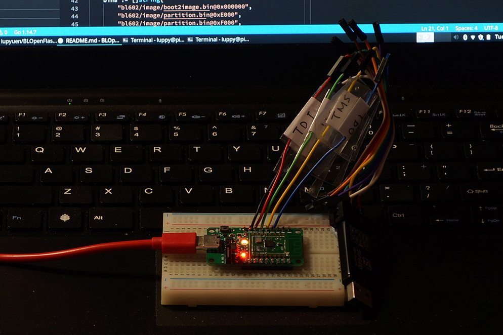
PineCone BL602 RISC-V Evaluation Board connected to Pinebook Pro
📝 6 Jan 2021
Today we shall take control of PineCone’s Onboard RGB LED in two ways…
GPIO
Pulse Width Modulation (PWM)
We’ll do this with the GPIO and PWM Demo Firmware from the BL602 IoT SDK.
Through the Demo Firmware we shall learn to call BL602’s Hardware Abstraction Layer in C to perform GPIO and PWM Functions.
If you’re new to PineCone BL602, check out my article…
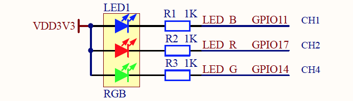
PineCone RGB LED Schematic
According to the PineCone Schematics, the onboard RGB LED is connected to these GPIO Pins…
| LED | GPIO Pin |
|---|---|
| Blue | GPIO 11 |
| Red | GPIO 17 |
| Green | GPIO 14 |
Let’s flash the GPIO Demo from the BL602 IoT SDK and interact with the above GPIO Pins…
Download the BL602 Demo Firmware Binaries…
Unzip customer_app.zip. Look for the file…
sdk_app_gpio/build_out/sdk_app_gpio.binFlash sdk_app_gpio.bin to PineCone. Follow the instructions in the article…
After flashing, flip the PineCone Jumper (IO 8) to the L Position (Like this)
Press the Reset Button.
Connect to PineCone…
For Linux:
screen /dev/ttyUSB0 2000000For macOS: Use CoolTerm (See this)
For Windows: Use putty (See this)
Alternatively: Use the Web Serial Terminal (See this)
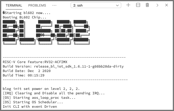
Press the RST Button on PineCone to restart the firmware.
We should see this…
Press Enter to reveal the command prompt.
Enter help to see the commands…
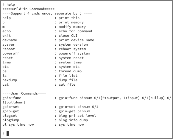
Enter these commands to set GPIO 11 (Blue), 14 (Green), 17 (Red) to output (no pullup, no pulldown)…
gpio-func 11 0 0 0
gpio-func 14 0 0 0
gpio-func 17 0 0 0
Switch off the 3 LEDs (1 = Off)…
gpio-set 11 1
gpio-set 14 1
gpio-set 17 1
Switch on and off each of the 3 LEDs: Blue, Green, Red (0 = On, 1 = Off)…
gpio-set 11 0
gpio-set 11 1

gpio-set 14 0
gpio-set 14 1

gpio-set 17 0
gpio-set 17 1
To exit screen, press Ctrl-A then k then y
Watch the GPIO Demo Video on YouTube
PineCone Jumper Schematic
According to the PineCone Schematics, the onboard jumper is connected to GPIO 8.
Can we use this command to read the jumper?
gpio-get 8Flip the jumper and check whether the value changes.
Remember to use this command to configure GPIO 8…
gpio-func 8 1 PULLUP PULLDOWN8 is the GPIO Number1 to configure the GPIO for Input (instead of output)PULLUP is 0 for No Pullup, 1 for PullupPULLDOWN is 0 for No Pulldown, 1 for PulldownPlease lemme know!
The GPIO Demo Firmware calls the GPIO Functions provided by the BL602 Hardware Abstraction Layer (HAL).
Let’s look at the BL602 GPIO Functions called by the GPIO Demo Firmware: sdk_app_gpio.bin
To designate a GPIO Pin for input or output, we call these GPIO HAL Functions: bl_gpio.h
int bl_gpio_enable_output(uint8_t pin, uint8_t pullup, uint8_t pulldown);
int bl_gpio_enable_input( uint8_t pin, uint8_t pullup, uint8_t pulldown);
pin is the GPIO Pin Number, so pin=0 refers to GPIO 0.
pullup is set to 1 if the pin should be pulled up electrically, 0 otherwise.
pulldown is set to 1 if the pin should be pulled down electrically, 0 otherwise.
Check out this sample code for GPIO Output…
To read or write a GPIO Pin, we call these GPIO HAL Functions: bl_gpio.h
int bl_gpio_output_set(uint8_t pin, uint8_t value);
int bl_gpio_input_get( uint8_t pin, uint8_t *value);
int bl_gpio_input_get_value(uint8_t pin);
pin is the GPIO Pin Number.
value is the value to be read or written (0=Low, 1=High).
bl_gpio_input_get stores the value read at the pointer passed in.
Check out this sample code for writing to GPIO…
To allow a GPIO Pin to trigger interrupts (like when a button is pressed), we call these GPIO HAL Functions: bl_gpio.h
int  bl_gpio_int_clear( uint8_t gpioPin, uint8_t intClear);
void bl_gpio_intmask(   uint8_t gpiopin, uint8_t mask);
void bl_set_gpio_intmod(uint8_t gpioPin, uint8_t intCtrlMod, uint8_t intTrgMod);
void bl_gpio_register(gpio_ctx_t *pstnode);
Check the following for details on GPIO Interrupts…
To see the above GPIO HAL Functions in action, check out the GPIO Demo Source Code…
There is an alternative set of functions for controlling GPIO…
hal_gpio.h, hal_gpio.cThese functions are meant to be used with the BL602 Device Tree.
How many colours can we show on the RGB LED through GPIO?
Each GPIO Pin is binary… Either On or Off. Let’s flip each LED and count the colours…
| Red | Green | Blue | Colour |
|---|---|---|---|
| Off | Off | Off | Black |
| ON | Off | Off | Red |
| Off | ON | Off | Green |
| ON | ON | Off | Yellow |
| Off | Off | ON | Blue |
| ON | Off | ON | Magenta |
| Off | ON | ON | Cyan |
| ON | ON | ON | White |
Only 8 colours?! That’s not a Full Colour RGB LED!
GPIO Pins are binary (not analogue)… So are LEDs. This will let us switch each LED On and Off, nothing in between (no 50 shades of grey)…

But what if we strobe or blink the LEDs very quickly (a thousand times a second)…

Aha! We’ll see something that’s neither On nor Off… It’s halfway between Light and Dark!
Now what if we tweak the spacing between the On and Off parts (keeping the same blinking frequency)…
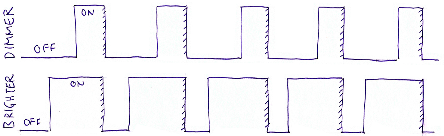
We’ll get many, many shades of grey! (>50 yes!)
And if we apply this nifty trick to each of the RGB LEDs, we’ll get our Full Colour RGB LED!
How shall we program the rapid blinking? Call the GPIO Functions in a loop?
Not a good idea, because our microcontroller will become very busy blinking the LEDs. No time for reading sensors or transmitting data!
Thankfully we have Pulse Width Modulation (PWM)… Our BL602 Microcontroller (and many others) will happily strobe the LED pins for us, without coding any loops.
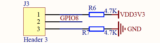
Here’s the schematic for PineCone’s RGB LED…
What are CH1, CH2 and CH4?
CH1, CH2 and CH4 are PWM Channels. Each PWM Channel will let us strobe the output on one pin. (Hence we need 3 PWM Channels)
Let’s match the 3 GPIO Pins and 3 PWM Channels to the Pin Mapping Table: BL602 Reference Manual (Page 27)
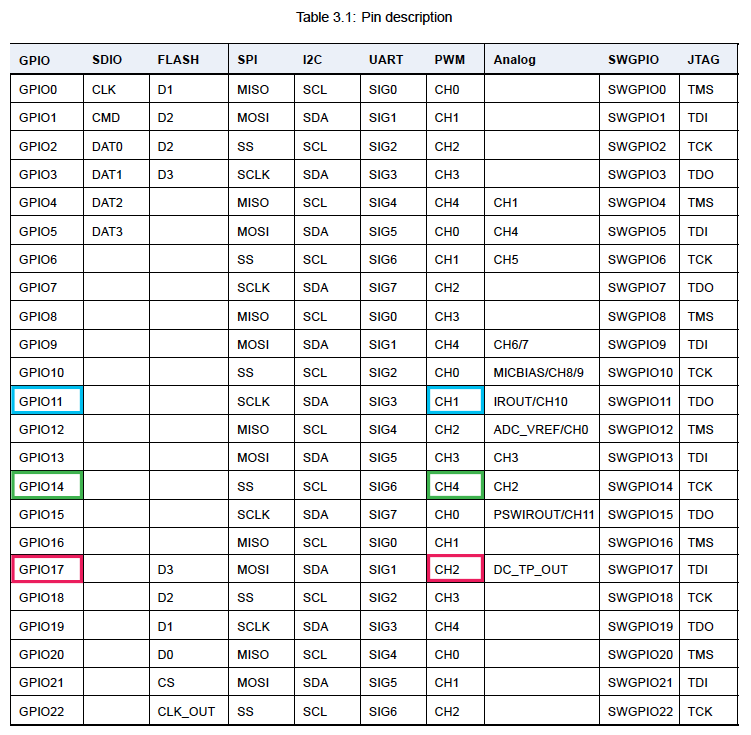
The table says that GPIO 11, 17 and 14 may be mapped to PWM Channels 1, 2 and 4 (by calling the PWM HAL Functions). Perfect!
Remember that we tweaked the spacing of the blinking to get many levels of brightness?
We call this the Duty Cycle in PWM.
Let’s experiment with the RGB LED on PWM…
Now we’ll switch PineCone to the Modified PWM Demo from the BL602 IoT SDK.
(The firmware was modified to run without a Device Tree. More details)
Download the BL602 Demo Firmware Binaries…
Unzip customer_app.zip. Look for the file…
sdk_app_pwm/build_out/sdk_app_pwm.binFlash sdk_app_pwm.bin to PineCone. Follow the instructions in the article…
After flashing, flip the PineCone Jumper (IO 8) to the L Position (Like this)
Press the Reset Button.
Connect to PineCone…
For Linux:
screen /dev/ttyUSB0 2000000For macOS: Use CoolTerm (See this)
For Windows: Use putty (See this)
Alternatively: Use the Web Serial Terminal (See this)
Press the RST Button on PineCone to restart the firmware. Ignore the errors.
Press Enter to reveal the command prompt.
Assign GPIO 11 (Blue), 17 (Red), 14 (Green) to PWM Channels 1, 2 and 4.
Set the PWM Frequency to 2 kHz. (Each LED will blink at 2,000 cycles per second)
pwm_init 1 11 2000
pwm_init 2 17 2000
pwm_init 4 14 2000
Set PWM Duty Cycle for all 3 PWM Channels to 100%.
Which means that 100% of the time, the 3 PWM Channels will be set to 1 (High).
Which means total darkness: All 3 LEDs will be switched off 100% of the time.
pwm_duty_set 1 100
pwm_duty_set 2 100
pwm_duty_set 4 100
Start the PWM Output for all 3 PWM Channels…
pwm_start 1
pwm_start 2
pwm_start 4
Gradually decrease the PWM Duty Cycle for PWM Channel 1 (Blue) from 100% to 0%.
This means the Blue LED will gradually get brighter.
pwm_duty_set 1 75
pwm_duty_set 1 50
pwm_duty_set 1 25
pwm_duty_set 1 0
To exit screen, press Ctrl-A then k then y
Watch the PWM Demo Video on YouTube
Now we look at the BL602 PWM HAL Functions called by the PWM Demo Firmware: sdk_app_pwm.bin
To designate a GPIO PIN as a PWM Channel, we call this PWM HAL Function: bl_pwm.h
int32_t bl_pwm_init(uint8_t id, uint8_t pin, uint32_t freq);id is the PWM Channel ID (0 to 4). BL602 supports 5 PWM Channels: PWM 0 to PWM 4.
pin is the GPIO Pin Number, so pin=0 refers to GPIO 0.
freq is the PWM Frequency (in Hz / Cycles Per Second). So freq=2000 means that the PWM Channel will be blinked 2,000 cycles every second. freq must be between 2,000 and 800,000 (inclusive).
UPDATE: To set the effective PWM Frequency below 2,000 Hz, we may use the PWM Channel Clock Divider (which defaults to 1).
For instance, to achieve a clock frequency of 50 Hz on the PWM, we may set an initial frequency of 6,400 Hz on channel 1, then use…
PWM_Channel_Set_Div(1, 128)Which sets channel 1’s clock divider to 128, making the effective PWM Frequency 50 Hz. (PWM_Channel_Set_Div comes from the PWM Standard Driver)
(Many thanks to Chandler Jearls for the tip!)
Not all GPIO Pins may be assigned to a PWM Channel. Check “Table 3.1: Pin description” (Page 27) in BL602 Reference Manual.
We set the Frequency and Duty Cycle on a PWM Channel by calling these PWM HAL Functions: bl_pwm.h
int32_t bl_pwm_set_freq(uint8_t id, uint32_t freq);
int32_t bl_pwm_set_duty(uint8_t id, float duty);
id is the PWM Channel ID (0 to 4).
freq is the PWM Frequency (in Hz / Cycles Per Second). freq must be between 2,000 and 800,000 (inclusive).
duty is the PWM Duty Cycle (0 to 100). When duty=25, it means that in every PWM Cycle…
To get the Duty Cycle for a PWM Channel, we call this function…
int32_t bl_pwm_get_duty(uint8_t id, float *p_duty);bl_pwm_get_duty stores the Duty Cycle at the pointer passed in p_duty.We start and stop a PWM Channel by calling these PWM HAL Functions: bl_pwm.h
int32_t bl_pwm_start(uint8_t id);
int32_t bl_pwm_stop( uint8_t id);
id is the PWM Channel ID (0 to 4).The above PWM HAL Functions are defined here…
To see the above PWM HAL Functions in action, check out the PWM Demo Source Code…
There is an alternative set of functions for controlling PWM…
These functions are meant to be used with the BL602 Device Tree.
This helpful diagram from the BL602 Reference Manual (Page 158) explains the internals of BL602’s PWM…
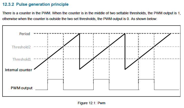
BL602 Pulse Width Modulation
BL602’s PWM uses an Internal Counter to generate a Sawtooth Wave
Each cycle of the Sawtooth Wave has a duration (PWM Period) that’s determined by the PWM Frequency (PWM Period = 1 / PWM Frequency)
The PWM Channel outputs 0 or 1 by comparing the Internal Counter with two values: PWM Threshold1 (the lower limit) and PWM Threshold2 (the upper limit)
We assume that PWM Threshold1 (the lower limit) is always 0. That’s because the BL602 PWM HAL Function bl_pwm_set_duty always sets Threshold1 to 0.
What’s the value of PWM Threshold2 (the upper limit)? That’s computed based on the PWM Period and PWM Duty Cycle: bl_pwm_set_duty
//  The Duty Cycle `duty` is between 0 to 100
threshold2 = ( period / 100 ) * duty;
So when we increase the Duty Cycle, Threshold2 gets higher.
Here’s the PWM Output logic…
When the Internal Counter is below Threshold2, the PWM Channel outputs 1.
And when the Internal Counter is above Threshold2, the PWM Channel outputs 0.
What happens when we increase the Duty Cycle?
Threshold2 gets higher, hence the PWM Channel outputs 1 more often.
That’s precisely the definition of Duty Cycle…
Duty Cycle is the percentage of time (0 to 100) within a Cycle that’s spent Working. (“Working” means Output=1)
Outside of the Duty Cycle, our PWM Channel is Idle. (Output=0)
Note that the Working vs Idle definition is flipped for our LED…
Working (Output=1) switches the LED OFF
Idle (Output=0) switches the LED ON
Which explains this odd behaviour we’ve seen earlier…
Higher Duty Cycle decreases our LED Brightness
Lower Duty Cycle increases our LED Brightness
(Yep the Duty Cycle is Inversely Proportional to the LED Brightness)
Today we have we have explored the GPIO and PWM HAL Functions through the BL602 IoT SDK.
Alternatively we may access BL602 GPIO Functions through another embedded operating system: Apache NuttX…
Stay tuned for more NuttX!
Got a question, comment or suggestion? Create an Issue or submit a Pull Request here…
On macOS, why doesn’t screen work for accessing the BL602 Demo Firmware?
BL602 Demo Firmware configures the UART Port for 2 Mbps. (Which is not a standard POSIX baud rate)
This causes problems for POSIX serial apps (like screen) that don’t call macOS IOKit. See this
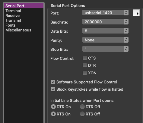
To fix this, use a newer serial app like CoolTerm…
Click Options
Set Port to usbserial-1420
Set Baudrate to 2000000 (2 Mbps)
Click Connect
What if we really really want to use POSIX serial apps like screen?
This is NOT recommended… But to support POSIX serial apps with macOS, we need to lower the UART baud rate from 2 Mbps to 230.4 kbps. (Which is a POSIX baud rate)
In the BL602 Demo Firmware, edit the main.c source file, like…
Look for this line that configures the UART port for 2 Mbps…
bl_uart_init(0, 16, 7, 255, 255, 2 * 1000 * 1000);Change it to 230.4 kbps…
bl_uart_init(0, 16, 7, 255, 255, 230400);Rebuild the firmware.
Edit the BL602 Device Tree: bl_factory_params_IoTKitA_40M.dts
Look for…
uart {
    #address-cells = <1>;
    #size-cells = <1>;
    uart@4000A000 {
        status = "okay";
        id = <0>;
        compatible = "bl602_uart";
        path = "/dev/ttyS0";
        baudrate = <2000000>;
Change baudrate to…
baudrate = <230400>;Compile the Device Tree with BLOpenFlasher.
Copy the compiled Device Tree ro_params.dtb to blflash
Flash the firmware to PineCone with blflash
After flashing, set the PineCone Jumper IO8 to L Position. Press the Reset Button.
We should be able to access the Demo Firmware at 230.4 kbps…
screen /dev/tty.usbserial-1420 230400 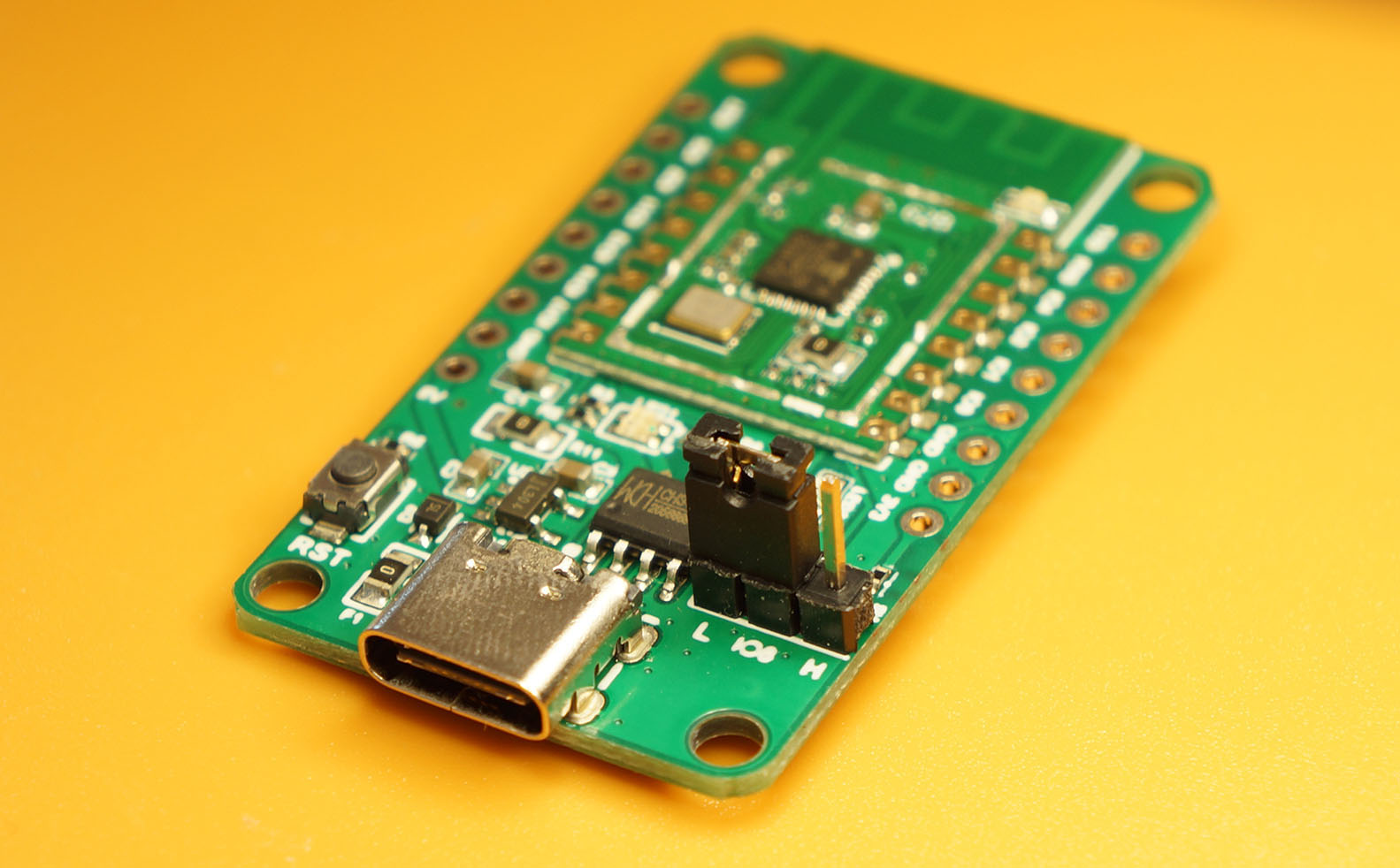