📝 19 Feb 2021
Today we shall connect PineCone BL602 RISC-V Board to the Grove Triple Color E-Ink Display 2.13“ with UART Interface.
The Demo Firmware in this article will run on PineCone, Pinenut and Any BL602 Board.
It’s 2021… Why are we learning UART?
UART has been around since 1960… Before I was born!
Many modern peripherals expose UART as a “Managed Interface” instead of the raw underlying interface (like SPI)…
UART coding is simpler than SPI and I2C.
(Though UART is not recommended for transmitting and receiving data at high speeds… Data may get dropped when there’s no hardware flow control)
UART is still used by all kinds of peripherals: GPS Receivers, E-Ink Displays, LoRa Transceivers, …
(UART is probably OK for E-Ink Displays because we’re pushing pixels at a leisurely bitrate of 230.4 kbps … And we don’t need to receive much data from the display)
This article shall be Your Best Friend if you ever need to connect BL602 to a UART Peripheral.
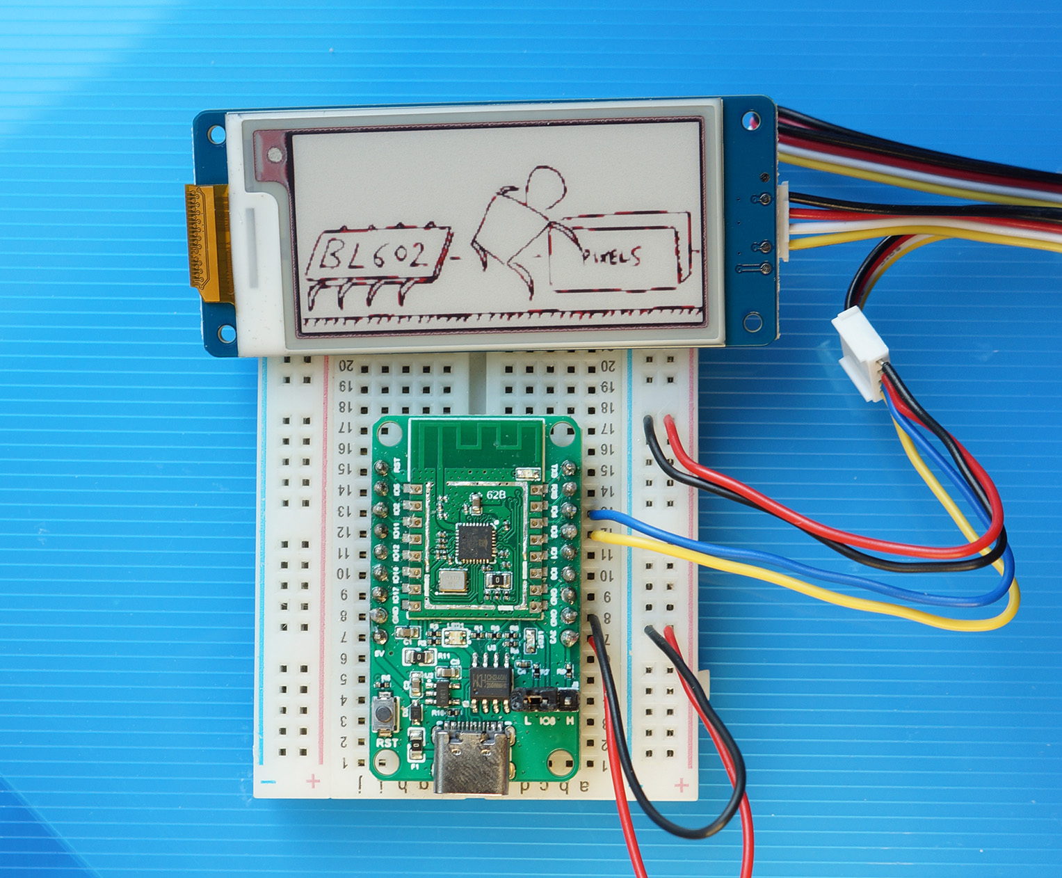
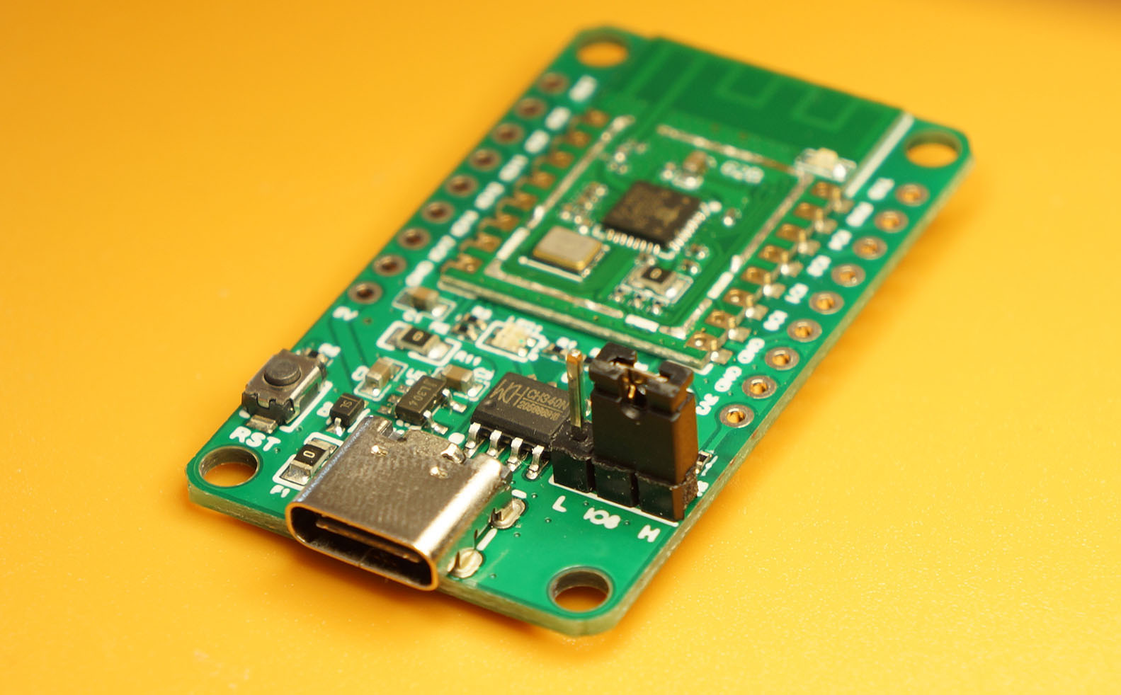
PineCone BL602 RISC-V Board rendering an image on Grove Triple Colour E-Ink Display with UART Interface
The BL602 IoT SDK contains a UART Hardware Abstraction Layer (HAL) that we may call in our C programs to access the two UART Ports.
BL602’s UART HAL is packaged as two levels…
Low Level HAL bl_uart.c: This runs on BL602 Bare Metal.
The Low Level HAL manipulates the BL602 UART Registers directly to perform UART functions.
High Level HAL hal_uart.c: This calls the Low Level HAL, and uses the Device Tree and FreeRTOS.
The High Level HAL is called by the AliOS Firmware created by the BL602 IoT SDK.
(AliOS functions are easy to identify… Their function names begin with “aos_”)
Today we shall use the Low Level UART HAL bl_uart.c because…
The Low Level UART HAL is simpler to understand.
We’ll learn all about the BL602 UART Hardware by calling the Low Level HAL Functions.
(No Device Tree, no AliOS)
The Low Level UART HAL works on all Embedded Operating Systems.
(Not just FreeRTOS)
We shall call the BL602 Low Level UART HAL to control the Grove E-Ink Display with this BL602 Command-Line Firmware: sdk_app_uart_eink
The firmware will work on all BL602 boards, including PineCone and Pinenut.
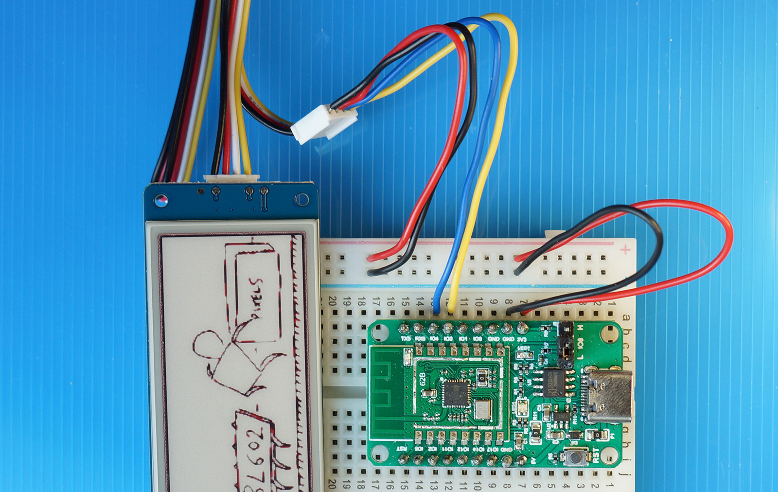
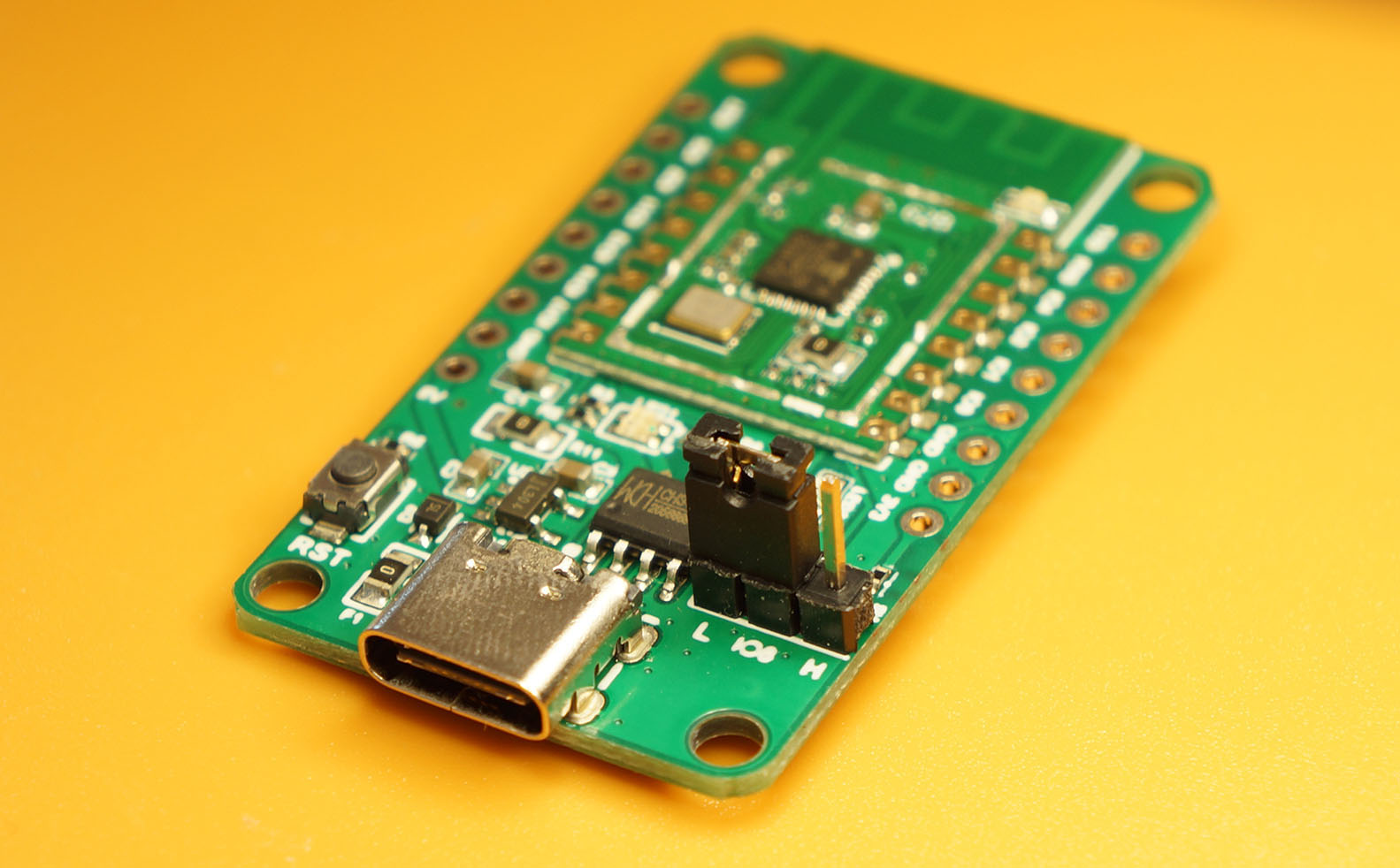
PineCone BL602 connected to Grove E-Ink Display
Connect BL602 to Grove E-Ink Display according to the pic above…
| BL602 Pin | E-Ink Display | Wire Colour |
|---|---|---|
GPIO 3 | TX | Yellow |
GPIO 4 | RX | Blue / White |
3V3 | 3.3V | Red |
GND | GND | Black |
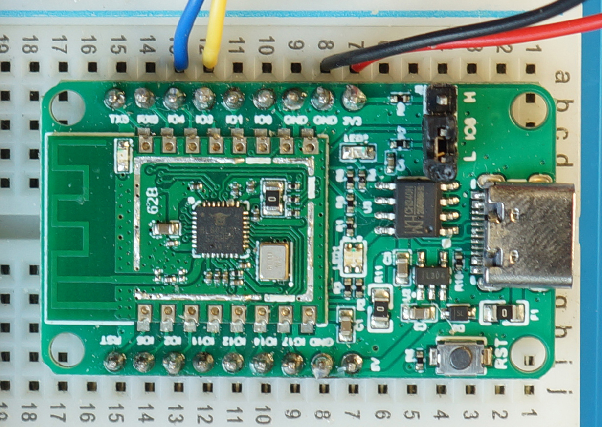
Here’s an extreme closeup of the PineCone BL602 pins…
The screen works without power! What magic is this?
Remember that E-Ink Displays only need power when we’re updating the display.
Which makes them very useful for Low Power IoT Gadgets.
(But we’re not supposed to update the screen too often)
Let’s dive into the code for our Demo Firmware!
We initialise the UART Port like so: demo.c
/// Use UART Port 1 (UART Port 0 is reserved for console)
#define UART_PORT 1

/// Command to display image
static void display_image(char *buf, int len, int argc, char **argv) {
    ...
    //  Init UART Port 1 with Tx Pin 4, Rx Pin 3 at 230.4 kbps
    int rc = bl_uart_init(
        UART_PORT,  //  UART Port 1
        4,          //  Tx Pin (Blue)
        3,          //  Rx Pin (Yellow)
        255,        //  CTS Unused
        255,        //  RTS Unused
        230400      //  Baud Rate
    );
    assert(rc == 0);
Here we define display_image, the command that we’ll be running in our Demo Firmware.
It calls bl_uart_init (from BL602 Low Level UART HAL) to initialise the UART Port with these parameters…
UART Port: We select UART Port 1.
BL602 has 2 UART Ports: 0 and 1.
UART Port 0 is reserved for the Command-Line Interface, so we should always use UART Port 1.
Transmit Pin: We select Pin 4, as recommended by the BL602 Device Tree.
(For valid pins, check the BL602 Reference Manual, Table 3.1 “Pin Description”, Page 27)
Receive Pin: We select Pin 3, as recommended by the BL602 Device Tree.
CTS Pin: We set this to 255 because we’re not using Hardware Flow Control.
RTS Pin: We set this to 255 because we’re not using Hardware Flow Control.
Baud Rate: We set this to 230400 bps (or 230.4 kbps), as specified in the Grove E-Ink Docs.
Maximum baud rate is 10 Mbps.
We’ll come back to display_image in a while. First let’s learn to transmit and receive some UART data.
Before we send a bitmap to the E-Ink Display for rendering, we do a Start Transfer Handshake to make sure that everybody’s all ready…
We wait until we receive the character 'c' from the E-Ink Display
We transmit the character 'a' to the E-Ink Display
Finally we wait until we receive the character 'b' from the E-Ink Display
Let’s implement this with the BL602 Low Level UART HAL.
Here’s how we receive one byte of data from the UART Port…
//  Use UART Port 1 (UART Port 0 is reserved for console)
#define UART_PORT 1

//  Read one byte from UART Port 1, returns -1 if nothing read
int ch = bl_uart_data_recv(UART_PORT);
Note that bl_uart_data_recv (from the BL602 Low Level UART HAL) returns -1 if there’s no data to be read.
Thus we usually call bl_uart_data_recv in a loop like so: demo.c
/// Do the Start Transfer Handshake with E-Ink Display:
/// Receive 'c', send 'a', receive 'b'
void send_begin() {
    //  Wait until 'c' is received
    for (;;) {
        //  Read one byte from UART Port, returns -1 if nothing read
        int ch = bl_uart_data_recv(UART_PORT);
        if (ch < 0) { continue; }  //  Loop until we receive something

        //  Stop when we receive 'c'
        if (ch == 'c') { break; }
    }
Here we define the function send_begin that performs the Start Transfer Handshake.
This code loops until the character 'c' has been received from the UART Port. Which is the First Step of our handshake.
Second Step of the handshake: Send the character 'a'…
    //  Send 'a'
    int rc = bl_uart_data_send(UART_PORT, 'a');
    assert(rc == 0);
Here we call bl_uart_data_send (also from the BL602 Low Level UART HAL) to transmit the character 'a' to the UART Port.
Finally the Third Step: Wait until 'b' has been received from the UART Port…
    //  Wait until 'b' is received
    for (;;) {
        //  Read one byte from UART Port, returns -1 if nothing read
        int ch = bl_uart_data_recv(UART_PORT);
        if (ch < 0) { continue; }  //  Loop until we receive something

        //  Stop when we receive 'b'
        if (ch == 'b') { break; }
    }
}
(Looks very similar to the First Step)
And we’re done with the Start Transfer Handshake!
Note that we’re polling the UART Port, which is OK because we’re mostly transmitting data, and receiving little data.
If we’re receiving lots of data through polling, we might lose some data. For such cases, we should use UART Interrupts or DMA.
(The E-Ink Display code in this article was ported from Arduino to BL602. See this)
Let’s head back to display_image, the function in our Demo Firmware that controls the E-Ink Display to render an image: demo.c
/// Command to display image
static void display_image(char *buf, int len, int argc, char **argv) {
    ...
    //  Init UART Port 1 with Tx Pin 4, Rx Pin 3 at 230.4 kbps
    int rc = bl_uart_init( ... );  //  Omitted, we have seen this earlier
    assert(rc == 0);

    //  Sleep for 10 milliseconds
    vTaskDelay(10 / portTICK_PERIOD_MS);
We’ve initialised the UART Port with bl_uart_init (as seen earlier).
To give the E-Ink Display a bit of time to get ready, we call vTaskDelay (from FreeRTOS) to sleep for 10 milliseconds.
    //  Do the Start Transfer Handshake with E-Ink Display
    send_begin();

    //  Sleep for 2 seconds (2000 milliseconds)
    vTaskDelay(2000 / portTICK_PERIOD_MS);
Then we call send_begin to do the Start Transfer Handshake (from the previous section).
We give the E-Ink Display a little more pondering time, by calling vTaskDelay to sleep for 2 seconds.
    //  Send the display data
    write_image_picture();
}
At the end of the function, we call write_image_picture to send the image data.
Let’s look inside write_image_picture
To display a image on our E-Ink Display, we shall transmit two bitmaps: Black Bitmap and Red Bitmap.
(More about the Black and Red Bitmaps in a while)
From demo.c
/// Send Black and Red Image Data to display
static void write_image_picture(void) {
    //  Send Black Pixels to display in 13 chunks of 212 bytes
    for (int i = 0; i < 13; i++) {
        //  Send a chunk of 212 bytes
        send_data(&IMAGE_BLACK[0 + i * 212], 212);

        //  Sleep for 80 milliseconds
        vTaskDelay(80 / portTICK_PERIOD_MS);
    }
Here we define the function write_image_picture that will transmit the two bitmaps to our E-Ink Display.
We start with the Black Bitmap IMAGE_BLACK, calling send_data to transmit 13 chunks of 212 bytes each.
(We’ll see send_data in a while)
Then we give our E-Ink Display display a short rest…
    //  Sleep for 90 milliseconds
    vTaskDelay(90 / portTICK_PERIOD_MS);
And we transmit the Red Bitmap IMAGE_RED the same way…
    //  Send Red Pixels to display in 13 chunks of 212 bytes
    for (int i = 0; i < 13; i++) {
        //  Send a chunk of 212 bytes
        send_data(&IMAGE_RED[0 + i * 212], 212);

        //  Sleep for 80 milliseconds
        vTaskDelay(80 / portTICK_PERIOD_MS);
    }
}
In send_data we transmit a chunk of data to our E-Ink Display like so: demo.c
/// Send data to display over UART. data_len is number of bytes.
static void send_data(const uint8_t* data, uint32_t data_len) {
    for (int i = 0; i < data_len; i++) {
        int rc = bl_uart_data_send(UART_PORT, data[i]);
        assert(rc == 0);
    }
}
send_data calls bl_uart_data_send (from BL602 Low Level UART HAL) to transmit the data to the UART Port, one byte at a time.
(We’ve seen this earlier during the handshake)
That’s all for the UART code that talks to the E-Ink Display!
Let’s run the E-Ink Display UART Demo Firmware for BL602.
Download the Firmware Binary File sdk_app_uart_eink.bin from…
Alternatively, we may build the Firmware Binary File sdk_app_uart_eink.bin from the source code…
## Download the master branch of lupyuen's bl_iot_sdk
git clone --recursive --branch master https://github.com/lupyuen/bl_iot_sdk
cd bl_iot_sdk/customer_app/sdk_app_uart_eink

## TODO: Change this to the full path of bl_iot_sdk
export BL60X_SDK_PATH=$HOME/bl_iot_sdk
export CONFIG_CHIP_NAME=BL602
make

## For WSL: Copy the firmware to /mnt/c/blflash, which refers to c:\blflash in Windows
mkdir /mnt/c/blflash
cp build_out/sdk_app_uart_eink.bin /mnt/c/blflash
More details on building bl_iot_sdk
Follow these steps to install blflash…
We assume that our Firmware Binary File sdk_app_st7789.bin has been copied to the blflash folder.
Set BL602 to Flashing Mode and restart the board.
For PineCone:
Set the PineCone Jumper (IO 8) to the H Position (Like this)
Press the Reset Button
For BL10:
Connect BL10 to the USB port
Press and hold the D8 Button (GPIO 8)
Press and release the EN Button (Reset)
Release the D8 Button
For Ai-Thinker Ai-WB2, Pinenut and MagicHome BL602:
Disconnect the board from the USB Port
Connect GPIO 8 to 3.3V
Reconnect the board to the USB port
Enter these commands to flash sdk_app_uart_eink.bin to BL602 over UART…
## For Linux:
blflash flash build_out/sdk_app_uart_eink.bin \
    --port /dev/ttyUSB0

## For macOS:
blflash flash build_out/sdk_app_uart_eink.bin \
    --port /dev/tty.usbserial-1420 \
    --initial-baud-rate 230400 \
    --baud-rate 230400

## For Windows: Change COM5 to the BL602 Serial Port
blflash flash c:\blflash\sdk_app_uart_eink.bin --port COM5
(For WSL: Do this under plain old Windows CMD, not WSL, because blflash needs to access the COM port)
More details on flashing firmware
Set BL602 to Normal Mode (Non-Flashing) and restart the board…
For PineCone:
Set the PineCone Jumper (IO 8) to the L Position (Like this)
Press the Reset Button
For BL10:
For Ai-Thinker Ai-WB2, Pinenut and MagicHome BL602:
Disconnect the board from the USB Port
Connect GPIO 8 to GND
Reconnect the board to the USB port
After restarting, connect to BL602’s UART Port at 2 Mbps like so…
For Linux:
screen /dev/ttyUSB0 2000000For macOS: Use CoolTerm (See this)
For Windows: Use putty (See this)
Alternatively: Use the Web Serial Terminal (See this)
More details on connecting to BL602
Press the Reset Button.
We should see BL602 starting our firmware…
## ▒Starting bl602 now....
Booting BL602 Chip...
██████╗ ██╗      ██████╗  ██████╗ ██████╗
██╔══██╗██║     ██╔════╝ ██╔═████╗╚════██╗
██████╔╝██║     ███████╗ ██║██╔██║ █████╔╝
██╔══██╗██║     ██╔═══██╗████╔╝██║██╔═══╝
██████╔╝███████╗╚██████╔╝╚██████╔╝███████╗
╚═════╝ ╚══════╝ ╚═════╝  ╚═════╝ ╚══════╝

------------------------------------------------------------
RISC-V Core Feature:RV32-ACFIMX
Build Version: release_bl_iot_sdk_1.6.11-1-g66bb28da-dirty
Build Date: Feb 17 2021
Build Time: 19:06:40
-----------------------------------------------------------

blog init set power on level 2, 2, 2.
[IRQ] Clearing and Disable all the pending IRQ...
[OS] Starting aos_loop_proc task...
[OS] Starting OS Scheduler...
Init CLI with event Driven
Press Enter to reveal the command prompt.
Enter help to see the available commands…
help
====Build-in Commands====
====Support 4 cmds once, seperate by ; ====
help                     : print this
p                        : print memory
m                        : modify memory
echo                     : echo for command
exit                     : close CLI
devname                  : print device name
sysver                   : system version
reboot                   : reboot system
poweroff                 : poweroff system
reset                    : system reset
time                     : system time
ota                      : system ota
ps                       : thread dump
ls                       : file list
hexdump                  : dump file
cat                      : cat file

====User Commands====
display_image            : Display image
blogset                  : blog pri set level
blogdump                 : blog info dump
bl_sys_time_now          : sys time now
Enter display_image to render an image on our E-Ink Display.
(This executes the display_image function that we’ve seen earlier)
We should see this…
display_image
Doing start transfer handshake...
0x9d 0xbe 0x9f 0xbe 0xe8 0xcd 0x9e 0xad 0xea 0x2a 0x3a 0xf8
Received 'c'
Sent 'a'
0x63
Received 'b'
Start transfer handshake OK
Here we see that our display_image function has completed the handshake.
(If the handshake hangs, disconnect BL602 our computer’s USB port, reconnect it and run the firmware again.)
Then our display_image function sends the black and red bitmaps over the UART Port…
Sending black pixels...
Sending red pixels...
The image appears on the display, like the pic below.
Note that the Grove E-Ink Display will flash some graphics when it is powered on…
This seems to be triggered by the STM32 F031 Microcontroller that’s inside the Grove E-Ink Display. (See the schematics)
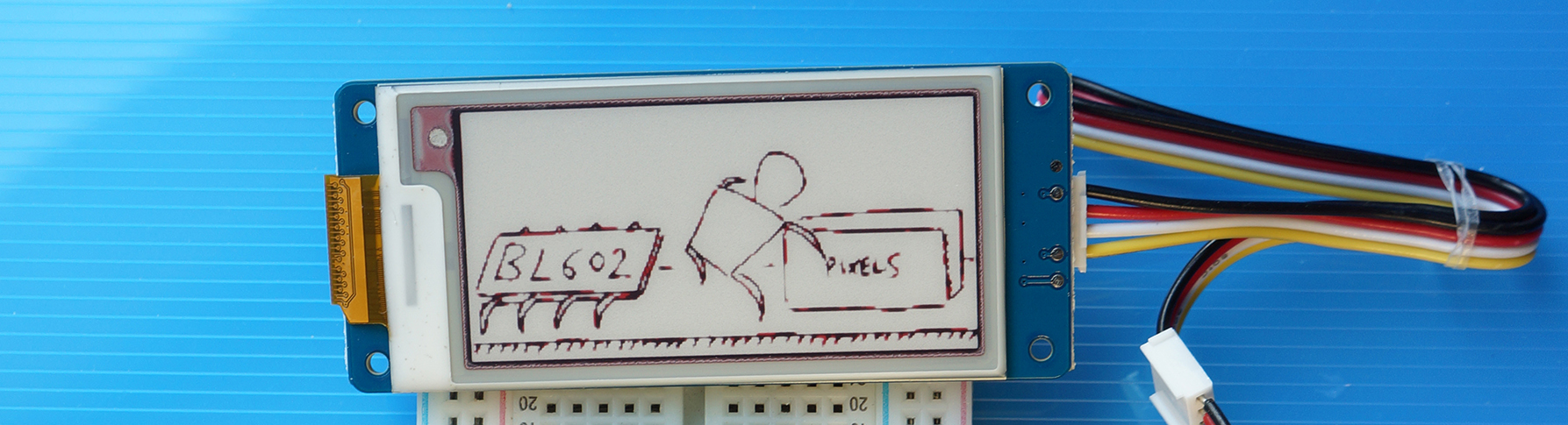
Grove E-Ink Display close up
That’s not a plain black and white image right? I see some red fringes…
The E-Ink Display is actually showing a black, white AND red image!
We can’t show Fifty Shades of Grey on our display… But we can use Red as a Single Shade of Grey!
Our E-Ink Display is capable of rendering two separate bitmaps: black and red.
(Any pixel that’s not flipped on in the black and red bitmaps will appear as white… Thus it’s a Triple Colour Display)
Here’s how we define the black and red bitmaps in our firmware: demo.c
/// Define the Black Pixels of the image
const unsigned char IMAGE_BLACK[] = {
    #include "image_black.inc"
};

/// Define the Red Pixels of the image
const unsigned char IMAGE_RED[] = {
    #include "image_red.inc"
};
A peek into the black bitmap reveals this: image_black.inc
//  Min: 0, Max: 85
//  Rows: 104, Columns: 212
0xff, 0xff, 0xff, 0xff, 0xff, 0xff, 0xff, 0xff, 0xff, 0xff, 0xff, 0xff, 0x3f, 0xff, 0xff, 0xff,
0xff, 0xff, 0xff, 0xff, 0xff, 0xdf, 0xff, 0xff, 0xff, 0x1f, 0xff, 0xff, 0xff, 0xff, 0xff, 0xff,
...
(That’s 2,756 bytes: 104 rows * 212 columns * 1 bit per pixel)
And for the red bitmap: image_red.inc
//  Min: 86, Max: 215
//  Rows: 104, Columns: 212
0xff, 0xff, 0xff, 0xff, 0xff, 0xff, 0xff, 0xff, 0xff, 0xff, 0xff, 0xff, 0xff, 0xff, 0xff, 0xff,
0xff, 0xff, 0xff, 0xff, 0xff, 0xef, 0xff, 0xff, 0xff, 0xff, 0xff, 0xff, 0xff, 0xff, 0xff, 0xff,
...
(Also 2,756 bytes)
What are Min and Max?
The black and red bitmaps were generated from a Greyscale PNG file: uart-cartoon2.png
Min and Max are the Threshold RGB Values used to generate each bitmap…
Black Bitmap contains pixels whose original RGB values range from 0 to 85 (close to black)
Red Bitmap contains pixels whose original RGB values range from 86 to 215 (between black and white)
Here’s how we convert the PNG file uart-cartoon2.png (202 x 104 resolution) to the C arrays image_black.inc (black bitmap) and image_red.inc (red bitmap)..
## Download the source code
git clone https://github.com/lupyuen/pinetime-graphic
cd pinetime-graphic

## TODO: Copy uart-cartoon2.png to the pinetime-graphic folder

## Convert the PNG file to a C array (black bitmap) with these min and max thresholds
cargo run -- --min 0  --max 85  uart-cartoon2.png >image_black.inc

## Convert the PNG file to a C array (red bitmap) with these min and max thresholds
cargo run -- --min 86 --max 215 uart-cartoon2.png >image_red.incExciting things coming up…
LoRa on BL602: We shall connect Semtech SX1276 to BL602 to achieve Triple Wireless Connectivity… WiFi, Bluetooth LE AND LoRa!
(Many thanks to RAKwireless for providing a LoRa Node for our BL602 experiments!)
BL602 for Education: We shall create more Open-Source Educational Content to make BL602 (and RISC-V) fully accessible to learners around the world.
Hopefully someday we’ll see a Deconstructed PineTime Smartwatch: BL602 (RISC-V, WiFi, Bluetooth LE, LoRa) plus the sensors, actuators and display from a smartwatch… Connected on a Breadboard for easy coding!
Meanwhile there’s plenty more code in the BL602 IoT SDK to be deciphered and documented: ADC, DAC, WiFi, Bluetooth LE, …
Come Join Us… Make BL602 Better!
🙏 👍 😀
Got a question, comment or suggestion? Create an Issue or submit a Pull Request here…
This article is the expanded version of this Twitter Thread
Would be great if we could have the STM32 Source Code for the Grove E-Ink Display. (See this issue)