Enhanced MCUBoot Bootloader running on PineTime Smart Watch
📝 18 May 2020
Today we'll talk about the Enhanced MCUBoot Bootloader for PineTime Smart Watch.
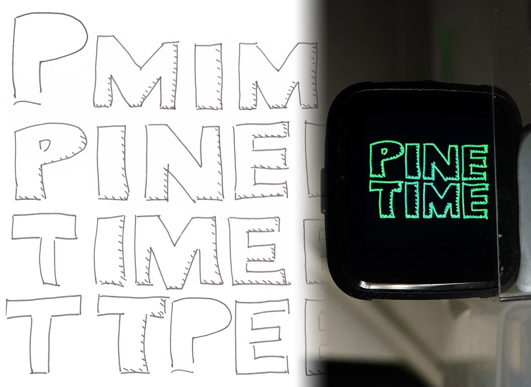
Here's a sneak peek of the Enhanced MCUBoot Bootloader running on PineTime...
We'll learn how the open-source MCUBoot Bootloader (covered in an earlier article) has been enhanced to support...
SPI Flash for storing the Standby Firmware Image
Rendering the Boot Graphic that's stored in SPI Flash
(Because PineTime Owners should have the freedom to customise the way it looks!)
Manual Firmware Rollback when the watch button is pressed during startup
...Without making any code changes to MCUBoot! (Amazing!)
We'll see that the enhancements to MCUBoot were done through configuration files, and by adding some new functions.
Isn't it easier to fork MCUBoot and change the code?
We shall always resist the temptation to modify MCUBoot code... Because MCUBoot is a Critical and Secure part of PineTime!
MCUBoot must not be allowed to crash or hang due to buggy code.
MCUBoot is the first thing that runs when PineTime starts up. If MCUBoot crashes or hangs, PineTime Owners will have a bricked watch on their wrists.
MCUBoot is designed to start firmware securely, protected by digital signatures.
Although we don't secure PineTime firmware today, MCUBoot may someday be used to verify that our firmware hasn't been tampered with.
(Because the data collected by our smart watches may be misused to harm us someday)
If you haven't read the earlier article on MCUBoot... Please do so now!
Our earlier design for MCUBoot hit a showstopper... The Application Firmware size was limited to 232 KB, which is too small acccording to PineTime Firmware Developers.
With Enhanced MCUBoot, we can now support firmware twice that size... Up to 464 KB! (Remember that PineTime's Flash ROM is only 512 KB)
How did we get so much ROM space?
We moved the Standby Firmware Image from PineTime's Flash ROM (512 KB) to PineTime's SPI Flash (4 MB).
During firmware update, the Standby Firmware slot is used as the staging area for the new firmware. On reboot, MCUBoot swaps the new firmware with the old firmware. If the new firmware doesn't start properly, MCUBoot swaps them back.
Here's the updated Flash Memory Map for PineTime. Note that the Standby Firmware Image is now stored in Flash Device 1 (SPI Flash) instead of Flash Device 0 (Internal ROM): hw/bsp/nrf52/bsp.yml
# Flash Memory Map for PineTime: Internal Flash ROM and External SPI Flash
bsp.flash_map:
    areas:
        # System areas.
        FLASH_AREA_BOOTLOADER:       # MCUBoot
            device:  0               # Internal Flash ROM
            offset:  0x00000000      # Start of Internal Flash ROM
            size:    28kB
        FLASH_AREA_IMAGE_0:          # Active Firmware Image
            device:  0               # Internal Flash ROM
            offset:  0x00008000
            size:    464kB           # Max size of Firmware Image
        FLASH_AREA_IMAGE_1:          # Standby Firmware Image
            device:  1               # External SPI Flash
            offset:  0x00040000
            size:    464kB           # Max size of Firmware Image
        FLASH_AREA_IMAGE_SCRATCH:    # Used by MCUBoot for swapping Active and Standby Firmware
            device:  0               # Internal Flash ROM
            offset:  0x0007c000
            size:    4kB

        # User areas.
        FLASH_AREA_REBOOT_LOG:       # For logging debug messages during startup
            user_id: 0
            device:  0               # Internal Flash ROM
            offset:  0x00007000      # Note: 0x7f00-0x7fff contains the relocated vector table
            size:    4kB
        # FLASH_AREA_BOOTLOADER_ASSET: # Bootloader Assets, like Boot Graphic
        #   user_id: 1
        #   device:  1               # External SPI Flash
        #   offset:  0x00000000      # Start of External SPI Flash
        #   size:    256kB
        FLASH_AREA_NFFS:             # For user files
            user_id: 1
            device:  1               # External SPI Flash
            offset:  0x000b4000
            size:    3376kB
TODO: 0x7f00 to 0x7fff is reserved for the relocated Vector Table. Active and Standby Firmware Images should be extended by 12 KB. Scratch Area and User File System should be moved down by 12 KB.
More about PineTime's SPI Flash
Here's the layout for PineTime's Flash ROM...
| Flash ROM Area | Address | Size |
|---|---|---|
| Bootloader (MCUBoot) | 0x0000 0000 | 28 KB |
| Reboot Log | 0x0000 7000 | 4 KB |
| Active Firmware Image | 0x0000 8000 | 464 KB |
| Scratch Area | 0x0007 C000 | 4 KB |
TODO: 0x7f00 to 0x7fff is reserved for the relocated Vector Table. Active Firmware Image should be extended by 12 KB. Scratch Area should be moved down by 12 KB
And the layout for PineTime's SPI Flash...
| SPI Flash Area | Address | Size |
|---|---|---|
| Bootloader Assets | 0x0000 0000 | 256 KB |
| Standby Firmware Image | 0x0004 0000 | 464 KB |
| User File System | 0x000B 4000 | 3,376 KB |
TODO: Standby Firmware Image should be extended by 12 KB. User File System should be moved down by 12 KB
The User File System has been bumped up to a whopping 3.2 MB (from 12 KB).
PineTime Watch Apps may store graphical assets and other app data in the User File System, once we install a Flash File System like littlefs.
Supporting littlefs on PineTime
Bootloader Assets (256 KB) is a new flash area in SPI Flash. What's inside?
The Enhanced MCUBoot Bootloader now renders a Boot Graphic that's 112.5 KB in size. The Boot Graphic is stored in the Bootloader Assets flash area.
Half of the Bootloader Assets area is unused. We expect to use the free space to store fonts and other graphical assets that will be rendered by Enhanced MCUBoot.
The Bootloader Assets area doesn't use any Flash File System (like littlefs). We'll learn why in a while.
Why is Bootloader Assets commented out in the Flash Memory Map hw/bsp/nrf52/bsp.yml?
The Mynewt build fails when it encounters a custom flash area (like Bootloader Assets) in the Flash Memory Map. So it has been commented out.
But the SPI Flash space has been budgeted correctly, so that none of the other flash areas will overlap with Bootloader Assets.
Let's discover how PineTime's ST7789 Display Controller renders graphics...
Watch how Enhanced MCUBoot renders the Boot Graphic (hand-drawn PineTime logo) before starting the Application Firmware ("I AM PINETIME")...
Enhanced MCUBoot needs to render the Boot Graphic the quickest and most reliable way possible because...
PineTime Owners will see this every time PineTime powers on, so it must be quick
The rendering must not crash MCUBoot, even when SPI Flash is corrupted
(Yes the Boot Graphic may look really awful, but PineTime must always boot!)
And the rendering needs to be done within the 24 KB of code space allocated to Enhanced MCUBoot
(Which means we'll have to make assumptions and hard code certain things)
Let's read the code in Enhanced MCUBoot and understand how it renders the Boot Graphic quickly and reliably: display.c
#define DISPLAY_CS   25  //  GPIO Pin 25 for LCD_CS (P0.25): Chip select
#define DISPLAY_DC   18  //  GPIO Pin 18 for LCD_RS (P0.18): Clock/data pin (CD)
#define DISPLAY_RST  26  //  GPIO Pin 26 for LCD_RESET (P0.26): Display reset
#define DISPLAY_HIGH 23  //  GPIO Pin 23 for LCD_BACKLIGHT_HIGH (23): High backlight (active low)

/// Initialise the ST7789 display controller
static int init_display(void) {
    //  Assume that SPI port 0 has been initialised by the SPI Flash Driver at startup.
    hal_gpio_init_out(DISPLAY_RST, 1);  //  Configure GPIO Pin for output
    hal_gpio_init_out(DISPLAY_CS, 1);
    hal_gpio_init_out(DISPLAY_DC, 0);
    hal_gpio_init_out(DISPLAY_HIGH, 0);  //  Switch on backlight

    hard_reset();  //  Reset the display controller by toggling the Reset GPIO Pin
    write_command(SWRESET, NULL, 0); delay_ms(200);  //  Write a command and delay for 200 milliseconds
    write_command(SLPOUT, NULL, 0); delay_ms(200);

    static const uint8_t FRMCTR1_PARA[] = { 0x01, 0x2C, 0x2D };
    write_command(FRMCTR1, FRMCTR1_PARA, sizeof(FRMCTR1_PARA));

    static const uint8_t FRMCTR2_PARA[] = { 0x01, 0x2C, 0x2D };
    write_command(FRMCTR2, FRMCTR2_PARA, sizeof(FRMCTR2_PARA));

    static const uint8_t FRMCTR3_PARA[] = { 0x01, 0x2C, 0x2D, 0x01, 0x2C, 0x2D };
    write_command(FRMCTR3, FRMCTR3_PARA, sizeof(FRMCTR3_PARA));

    static const uint8_t INVCTR_PARA[] = { 0x07 };
    write_command(INVCTR, INVCTR_PARA, sizeof(INVCTR_PARA));

    static const uint8_t PWCTR1_PARA[] = { 0xA2, 0x02, 0x84 };
    write_command(PWCTR1, PWCTR1_PARA, sizeof(PWCTR1_PARA));

    static const uint8_t PWCTR2_PARA[] = { 0xC5 };
    write_command(PWCTR2, PWCTR2_PARA, sizeof(PWCTR2_PARA));

    static const uint8_t PWCTR3_PARA[] = { 0x0A, 0x00 };
    write_command(PWCTR3, PWCTR3_PARA, sizeof(PWCTR3_PARA));

    static const uint8_t PWCTR4_PARA[] = { 0x8A, 0x2A };
    write_command(PWCTR4, PWCTR4_PARA, sizeof(PWCTR4_PARA));

    static const uint8_t PWCTR5_PARA[] = { 0x8A, 0xEE };
    write_command(PWCTR5, PWCTR5_PARA, sizeof(PWCTR5_PARA));

    static const uint8_t VMCTR1_PARA[] = { 0x0E };
    write_command(VMCTR1, VMCTR1_PARA, sizeof(VMCTR1_PARA));

    write_command(INVON, NULL, 0);

    static const uint8_t MADCTL1_PARA[] = { 0x00 };
    write_command(MADCTL, MADCTL1_PARA, sizeof(MADCTL1_PARA));

    static const uint8_t COLMOD_PARA[] = { 0x05 };
    write_command(COLMOD, COLMOD_PARA, sizeof(COLMOD_PARA));

    write_command(DISPON, NULL, 0); delay_ms(200);
    return 0;
}
Here's the code in display.c that initialises the Sitronix ST7789 Display Controller for PineTime's 240 x 240 Colour LCD Screen.
At startup, the function above sends a bunch of commands and parameters to the ST7789 Display Controller via the SPI port. We send commands and data (parameters) to ST7789 in a peculiar way in display.c...
#define DISPLAY_SPI   0  //  ST7789 connected to SPI port 0
#define DISPLAY_DC   18  //  GPIO Pin 18 for LCD_RS (P0.18): Clock/data pin (CD)
#define DISPLAY_CS   25  //  GPIO Pin 25 for LCD_CS (P0.25): Chip select

/// Transmit ST7789 command
static int write_command(uint8_t command, const uint8_t *params, uint16_t len) {
    hal_gpio_write(DISPLAY_DC, 0);  //  Enter Command Mode
    transmit_spi(&command, 1);
    if (params != NULL && len > 0) { write_data(params, len); }
    return 0;
}

/// Transmit ST7789 data
static int write_data(const uint8_t *data, uint16_t len) {
    hal_gpio_write(DISPLAY_DC, 1);  //  Enter Data Mode
    transmit_spi(data, len);
    return 0;
}

/// Write to the SPI port
static int transmit_spi(const uint8_t *data, uint16_t len) {
    hal_gpio_write(DISPLAY_CS, 0);     //  Select the display controller
    int rc = hal_spi_txrx(DISPLAY_SPI, //  Send to SPI port...
        (void *) data,                 //  Transmit Buffer
        NULL,                          //  Receive Buffer (NULL means don't receive)
        len);                          //  Length
    hal_gpio_write(DISPLAY_CS, 1);     //  De-select the display controller
    return 0;
}
We toggle GPIO Pin 18 (DISPLAY_DC) to tell ST7789 whether we are sending a Command Byte or a sequence of Data Bytes. So in this example...
static const uint8_t FRMCTR1_PARA[] = { 0x01, 0x2C, 0x2D };
write_command(FRMCTR1, FRMCTR1_PARA, sizeof(FRMCTR1_PARA));
We set GPIO Pin 18 to Low to transmit the FRMCTR1 Command Byte 0xB1
Then set GPIO Pin 18 to High to transmit the Data Bytes 0x01, 0x2C, 0x2D
Yes it's unusual, cumbersome and limits SPI performance. It was probably done to force-fit a 4-Line Serial Interface into the 3-Line SPI Interface.
Note: The above initialisation commands and parameters don't quite match up with the ST7789 datasheet. That's because the code was originally written for the ST7735 Display Controller. This should be fixed, but it works on PineTime for now.
Let's look at the code to draw a line: display.c
//  Set Address Window Columns (CASET)
write_command(CASET, NULL, 0);
static const uint8_t CASET2_PARA[] = {
    0x00, 0x14,    //  From Column 20
    0x00, 0x27 };  //  To Column 39
write_data(CASET2_PARA, sizeof(CASET2_PARA));

//  Set Address Window Rows (RASET)
write_command(RASET, NULL, 0);
static const uint8_t RASET2_PARA[] = {
    0x00, 0x00,    //  From Row 0
    0x00, 0x00 };  //  To Row 0
write_data(RASET2_PARA, sizeof(RASET2_PARA));

//  Write Pixels (RAMWR)
write_command(RAMWR, NULL, 0);
static const uint8_t RAMWR2_PARA[] = {   //  40 bytes (20 pixels)
    0x87, 0xe0,    //  First Pixel Colour: 0x87e0 in RGB565 = Green-yellow
    0x87, 0xe0,    //  Second Pixel Colour
    ...,
    0x87, 0xe0 };  //  20th Pixel Colour
write_data(RAMWR2_PARA, sizeof(RAMWR2_PARA));
To render a bitmap on the display, we send the CASET and RASET commands to define the window coordinates of the bitmap: Left (Column 20), Right (Column 39), Top (Row 0), Bottom (Row 0).
Then we send the RAMWR command followed by the pixel colours, row by row. (Only 1 row of 20 pixels in the above example)
Each pixel colour consists of two bytes (like 0x87 0xe0), encoded in the RGB565 format.
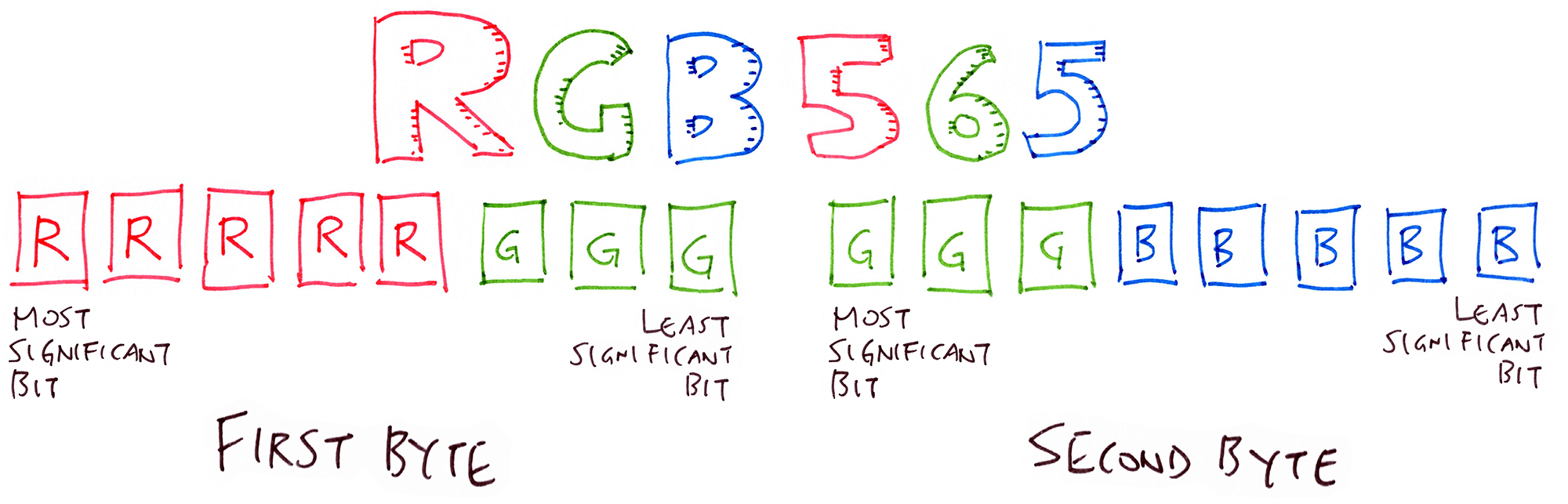
We call it RGB565 because it encodes 5 bits for Red, 6 bits for Green and 5 bits for Blue. Which adds up to 16 bits, or 2 bytes.
For more details on PineTime's ST7789 Display Controller, check out this article...
Optimising PineTime’s Display Driver with Rust and Mynewt
Now that we can draw a line, let's extend the code to render the entire Boot Graphic, line by line.
From display.c we have seen the fastest, simplest functions to draw coloured lines with PineTime's ST7789 Display Controller.
Now let's call these functions to render the Boot Graphic in display.c...
#define BATCH_SIZE  256  //  Max number of SPI data bytes to be transmitted

//  Screen Buffer Size: 240 * 240 * 2 / 1024 = 112.5 KB
#define ROW_COUNT 240
#define COL_COUNT 240
#define BYTES_PER_PIXEL 2

//  Flash Device for Image
#define FLASH_DEVICE 1  //  0 for Internal Flash ROM, 1 for External SPI Flash

/// Buffer for reading flash and writing to display
static uint8_t flash_buffer[BATCH_SIZE];

/// Display the image in SPI Flash to ST7789 display controller.
/// Derived from https://github.com/lupyuen/pinetime-rust-mynewt/blob/main/logs/spi-non-blocking.log
int pinetime_boot_display_image(void) {
    init_display();
    set_orientation(Landscape);

    //  Render each row of pixels.
    for (uint8_t row = 0; row < ROW_COUNT; row++) {
        uint8_t top = row;     //  Top row
        uint8_t bottom = row;  //  Bottom row (same as top)
        uint8_t left = 0;      //  Left column
        //  Render a batch of columns in that row.
        for (;;) {
            if (left >= COL_COUNT) { break; }

            //  How many columns we will render in a batch.
            uint16_t batch_columns = BATCH_SIZE / BYTES_PER_PIXEL;
            uint16_t right = left + batch_columns - 1;
            if (right >= COL_COUNT) { right = COL_COUNT - 1; }

            //  How many bytes we will transmit.
            uint16_t len = (right - left + 1) * BYTES_PER_PIXEL;

            //  Read the bytes from flash memory.
            uint32_t offset = ((top * COL_COUNT) + left) * BYTES_PER_PIXEL;
            hal_flash_read(FLASH_DEVICE, offset, flash_buffer, len);

            //  Set the display window.
            set_window(left, top, right, bottom);

            //  Write Pixels (RAMWR)
            write_command(RAMWR, NULL, 0);
            write_data(flash_buffer, len);

            //  Move to the next batch of columns.
            left = right + 1;
        }
    }
    return 0;
}
Note that we call hal_flash_read() like this to read len bytes starting at flash address offset from the SPI Flash into flash_buffer...
hal_flash_read(FLASH_DEVICE, offset, flash_buffer, len);
Thus the function pinetime_boot_display_image() above keeps reading from SPI Flash (starting at address 0) and blasts everything to the Display Controller, row by row, 256 data bytes at a time. It's blasting the entire Boot Graphic from SPI Flash to the Display Controller!
Here's the set_window() function in display.c that sets the display window coordinates...
/// Set the ST7789 display window to the coordinates (left, top), (right, bottom)
static int set_window(uint8_t left, uint8_t top, uint8_t right, uint8_t bottom) {
    //  Set Address Window Columns (CASET)
    write_command(CASET, NULL, 0);
    uint8_t col_para[4] = { 0x00, left, 0x00, right };
    write_data(col_para, 4);

    //  Set Address Window Rows (RASET)
    write_command(RASET, NULL, 0);
    uint8_t row_para[4] = { 0x00, top, 0x00, bottom };
    write_data(row_para, 4);
    return 0;
}
Remember that Enhanced MCUBoot needs to render the Boot Graphic the quickest and most reliable way possible?
We have accomplished that because...
The rendering code is highly predictable (or deterministic)
The code doesn't depend on the contents of SPI Flash... It blindly blasts the bitmap data from SPI Flash to the Display Controller. Even if the SPI Flash contains garbage! (Which displays garbage, of course).
Thus the rendering code will always terminate (without hanging). And it won't cause MCUBoot to crash or hang.
We don't compress the Boot Graphic. We don't use a Flash File System either.
Because compression or file system bugs (or badly-formatted data) may cause MCUBoot to crash or hang
There is no conversion or decompression of bitmap data
Hence it's very fast (Watch the video again)
We don't allow any background processing in MCUBoot
No multitasking, no Bluetooth Stack. Just single-threaded code for maximum predictability and reliability.
When adding functions to MCUBoot, we need to assume that multitasking (Task Scheduler) is disabled. Here's an example from display.c...
/// Sleep for the specified number of milliseconds
static void delay_ms(uint32_t ms) {
    #if MYNEWT_VAL(OS_SCHEDULING)  //  If Task Scheduler is enabled (i.e. not MCUBoot)...
        uint32_t delay_ticks = ms * OS_TICKS_PER_SEC / 1000;
        os_time_delay(delay_ticks);
    #else  //  If Task Scheduler is disabled (i.e. MCUBoot)...
        //  os_time_delay() doesn't work in MCUBoot because the Task Scheduler isn't started
        pinetime_boot_check_button();
    #endif  //  MYNEWT_VAL(OS_SCHEDULING)
}
Some system functions like os_time_delay() only work when the Task Scheduler is enabled. Since multitasking is disabled for MCUBoot, we'll have to use an alternative function like pinetime_boot_check_button().
We'll cover pinetime_boot_check_button() in a while.
How shall we load a PNG graphic file to PineTime's SPI Flash as the Boot Graphic? We'll find out next.
We have built a Rust desktop command-line tool that reads a PNG 24-bit RGB file (240 x 240 resolution), and converts it into ST7789's RGB565 format...
github.com/lupyuen/pinetime-graphic
To run the tool and convert a PNG file named pinetime-graphic.png...
# Assume Rust and cargo are already installed: https://rustup.rs
git clone https://github.com/lupyuen/pinetime-graphic
cd pinetime-graphic
cargo build
cargo run -v pinetime-graphic.png
The RGB565 values (115,200 bytes) will be dumped to the console like this...
0x00, 0x00, 0x00, 0x00, 0x00, 0x00, 0x00, 0x00, 0x00, 0x00, 0x00, 0x00, 0x00, 0x00, 0x00, 0x00,
0x00, 0x00, 0x00, 0x00, 0x00, 0x00, 0x00, 0x00, 0x00, 0x00, 0x00, 0x00, 0x00, 0x00, 0x00, 0x00,
...
0x05, 0xa3, 0x01, 0x20, 0x01, 0x20, 0x01, 0x20, 0x06, 0xe4, 0x07, 0xe5, 0x07, 0xe5, 0x07, 0xe5,
0x05, 0xe3, 0x02, 0xc1, 0x02, 0xa1, 0x03, 0x62, 0x07, 0xe5, 0x07, 0xe5, 0x07, 0xe5, 0x07, 0xc5,
...
Copy the converted RGB565 values and paste into libs/pinetime_boot/src/graphic.inc.
Then run this code on PineTime to load the converted RGB565 values into PineTime's SPI Flash: libs/pinetime_boot/src/write.c
#define BATCH_SIZE  4096  //  Max number of data bytes to be written in a batch
#define FLASH_DEVICE 1    //  Flash Device: 0 for Flash ROM, 1 for SPI Flash

//  Converted from PNG file by https://github.com/lupyuen/pinetime-graphic
static const uint8_t image_data[] = {  //  Should be 115,200 bytes
#include "graphic.inc"
};

/// Write a converted graphic file to SPI Flash
int pinetime_boot_write_image(void) {
    uint32_t offset = 0;
    for (;;) {
        if (offset >= sizeof(image_data)) { break; }
        //  How many bytes we will write.
        uint16_t len = BATCH_SIZE;
        if (offset + len >= sizeof(image_data)) {
            len = sizeof(image_data) - offset;
        }
        //  Erase the bytes.
        int rc = hal_flash_erase(FLASH_DEVICE, offset, len);
        assert(rc == 0);

        //  Write the bytes.
        rc = hal_flash_write(FLASH_DEVICE, offset, (void *) &image_data[offset], len);
        assert(rc == 0);
        offset += len;
    }
    return 0;
}
hal_flash_erase() and hal_flash_write() are defined as follows...
hal_flash_erase(id, offset, size)
Erase internal / external flash memory at the offset address, for size bytes. See hal_flash_erase
hal_flash_write(id, offset, buf, size)
Write internal / external flash memory from the buf buffer to the offset address, for size bytes. See hal_flash_write
Earlier we resolved never to modify MCUBoot code because the MCUBoot Bootloader is a Critical and Secure part of PineTime.
How shall we add new functions to MCUBoot, like rendering the Boot Graphic?
Fortunately MCUBoot provides two spots for us to hook on additional functions...
Start of MCUBoot: MCUBoot calls our custom function via sysinit()
End of MCUBoot: MCUBoot calls our custom function via boot_custom_start()
Here's how the hooks are implemented in the Mynewt version of MCUBoot: mcuboot/boot/mynewt/src/main.c
//  MCUBoot starts here.
int main(void) {

#if defined(MCUBOOT_HAVE_LOGGING)
    //  Initialise Mynewt drivers and libraries.
    sysinit();
#else
    //  By Default: Don't call sysinit() to initialise Mynewt drivers and libraries.
#endif

    //  MCUBoot does its work here. Swaps Active and Standby Firmware if necessary.
    boot_go(&rsp);
    flash_device_base(rsp.br_flash_dev_id, &flash_base);
    //  MCUBoot has completed its work.

#if MYNEWT_VAL(BOOT_CUSTOM_START)
    //  Call custom boot function to start the Application Firmware
    boot_custom_start(flash_base, &rsp);
#else
    //  By Default: Start the Application Firmware directly
    hal_system_start((void *)(flash_base + rsp.br_image_off + rsp.br_hdr->ih_hdr_size));
#endif

    return 0;
}
Let's enable both MCUBoot hooks in our Enhanced MCUBoot for PineTime: targets/nrf52_boot
sysinit() HookTo enable the sysinit() hook when MCUBoot starts, we define MCUBOOT_HAVE_LOGGING in targets/nrf52_boot/pkg.yml...
# Package Dependencies: MCUBoot is dependent on these drivers and libraries.
pkg.deps:
    - "libs/semihosting_console"  #  Semihosting Console
    - "libs/pinetime_boot"        #  Render boot graphic and check for rollback

#  C compiler flags
pkg.cflags:
    - -DMCUBOOT_HAVE_LOGGING=1  #  So that sysinit() will be run, needed for displaying boot graphic
We have added two libraries to MCUBoot...
semihosting_console Library: Display debugging messages from MCUBoot via the Arm Semihosting Console (in OpenOCD).
The debugging messages are automatically disabled if PineTime's SWD Port is not connected.
pinetime_boot Library: Implements the Enhanced MCUBoot functions (like rendering the Boot Graphic).
More about pinetime_boot in a while.
boot_custom_start() HookTo enable the boot_custom_start() hook when MCUBoot completes its processing, we set BOOT_CUSTOM_START to 1 in targets/nrf52_boot/syscfg.yml...
# MCUBoot Bootloader Settings
syscfg.vals:
    BOOT_CUSTOM_START:        1  # Use custom boot function boot_custom_start()
    OS_MAIN_STACK_SIZE:    1024  # Small stack size: 4 KB
    MSYS_1_BLOCK_COUNT:      64  # Allocate MSYS buffers for Semihosting Console

    # Hardware Settings
    SPIFLASH:                 1  # Enable SPI Flash
    SPI_0_MASTER:             1  # Enable SPI port 0 for ST7789 display and SPI Flash
We have enabled the SPI port (SPI_0_MASTER) as well as the SPI Flash driver (SPIFLASH).
MSYS_1_BLOCK_COUNT needs to be set so that debugging messages from MCUBoot will appear on the Arm Semihosting Console (in OpenOCD). The Semihosting Console Library uses MSYS buffers for buffering debugging messages in RAM.
Let's find out how the PineTime Boot Library pinetime_boot implements the MCUBoot custom hooks.
Previously we have enabled both hooks in PineTime's Enhanced MCUBoot...
sysinit(): Called by MCUBoot when it starts
boot_custom_start(): Called by MCUBoot when it has completed its work
Let's learn how both hooks are handled by the PineTime Boot Library: libs/pinetime_boot
sysinit() Hooksysinit() is a special function that's automatically generated when we build the Bootloader and Application Firmware in Mynewt.
Here's the auto-generated sysinit() function for our Enhanced MCUBoot Bootloader: bin/targets/nrf52_boot/generated/src/nrf52_boot-sysinit-app.c
void sysinit_app(void) {
    //  Stage 0.0: os_pkg_init (kernel/os)
    os_pkg_init();

    //  Stage 2.0: flash_map_init (sys/flash_map)
    flash_map_init();

    //  Stage 20.0: console_pkg_init (libs/semihosting_console)
    console_pkg_init();

    //  Stage 100.0: mfg_init (sys/mfg)
    mfg_init();
    //  Stage 100.1: modlog_init (sys/log/modlog)
    modlog_init();

    //  Stage 900.0: pinetime_boot_init (libs/pinetime_boot)
    pinetime_boot_init();
}
sysinit() is aliased to sysinit_app(). This function is called when our Bootloader starts. It initialises the Mynewt operating system, drivers and libraries.
Note that sysinit() calls our custom function pinetime_boot_init() when the Bootloader starts.
How did we add pinetime_boot_init() to sysinit()?
By configuring the PineTime Boot Library like this: libs/pinetime_boot/pkg.yml
pkg.init:
    # pinetime_boot should be initialised last, when SPI and Semihosting Console are up
    pinetime_boot_init: 900  # Call pinetime_boot_init() to initialise and render boot graphic
We configured pinetime_boot_init() to run at Stage 900, so that it will run after all drivers and libraries have been started (especially the SPI Flash Driver).
What's inside our pinetime_boot_init() function?
pinetime_boot_init() runs when MCUBoot starts. Here's what it does: libs/pinetime_boot/src/pinetime_boot.c
/// Init the display and render the boot graphic. Called by sysinit() during startup, defined in pkg.yml.
void pinetime_boot_init(void) {
    ...
    //  Display the Boot Graphic.
    pinetime_boot_display_image();
}
pinetime_boot_init() calls pinetime_boot_display_image() to display the Boot Graphic.
Earlier we have seen how pinetime_boot_display_image() blasts the Boot Graphic from SPI Flash to PineTime's Display Controller.
Thus our Boot Graphic is rendered when Enhanced MCUBoot starts!
boot_custom_start() Hookboot_custom_start() is called by MCUBoot when it has completed its work (like swapping the Active and Standby Firmware Images).
We define boot_custom_start() in our PineTime Boot Library like this: libs/pinetime_boot/src/pinetime_boot.c
/// Called by MCUBoot when it has completed its work.
void boot_custom_start(
    uintptr_t flash_base,
    struct boot_rsp *rsp
) {
    ...
    //  Start the Active Firmware Image. Copied from MCUBoot main().
    hal_system_start((void *)(
        flash_base +
        rsp->br_image_off +
        rsp->br_hdr->ih_hdr_size
    ));
}
boot_custom_start() calls hal_system_start() to jump to the Active Firmware Image, since our Enhanced MCUBoot Bootloader has completed its work.
In the next section we'll see that boot_custom_start() performs another function on PineTime: Rolling back the firmware when the watch button is pressed.
To prevent PineTime from getting bricked during firmware update, MCUBoot will automatically roll back the new firmware (Active Firmware) to the older firmware (Standby Firmware) if the new firmware fails to start properly (or fails to set the Firmware OK flag).
What if the PineTime Owner decides that the new firmware is not working properly, and wishes to roll back the firmware manually?
We shall check for Manual Firmware Rollback like this: If the Owner presses and holds the watch button for 5 seconds while the watch is booting up, the MCUBoot Bootloader shall roll back the firmware.
The manual rollback logic will be implemented in libs/pinetime_boot/src/pinetime_boot.c...
#define PUSH_BUTTON_IN  13  //  P0.13: PUSH BUTTON_IN
#define PUSH_BUTTON_OUT 15  //  P0.15/TRACEDATA2: PUSH BUTTON_OUT

/// Init the display and render the boot graphic. Called by sysinit() during startup, defined in pkg.yml.
void pinetime_boot_init(void) {
    //  Init the push button. The button on the side of the PineTime is disabled by default. To enable it, drive the button out pin (P0.15) high.
    //  While enabled, the button in pin (P0.13) will be high when the button is pressed, and low when it is not pressed.
    hal_gpio_init_in(PUSH_BUTTON_IN, HAL_GPIO_PULL_DOWN);  //  TODO: Doesn't seem to detect button press
    hal_gpio_init_out(PUSH_BUTTON_OUT, 1);
    hal_gpio_write(PUSH_BUTTON_OUT, 1);  //  Enable the button

    //  Display the image.
    pinetime_boot_display_image();
}

/// Called by MCUBoot when it has completed its work.
void boot_custom_start(
    uintptr_t flash_base,
    struct boot_rsp *rsp
) {
    //  Wait 5 seconds for button press.
    for (int i = 0; i < 15; i++) {
        pinetime_boot_check_button();
    }

    //  TODO: If button is pressed and held for 5 seconds, rollback the firmware.

    //  Start the Active Firmware Image. Copied from MCUBoot main().
    hal_system_start((void *)(
        flash_base +
        rsp->br_image_off +
        rsp->br_hdr->ih_hdr_size
    ));
}

/// Check whether the watch button is pressed
void pinetime_boot_check_button(void) {
    for (int i = 0; i < 1000000; i++) {
        //  TODO: Remember whether the button is pressed and held
        hal_gpio_read(PUSH_BUTTON_IN);  //  TODO: Doesn't seem to detect button press
    }
}
In pinetime_boot_init(), which is called when the MCUBoot Bootloader starts, we initialise the GPIO Pins for the watch button. Then we let MCUBoot do its work.
When MCUBoot has finished working, it calls boot_custom_start(). Here we wait 5 seconds and check whether the button has been pressed and held for 5 seconds.
If so, we roll back the firmware.
[ UPDATE: Check out the testing of Wireless Firmware Updates on PineTime ]
To test Enhanced MCUBoot Bootloader on PineTime, download the binaries here...
pinetime-rust-mynewt/releases/tag/v4.1.1
mynewt.*: Enhanced MCUBoot Bootloader (based on MCUBoot 1.5.0) that supports Boot Graphic and SPI Flash
my_sensor_app.*: Application Firmware (based on Mynewt+Rust) that supports firmware update over Bluetooth
boot-graphic.bin: Boot Graphic in RGB565 format (Hand-drawn PineTime Logo)
pinetime-rust-mynewt.7z: Mynewt Build Files generated on macOS
To install Enhanced MCUBoot Bootloader...
Flash the Enhanced MCUBoot Bootloader mynewt.bin to address 0x0 in Internal Flash ROM
Application Firmware Image (my_sensor_app.img, or your firmware image containing MCUBoot Image Header) should be flashed to address 0x8000 in Internal Flash ROM
During Firmware Update, the new firmware image (my_sensor_app.img, or your firmware image containing MCUBoot Image Header) should be flashed to address 0x40000 in External SPI Flash
Optional: Boot Graphic boot-graphic.bin should be flashed to address 0x0 in External SPI Flash.
Boot Graphic is in RGB565 format, 240 x 240 pixels, 2 bytes per pixel.
Use this tool to convert a 240 x 240 PNG file to RGB565: github.com/lupyuen/pinetime-graphic
We should see this on the PineTime screen...
When PineTime is powered on, we see white noise (snow) briefly as MCUBoot starts
MCUBoot renders the hand-drawn PineTime logo in under 1 second
MCUBoot waits 5 seconds for Manual Firmware Rollback (simulated for now)
MCUBoot starts the Application Firmware
Mynewt Application Firmware resets the Backlight and Display Controller, causing the screen to blank (needs to be fixed)
Mynewt Application Firmware switches on the Backlight. The hand-drawn PineTime logo previously rendered is now visible.
Mynewt Application Firmware erases the screen very slowly via the Rust driver for ST7789 Display Controller
Mynewt Application Firmware renders some shapes and the message "I AM PINETIME"
Here is the log that appears on Semihosting Console in OpenOCD...
Starting Bootloader...
Displaying image...
Image displayed
Button: 0
[INF] Primary image: magic=unset, swap_type=0x1, copy_done=0x3, image_ok=0x3
[INF] Scratch: magic=unset, swap_type=0x1, copy_done=0x3, image_ok=0x3
[INF] Boot source: primary slot
[INF] Swap type: none
Button: 0
Button: 0
Bootloader done
TMP create temp_stub_0
NET hwid 4a f8 cf 95 6a be c1 f6 89 ba 12 1a
NET standalone node
Testing flash...
Read Internal Flash ROM...
Read 0x0 + 20
  0x0000: 0x00 0x00 0x01 0x20 0xd9 0x00 0x00 0x00
  0x0008: 0x35 0x01 0x00 0x00 0x37 0x01 0x00 0x00
  0x0010: 0x00 0x00 0x00 0x00 0x00 0x00 0x00 0x00
  0x0018: 0x00 0x00 0x00 0x00 0x00 0x00 0x00 0x00
Read External SPI Flash...
Read 0x0 + 20
  0x0000: 0x00 0x00 0x00 0x00 0x00 0x00 0x00 0x00
  0x0008: 0x00 0x00 0x00 0x00 0x00 0x00 0x00 0x00
  0x0010: 0x00 0x00 0x00 0x00 0x00 0x00 0x00 0x00
  0x0018: 0x00 0x00 0x00 0x00 0x00 0x00 0x00 0x00
Flash OK
Rust test display
The Enhanced MCUBoot Bootloader for PineTime is now 22 KB in size. Here are the sizes of each MCUBoot component...
+ newt size -v nrf52_boot
Size of Application Image: app
Mem FLASH: 0x0-0x6000
Mem RAM: 0x20000000-0x20010000
  FLASH     RAM
     90     229 *fill*
   6863    5996 boot_bootutil.a
    124       0 boot_mynewt.a
     18       0 boot_mynewt_flash_map_backend.a
   1180       0 crypto_mbedtls.a
    392     444 hw_bsp_nrf52.a
     52       0 hw_cmsis-core.a
   1302      80 hw_drivers_flash_spiflash.a
    662       1 hw_hal.a
   4190      72 hw_mcu_nordic_nrf52xxx.a
   2022   18776 kernel_os.a
   1784      12 libc_baselibc.a
   1312     256 libs_pinetime_boot.a
    539      40 libs_semihosting_console.a
    548     128 sys_flash_map.a
      2       0 sys_log_modlog.a
    666      29 sys_mfg.a
     30       5 sys_sysinit.a
     48       0 util_mem.a
    100       0 nrf52_boot-sysinit-app.a
    768       0 libgcc.a
Loading compiler /Users/Luppy/PineTime/pinetime-rust-mynewt/repos/apache-mynewt-core/compiler/arm-none-eabi-m4, buildProfile debug

objsize
   text    data     bss     dec     hex filename
  22620     132   25504   48256    bc80 /Users/Luppy/PineTime/pinetime-rust-mynewt/bin/targets/nrf52_boot/app/boot/mynewt/mynewt.elf
[ UPDATE: Check out the testing of Wireless Firmware Updates on PineTime ]
While writing this article, PineTime Firmware Developers have provided plenty of valuable feedback. Here are the proposed enhancements based on their feedback...
Boot Graphic Compression: Reserving 112 KB of SPI Flash Memory for the Boot Graphic seems rather excessive. Surely we can compress the RGB555 bitmap and save space?
Yes! We shall be compressing the Boot Graphic as an enhancement.
The current version of Enhanced MCUBoot is focused on stability for easier testing, so no compression was used.
Meanwhile we'll look for a suitable bitmap compression module that performs efficiently on PineTime and doesn't crash when working on corrupted data.
Space for Bootloader Assets: 256 KB of SPI Flash Memory (4 MB) is reserved for Bootloader Assets (which includes the Boot Graphics)... Too much maybe?
Half of the space is now used by the uncompressed Boot Graphic. When we implement Boot Graphic Compression, we shall shrink the Bootloader Assets space.
What about the other half of the Bootloader Assets space?
The space may be used for storing graphical assets like icons, fonts, and animations. How we'll actually use the space will depend on this exciting new open source collaboration...
Collaboration with minodesign: With PineTime we start with a blank slate for creating a FOSSy Smart Watch. Since PineTime Owners will have full freedom to tweak their watches, we'll encounter interesting ownership questions like...
When you're a PineTime Owner, how would you show others that this watch is really yours?
Do we show your handwriting when PineTime starts up? Or a photo?
(It's a shame that all iPhones and Apple Watches look the same!)
We're happy to collaborate with minodesign to tackle these difficult questions.
We'll start by creating a Bootloader User Experience that showcases the Free and Open Source nature of PineTime. Stay tuned!
Onboarding of PineTime Firmware: Now that we have a stable Bootloader for PineTime that supports Wireless Firmware Updates... Let's bring onboard all PineTime Firmware Developers!
We are now testing various PineTime operating systems for Wireless Firmware Updates: FreeRTOS, Mynewt + Rust, possibly others.
PineTime will be the very first gadget that lets you switch to a different operating system wirelessly... And switch back!
Some PineTime operating systems require more integration coding than others. I'll be helping to integrate wasp-os (MicroPython) with the NimBLE Bluetooth Stack.
If you're keen to solve these challenges the open source way, come join us!
Chat with us on Matrix / Discord / Telegram / IRC: PineTime Community
PineTime MCUBoot Bootloader v5.0.4 (17 Sep 2020) and later releases will activate the nRF52 Watchdog. The Watchdog needs to be tickled every 7 seconds or PineTime will forcibly reboot.
This is needed in case the firmware is stuck in a loop or having peripheral issues (like SPI Bus Corruption).
The Watchdog is activated in libs/pinetime_boot/src/pinetime_boot.c...
void setup_watchdog() {
  NRF_WDT->CONFIG &= ~(WDT_CONFIG_SLEEP_Msk << WDT_CONFIG_SLEEP_Pos);
  NRF_WDT->CONFIG |= (WDT_CONFIG_HALT_Run << WDT_CONFIG_SLEEP_Pos);

  NRF_WDT->CONFIG &= ~(WDT_CONFIG_HALT_Msk << WDT_CONFIG_HALT_Pos);
  NRF_WDT->CONFIG |= (WDT_CONFIG_HALT_Pause << WDT_CONFIG_HALT_Pos);

  /* timeout (s) = (CRV + 1) / 32768 */
  const int timeoutSeconds = 7; // 7 seconds
  uint32_t crv = (((timeoutSeconds*1000u) << 15u) / 1000) - 1;
  NRF_WDT->CRV = crv;

  /* Enable reload requests */
  NRF_WDT->RREN = (WDT_RREN_RR0_Enabled << WDT_RREN_RR0_Pos);

  /* Start */
  NRF_WDT->TASKS_START = 1;
}
For Application Firmware created with Mynewt, we may set SANITY_INTERVAL to 5000 to tickle the Watchdog automatically every 5 seconds: apps/my_sensor_app/syscfg.yml
syscfg.vals:
    # The default PineTime bootloader will setup a 7 second watchdog
    SANITY_INTERVAL: 5000  #  Tickle the watchdog every 5 seconds, that the watchdog won't trigger a reboot
To simulate the Watchdog with Mynewt Application Firmware, set WATCHDOG_INTERVAL to 7000: apps/my_sensor_app/syscfg.yml
syscfg.vals:
    WATCHDOG_INTERVAL: 7000  #  If watchdog is not set, set it to 7 seconds
Note that once the Watchdog is activated (by the Bootloader or Application Firmware), the Watchdog may not be disabled or changed to a different timeout value.
In the PineTime MCUBoot Bootloader we also override the default Mynewt Non-Maskable Interrupt Handler, which is triggered by an Assertion Failure (e.g. due to SPI Bus Corruption).
In our custom Non-Maskable Interrupt Handler (and Hard Fault Handler), the Bootloader blinks 4 times quickly and reboots: libs/pinetime_boot/src/pinetime_boot.c
/// Blink 4 times and reboot
static void blink_and_restart() {
    //  Blink the screen quickly 4 times
    blink_backlight(4, 4);
    //  Then reboot, which fixes the SPI Bus
    NVIC_SystemReset();
}

/// In case of Non-Maskable Interrupt (e.g. assertion failure), blink 4 times and reboot.
/// Assertion failure may be due to SPI Bus corruption, which causes SPI Flash access to fail in spiflash_identify() in repos/apache-mynewt-core/hw/drivers/flash/spiflash/src/spiflash.c
void NMI_Handler() {
    //  Blink and restart
    blink_and_restart();
}

/// In case of Hard Fault, blink 4 times and reboot
void HardFault_Handler() {
    //  Blink and restart
    blink_and_restart();
}
The default Mynewt Non-Maskable Interrupt Handler and Hard Fault Handler will loop infinitely, and would have hung our Bootloader.
Follow these steps to build the MCUBoot Bootloader on Linux (including Raspberry Pi) and macOS...
For macOS: Install OpenOCD from The xPack OpenOCD. Older versions of OpenOCD are known to have problems flashing with ST-Link.
Download and unzip OpenOCD for macOS: gnu-mcu-eclipse-openocd-0.10.0-11-20190118-1134-macos.tgz
Install GCC and Python build tools for Linux (or the macOS equivalent)...
sudo apt install gcc gcc-arm-none-eabi python3 make
For Majaro and Arch Linux...
sudo pacman -S arm-none-eabi-gcc
Install rustup with support for nightly target thumbv7em-none-eabihf.
Follow the instructions at https://rustup.rs/
Press Enter to select 1) Proceed with installation (default)
Then execute...
# Latest nightly-2020-04-20 fails with asm error, so we use nightly-2020-02-16
source $HOME/.cargo/env
rustup default nightly-2020-02-16
rustup update
rustup target add thumbv7em-none-eabihf
Install the newt build tool for Mynewt. Refer to these scripts...
scripts/install-version.sh: To set the version numbers
scripts/install-pi.sh: To build and install newt, look under the section "Build newt"
Download the source files to ~/pinetime...
mkdir ~/pinetime
cd ~/pinetime
git clone --recursive --branch master https://github.com/lupyuen/pinetime-rust-mynewt
Update the MCUBoot version number to 1.3.1. Edit ~/pinetime/pinetime-rust-mynewt/project.yml
Change...
repository.mcuboot:
    type: github
    vers: 1.5.0
to...
repository.mcuboot:
    type: github
    vers: 1.3.1
Download the source code for Mynewt, NimBLE and MCUBoot...
cd ~/pinetime/pinetime-rust-mynewt
newt install
We should see...
Downloading repository mynewt-core (commit: master) from https://github.com/apache/mynewt-core.git
Downloading repository mynewt-mcumgr (commit: master) from https://github.com/apache/mynewt-mcumgr.git
Downloading repository mynewt-nimble (commit: master) from https://github.com/apache/mynewt-nimble.git
Downloading repository mcuboot (commit: master) from https://github.com/JuulLabs-OSS/mcuboot.git
Making the following changes to the project:
    install apache-mynewt-core (1.7.0)
    install apache-mynewt-nimble (1.2.0)
    install mcuboot (1.3.1)
apache-mynewt-core successfully installed version 1.7.0
apache-mynewt-nimble successfully installed version 1.2.0
Error: Error updating "mcuboot": error: The following untracked working tree files would be overwritten by checkout:
        ext/mbedtls/include/mbedtls/check_config.h
        ext/mbedtls/include/mbedtls/config.h
Please move or remove them before you switch branches.
Aborting
Ignore the mcuboot error above and proceed to the next step.
Restore the MCUBoot version number to 1.5.0. Edit ~/pinetime/pinetime-rust-mynewt/project.yml
Change...
repository.mcuboot:
    type: github
    vers: 1.3.1
to...
repository.mcuboot:
    type: github
    vers: 1.5.0
Download version 1.5.0 of MCUBoot to repos/mcuboot
cd ~/pinetime/pinetime-rust-mynewt/repos
rm -rf mcuboot
git clone --recursive --branch v1.5.0 https://github.com/JuulLabs-OSS/mcuboot
Why are we doing this? Because we are using a more recent version of MCUBoot (1.5.0), but that's not in sync with the older Mynewt version (1.7.0). This will cause newt install to fail. Hence we do this workaround to force Mynewt to build with the newer MCUBoot.
Build the MCUBoot Bootloader...
cd ~/pinetime/pinetime-rust-mynewt
scripts/nrf52/build-boot.sh
We should see...
Linking pinetime/pinetime-rust-mynewt/bin/targets/nrf52_boot/app/boot/mynewt/mynewt.elf
Target successfully built: targets/nrf52_boot
+ newt size -v nrf52_boot
Size of Application Image: app
Mem FLASH: 0x0-0x6000
Mem RAM: 0x20000000-0x20010000
  FLASH     RAM
     90     229 *fill*
   6823    5996 boot_bootutil.a
    124       0 boot_mynewt.a
     18       0 boot_mynewt_flash_map_backend.a
   1182       0 crypto_mbedtls.a
    392     444 hw_bsp_nrf52.a
     52       0 hw_cmsis-core.a
   1280      80 hw_drivers_flash_spiflash.a
    654       1 hw_hal.a
   4192      72 hw_mcu_nordic_nrf52xxx.a
   2006   18776 kernel_os.a
   1930      12 libc_baselibc.a
   1478     256 libs_pinetime_boot.a
    529      40 libs_semihosting_console.a
    544     128 sys_flash_map.a
      2       0 sys_log_modlog.a
    632      29 sys_mfg.a
     30       5 sys_sysinit.a
     48       0 util_mem.a
    100       0 nrf52_boot-sysinit-app.a
    756       0 libgcc.a
Loading compiler pinetime/pinetime-rust-mynewt/repos/apache-mynewt-core/compiler/arm-none-eabi-m4, buildProfile debug

objsize
   text    data     bss     dec     hex filename
  22792     132   25504   48428    bd2c pinetime/pinetime-rust-mynewt/bin/targets/nrf52_boot/app/boot/mynewt/mynewt.elf
Edit ~/pinetime/pinetime-rust-mynewt/scripts/config.sh
If we're using ST-Link v2 for flashing PineTime, set swd_device as follows...
#  Select ST-Link v2 as SWD Programmer
swd_device=scripts/nrf52/swd-stlink.ocd
If we're using Raspberry Pi SPI for flashing PineTime, set swd_device as follows...
#  Select Raspberry Pi as SWD Programmer
swd_device=scripts/nrf52-pi/swd-pi.ocd
Edit ~/pinetime/pinetime-rust-mynewt/scripts/nrf52/flash-boot.sh
Change openocd/bin/openocd to the path of our installed openocd (for ST-Link) or openocd-spi (for Raspberry Pi)...
#  Flash the device
openocd/bin/openocd \
    -f $swd_device \
    -f scripts/nrf52/flash-boot.ocd
Edit ~/pinetime/pinetime-rust-mynewt/scripts/nrf52/flash-boot.ocd
The path of the built firmware file is defined in ~/pinetime/pinetime-rust-mynewt/scripts/nrf52/flash-boot.ocd. We shouldn't need to change this.
# For MCUBoot (debugging not supported):
program bin/targets/nrf52_boot/app/boot/mynewt/mynewt.elf.bin verify 0x00000000
Flash the bootloader...
scripts/nrf52/flash-boot.sh
We should see...
> Executing task in folder pinetime-rust-mynewt: bash -c -l ' scripts/nrf52/flash-boot.sh && echo ✅ ◾ ️Done! ' <

+ source scripts/config.sh
++ swd_device=scripts/nrf52/swd-stlink.ocd
+ openocd/bin/openocd -f scripts/nrf52/swd-stlink.ocd -f scripts/nrf52/flash-boot.ocd
GNU MCU Eclipse 64-bit Open On-Chip Debugger 0.10.0+dev-00462-gdd1d90111 (2019-01-15-13:49)
Licensed under GNU GPL v2
For bug reports, read
        http://openocd.org/doc/doxygen/bugs.html
debug_level: 0
adapter speed: 1000 kHz
force hard breakpoints
Stopping...
target halted due to breakpoint, current mode: Thread
xPSR: 0x21000000 pc: 0x000023a4 msp: 0x2000ff9c

Flashing Bootloader...
target halted due to debug-request, current mode: Thread
xPSR: 0x01000000 pc: 0x000000d8 msp: 0x20010000
Enabled ARM Semihosting to show debug output
semihosting is enabled
** Programming Started **
auto erase enabled
target halted due to breakpoint, current mode: Thread
xPSR: 0x61000000 pc: 0x2000001e msp: 0x20010000, semihosting
wrote 24576 bytes from file bin/targets/nrf52_boot/app/boot/mynewt/mynewt.elf.bin in 0.729124s (32.916 KiB/s)
** Programming Finished **
** Verify Started **
target halted due to breakpoint, current mode: Thread
xPSR: 0x61000000 pc: 0x2000002e msp: 0x20010000, semihosting
verified 22876 bytes in 0.114145s (195.715 KiB/s)
** Verified OK **

Restarting...
target halted due to debug-request, current mode: Thread
xPSR: 0x01000000 pc: 0x000000d8 msp: 0x20010000, semihosting

**** Done!
For ST-Link, check that the Adapter Speed is set to 1000 kHz. OpenOCD won't work at higher speeds.
adapter speed: 1000 kHz
If the flashing fails, check whether any openocd processes are running in the background, and kill them.
Alternatively, use PineTime Updater to flash the bootloader...
Select Downloaded File
Select the file bin/targets/nrf52_boot/app/boot/mynewt/mynewt.elf.bin
Enter address 0x0
Download one of the following Application Firmware Images...
Mynewt: my_sensor_app.img
FreeRTOS: jf.bin
For other versions of the Application Firmware Image, see this article
Edit ~/pinetime/pinetime-rust-mynewt/scripts/nrf52/flash-app.sh
Change openocd/bin/openocd to the path of our installed openocd (for ST-Link) or openocd-spi (for Raspberry Pi)...
#  Flash the device
openocd/bin/openocd \
    -f $swd_device \
    -f scripts/nrf52/flash-app.ocd
Edit ~/pinetime/pinetime-rust-mynewt/scripts/nrf52/flash-app.ocd
Change bin/targets/nrf52_my_sensor/app/apps/my_sensor_app/my_sensor_app.img to the path of the downloaded Application Firmware Image File...
program bin/targets/nrf52_my_sensor/app/apps/my_sensor_app/my_sensor_app.img verify 0x00008000
Flash the application...
scripts/nrf52/flash-app.sh
We should see...
> Executing task in folder pinetime-rust-mynewt: bash -c -l ' scripts/nrf52/flash-app.sh && echo ✅ ◾ ️Done! ' <

+ source scripts/config.sh
++ swd_device=scripts/nrf52/swd-stlink.ocd
+ openocd/bin/openocd -f scripts/nrf52/swd-stlink.ocd -f scripts/nrf52/flash-app.ocd
GNU MCU Eclipse 64-bit Open On-Chip Debugger 0.10.0+dev-00462-gdd1d90111 (2019-01-15-13:49)
Licensed under GNU GPL v2
For bug reports, read
        http://openocd.org/doc/doxygen/bugs.html
debug_level: 0
adapter speed: 1000 kHz
force hard breakpoints
Stopping...
target halted due to debug-request, current mode: Thread
xPSR: 0x61000000 pc: 0x000001ca msp: 0x2000ffd8

Flashing Application...
target halted due to debug-request, current mode: Thread
xPSR: 0x01000000 pc: 0x000000d8 msp: 0x20010000
Enabled ARM Semihosting to show debug output
semihosting is enabled
** Programming Started **
auto erase enabled
target halted due to breakpoint, current mode: Thread
xPSR: 0x61000000 pc: 0x2000001e msp: 0x20010000, semihosting
wrote 143360 bytes from file bin/targets/nrf52_my_sensor/app/apps/my_sensor_app/my_sensor_app.img in 3.606276s (38.821 KiB/s)
** Programming Finished **
** Verify Started **
target halted due to breakpoint, current mode: Thread
xPSR: 0x61000000 pc: 0x2000002e msp: 0x20010000, semihosting
verified 139268 bytes in 0.363909s (373.731 KiB/s)
** Verified OK **
For ST-Link, check that the Adapter Speed is set to 1000 kHz. OpenOCD won't work at higher speeds.
adapter speed: 1000 kHz
If the flashing fails, check whether any openocd processes are running in the background, and kill them.
PineTime reboots (with the reset init OpenOCD Command)...
Restarting...
target halted due to debug-request, current mode: Thread
xPSR: 0x01000000 pc: 0x000000d8 msp: 0x20010000, semihosting
Enabled ARM Semihosting to show debug output
semihosting is enabled
PineTime starts MCUBoot Bootloader...
**** Done! Press Ctrl-C to exit...
Starting Bootloader...
Displaying image...
Image displayed
Check button: 0
[INF] Primary image: magic=good, swap_type=0x4, copy_done=0x1, image_ok=0x1
[INF] Scratch: magic=bad, swap_type=0x1, copy_done=0x2, image_ok=0x2
[INF] Boot source: none
[INF] Swap type: none
Waiting 5 seconds for button...
Waited for button: 0
Bootloader done
Finally PineTime starts the Application Firmware...
TMP create temp_stub_0
NET hwid 4a f8 cf 95 6a be c1 f6 89 ba 12 1a
NET standalone node
Firmware tests internal and external flash memory...
Testing flash...
Read Internal Flash ROM...
Read 0x0 + 20
0x0000: 0x00 0x00 0x01 0x20 0xd9 0x00 0x00 0x00
0x0008: 0x35 0x01 0x00 0x00 0x37 0x01 0x00 0x00
0x0010: 0x00 0x00 0x00 0x00 0x00 0x00 0x00 0x00
0x0018: 0x00 0x00 0x00 0x00 0x00 0x00 0x00 0x00
Read External SPI Flash...
Read 0x0 + 20
0x0000: 0x01 0x00 0x00 0x00 0xf0 0x0f 0xff 0xf7
0x0008: 0x6c 0x69 0x74 0x74 0x6c 0x65 0x66 0x73
0x0010: 0x2f 0xe0 0x00 0x10 0x00 0x00 0x02 0x00
0x0018: 0x00 0x02 0x00 0x00 0x00 0x20 0x00 0x00
Flash OK
When we connect with newtmgr, the Bluetooth LE events are shown...
Starting BLE...
BLE started
Rust test display 1.0.0
Rust touch sensor
connection established; status=0 handle=1 our_ota_addr_type=1 our_ota_addr= our_id_addr_type=1 our_id_addr= peer_ota_addr_type=0 peer_ota_addr= peer_id_addr_type=0 peer_id_addr= conn_itvl=6 conn_latency=0 supervision_timeout=72 encrypted=0 authenticated=0 bonded=0

mtu update event; conn_handle=1 cid=4 mtu=256
subscribe event; conn_handle=1 attr_handle=30 reason=1 prevn=0 curn=1 previ=0 curi=0
subscribe event; conn_handle=1 attr_handle=30 reason=2 prevn=1 curn=0 previ=0 curi=0
disconnect; reason=531 handle=1 our_ota_addr_type=1 our_ota_addr= our_id_addr_type=1 our_id_addr= peer_ota_addr_type=0 peer_ota_addr= peer_id_addr_type=0 peer_id_addr= conn_itvl=6 conn_latency=0 supervision_timeout=72 encrypted=0 authenticated=0 bonded=0
Alternatively, use PineTime Updater to flash the Application Firmware...
Select Downloaded File
Enter the path of the downloaded Application Firmware Image File
Enter address 0x8000
[ UPDATE: Check out the testing of Wireless Firmware Updates on PineTime ]
Got a question, comment or suggestion? Create an Issue or submit a Pull Request here...