Testing the Rust and Mynewt OS driver for the Touch Controller on PineTime Smart Watch by Pine64
Building a Rust Driver for PineTime’s Touch Controller
UPDATE: This code in this article has been archived in the pre-lvgl branch of pinetime-rust-mynewt. The pinetime-rust-mynewt firmware has been revamped to support Rust Watch Faces on LVGL. Check out the updates
Pretend you’re my IoT student. I give you a PineTime Smart Watch and challenge you to “Make it work… Especially the touch screen!” The Touch Screen appears to be lacking some documentation. What would you do?
PineTime Touch Screen = Touch Panel + Display Panel
We carefully pry open the PineTime Smart Watch with tweezers (or forceps) and examine the Touch Screen. It looks like a single chunk of plastic… But it’s actually two delicate pieces fused together: Touch Panel and Display Panel…
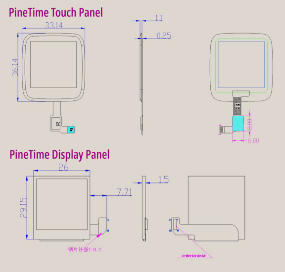
PineTime Touch Panel and Display Panel. From http://files.pine64.org/doc/datasheet/pinetime/PineTime%20LCD%20Panel.jpg and http://files.pine64.org/doc/datasheet/pinetime/PineTime%20Touch%20Panel.jpg
The Touch Panel and Display Panel are connected to the I2C and SPI connectors on the PineTime board…
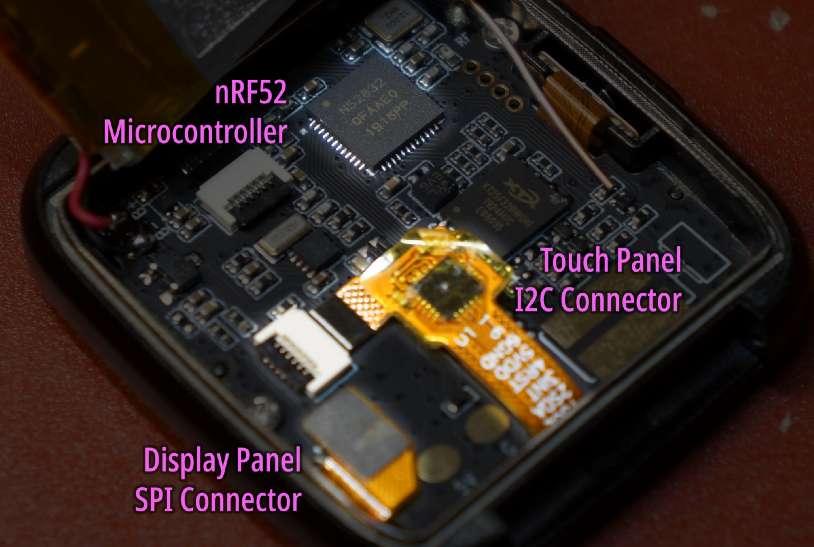
Connectors for ST7789 Display Controller and Hynitron CST816S Capacitive Touch Controller
Last week we have programmed the ST7789 Display Controller (via SPI) to render colour text and graphics on the Display Panel. This week we’ll look at the Hynitron CST816S Capacitive Touch Controller for PineTime’s Touch Panel…
Probing PineTime’s I2C Bus for Touch Controller
The PineTime Touch Controller is connected to the nRF52 Microcontroller via an I2C Bus. That stands for Inter-Integrated Circuit and is pronounced “I-squared-C”. (I used to call it “I-two-C” until my IoT students corrected me)
News Flash! I2C works more like a Light Rail transit line than a Bus. It runs on two rails (wires), shuttles tiny packets of passengers (data) between a Main Station (Master Microcontroller) and Sub Stations (Slave Devices)…
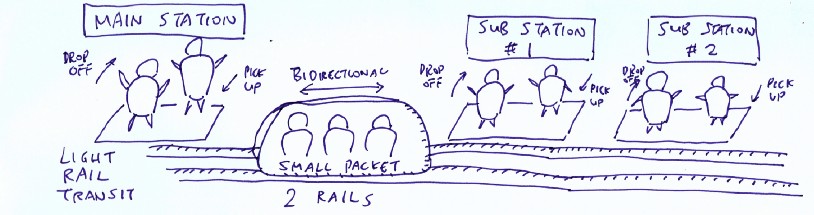
Light Rail Transit Line
In Light Rail, the train is sent from the Main Station to each Sub Station to drop off passengers. And we expect the train to pick up passengers from each Sub Station. A Sub Station with drop-offs but no pick-ups will be so spooky… like a Ghost Station!

I2C (Inter-Integrated Circuit) Bus on PineTime
Thankfully there are no Ghost Stations in I2C… When the Microcontroller sends a packet to a Slave Device at a particular address, the Slave Device must respond with another packet. This called I2C Probing and the Rust code on PineTime looks like this…
Probing the I2C Bus on PineTime to discover I2C devices. From https://github.com/lupyuen/stm32bluepill-mynewt-sensor/blob/pinetime/rust/app/src/touch_sensor.rs
There are only 128 possible I2C Addresses (0 to 127) so it’s feasible to identify all I2C Slave Devices by probing each address. (Here’s a list of I2C Addresses for popular devices)
Running the above code on
PineTime we find two devices on our I2C Bus, at I2C Addresses 0x18 and 0x44. That’s the Accelerometer and Heart Rate
Sensor. (I verified against the
docs)
But where’s the Touch Controller? Do Ghost Stations really exist on I2C?
PineTime Touch Controller responds to Special Events
Back to our Light Rail analogy… Suppose we have a Sub Station that serves an Amusement Park. The Sub Station operates on special occasions like weekends and holidays. Most of the time it would appear as a Ghost Station… Coming to life only on special occasions!
What is this “Special Event" that brings our Touch Controller to life?
Maybe it’s low on power? This power problem happens often with wireless gadgets like NB-IoT. We connect the 5 Volt power from the ST-Link USB dongle and… Nothing changes! (Though the PineTime Battery gets properly charged now… Nice!)
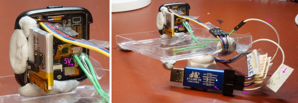
Connecting the 5V Charging Pad on PineTime to the 5V Pin of ST-Link with a folded loop of Single Core Wire (22 AWG)
(Don’t forget the “Only One Power Source” OOPS Rule… Our computer’s USB port supplies both 3.3 Volt and 5 Volt power sources… Never use two different power sources… OOPS!)
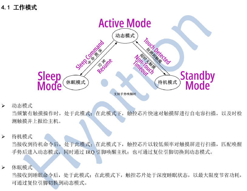
Touch Controller State Transition Diagram from http://files.pine64.org/doc/datasheet/pinetime/CST816S%E6%95%B0%E6%8D%AE%E6%89%8B%E5%86%8CV1.1.pdf. English Translation: https://wiki.pine64.org/images/5/51/CST816S%E6%95%B0%E6%8D%AE%E6%89%8B%E5%86%8CV1.1.en.pdf
We stare hard at this State Transition Diagram from the Touch Controller doc. (The English Translation looked alien so we’re using the original Chinese version with my translation) What is it trying to tell us?
It says that the Touch Controller can be woken from the Standby Mode… By Touch!
We tap the screen… Sure enough our Ghost Station comes to life! Our Touch Controller needs a little tap (the “Special Event”) to wake it up and respond to I2C packets. Mystery solved!
With screen tapping and I2C
probing, we finally locate PineTime’s Touch Controller… At I2C Address
0x15
I2C Streaming with PineTime Touch Controller
To discover which parts of the screen are touched (up to 10 points), we need to read 63 bytes from the PineTime Touch Controller… That’s 63 consecutive I2C Registers, 1 byte per register!
There’s an efficient way to read 63 consecutive I2C Registers from the PineTime Touch Controller. Some people call it Bulk Reading but let’s call it I2C Streaming.
Ever used a Rubber Hose to siphon petrol / gasoline / fish tank water? We suck a bit of air out of the Rubber Hose, maybe we’ll taste a bit of the petrol / gasoline / fish tank water (whoa that’s nasty), and the liquid comes streaming out. (Yes you can remove the hose from your mouth now!)
The liquid keeps streaming until
you stop it. I2C Streaming works just like that… We instruct the Touch Controller (via its I2C Address
0x15) to send us the value of I2C Register #0. The Touch Controller will stream a list of consecutive I2C
Register values (Register #0, #1, #2, …) Until we receive 63
values and we tell the Touch Controller “Stop!!!”
I2C Streaming runs in five steps like this…
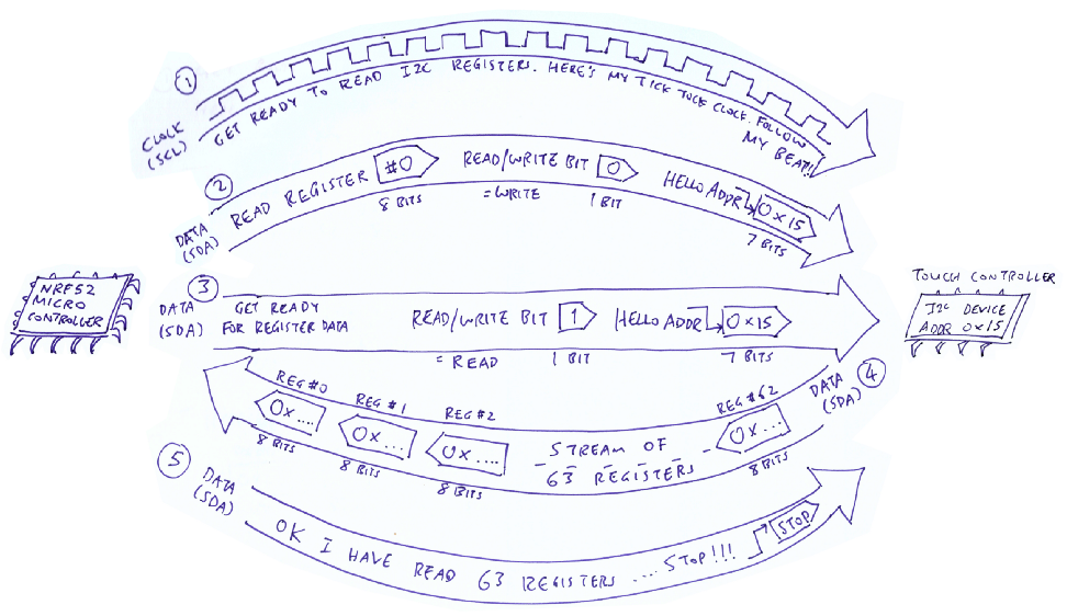
Steps to stream I2C Registers #0 to #62 from the I2C Touch Controller at I2C Address 0x15
Steps 1
through 5 are explained in the Rust code below that reads a range of I2C Registers
(Registers #0 to #62,
total 63 Registers) from the Touch Controller (at I2C Address 0x15)
Rust code to read a range of I2C Registers from an I2C Device on PineTime. The steps in the comments refer to the steps in the diagram above. From https://github.com/lupyuen/stm32bluepill-mynewt-sensor/blob/pinetime/rust/app/src/touch_sensor.rs
Yep the code looks alarming with
the unsafe blocks (because we are calling C APIs from Rust).
Eventually we should implement the I2C Interface for Rust Embedded HAL… And the unsafe blocks will be gone forever.
Convert PineTime Touch Data
The PineTime Touch Controller generates 63 bytes of raw touch data on every touch. (According to the reference code here) When converted, these 63 bytes produce 10 points of touch information. Each point of touch information contains…
1️⃣ X
(Horizontal) and Y (Vertical) Coordinates of the touched point. (0, 0) represents top left, (239, 239) represents bottom right.
2️⃣ Action: Whether the point was just touched, just untouched or kept in contact
3️⃣ Finger: A number that identifies the finger that touched the point
4️⃣ Pressure: How hard the point was touched
5️⃣ Area: Size of the touched area
63 bytes of raw touch data converted to 10 points of touch information. This is the Rust representation of the 10 touch points. From https://github.com/lupyuen/stm32bluepill-mynewt-sensor/blob/pinetime/rust/app/src/touch_sensor.rs
That’s a lot of information for each point touched… Why do we need so much information? Why the finger-pointing?
Think of the classic 2010 iPad game Fruit Ninja… The game tracks the swiping motion of each finger to figure out which fruits (and bombs) you’re slashing. So the tracking of each finger is important for swiping-based apps. (Like Tinder)
The Touch Controller doesn’t really know whether you touched the screen with your left forefinger or your right thumb (or your nose)… It just assigns a number to the finger (or appendage) that’s swiping the screen. The Touch Action (touched / untouched / in contact) is necessary to determine whether this is the start, middle or end of a swipe.
Based on the reference code, we derived the following Rust function for reading and converting the 63 bytes of raw touch data into touch points. Note that only the first 5 touch points out of 10 are converted. (Probably because it’s not meaningful to track 10 fingers on a tiny watch screen)
Rust code to convert raw touch data to touch point information. From https://github.com/lupyuen/stm32bluepill-mynewt-sensor/blob/pinetime/rust/app/src/touch_sensor.rs
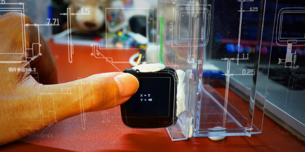
Display PineTime Touch Data
Now that we have the converted
touch data, let’s display the data on the screen to verify that we have converted the data correctly.
Here’s the Rust code that takes coordinates (X, Y) and displays
them as X = …, Y = … on the PineTime screen…
Rust code to display the touched coordinates on the screen. From https://github.com/lupyuen/stm32bluepill-mynewt-sensor/blob/pinetime/rust/app/src/display.rs
Notice that we passed a special
arrayvec::ArrayString
type to the write!() macro for storing the formatted text.
That’s because the write!() macro normally accepts a String type for storing formatted text… But String relies on Dynamic Heap Memory which we don’t support in our
Rust Application.
Why no Heap in our application? For Embedded Applications it’s a good practice to budget our memory requirements in advance and allocate our variables statically. Yes that means we have to do more planning while designing our programs… But we prevent problems like running out of heap memory (and heap fragmentation).
In the above code we have
budgeted 20 bytes in our fixed-size arrayvec::ArrayString buffer
for storing each formatted text string.
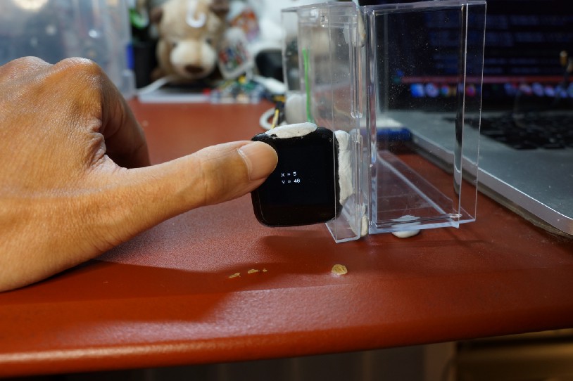
Displaying touched coordinates on PineTime screen
Mr Diego Barrios Romero has an excellent suggestion for handling Rust strings without heaps…
For the strings you can also use the
Stringtype from theheaplesscrate like thislet mut buffer:
heapless::String< heapless::consts::U64 >
= heapless::String::new();
Transform PineTime Touch Interrupt to Mynewt Event Callback
We have our PineTime Touch Controller all figured out… Reading the I2C Registers, converting the touch data and displaying the touch data. But something important is still missing…
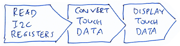
Reading, converting and displaying touch data
Remember the Ghost Station? We can’t read the I2C Registers on the Touch Controller unless the screen has been tapped… So how will we know when to read the registers?
Need to handle the Touch Interrupt and get an Event Callback first
Fortunately the Touch Controller generates a Touch Interrupt every time the screen is tapped. So let’s hook on to the Touch Interrupt and do the touch processing there!
Assigning an Interrupt Handler for Touch Interrupt. From https://github.com/lupyuen/stm32bluepill-mynewt-sensor/blob/pinetime/rust/app/src/touch_sensor.rs
The Touch Interrupt is raised via
a normal GPIO Pin (P0.28). In the Rust code above, we ask Mynewt
OS to watch out for the Touch Interrupt on the GPIO Pin, and call touch_interrupt_handler() when the GPIO Pin switches from High to
Low. (That’s when the screen is tapped)
Touch interrupt handler that’s called upon touch. From https://github.com/lupyuen/stm32bluepill-mynewt-sensor/blob/pinetime/rust/app/src/touch_sensor.rs
touch_interrupt_handler() is an Interrupt
Handler Function. Note that this Rust function is declared extern “C” because it will be called by Mynewt OS whenever the Touch
Interrupt occurs. So it appears to Mynewt OS like a regular C function.
touch_interrupt_handler() looks… underwhelming.
Where’s all the touch data processing we covered earlier?
That’s because Interrupt Handlers are not meant for doing any kind of data processing! Mynewt OS has gone out of its usual routine, just to call our Interrupt Handler because somebody touched the screen. Mynewt OS could have been doing something very important when the interrupt occurred!
Would be so rude of us to snatch Mynewt OS away from some important task… Just to swipe some fruits / bombs / dating profiles!
So let’s be polite to Mynewt OS and take up as little time as possible. We’ll defer the swiping of the fruit / bomb / dating profile… By adding a Mynewt Event to Mynewt’s Event Queue.
Event callback for handling touch events. From https://github.com/lupyuen/stm32bluepill-mynewt-sensor/blob/pinetime/rust/app/src/touch_sensor.rs
Here’s the Rust code that will eventually be triggered via the Mynewt Event, after Mynewt OS has completed the important tasks. We read the touch data (via I2C Streaming) and display the first detected touch point.
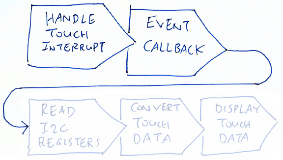
The complete flow from Touch Interrupt to Touch Data Display looks like this. The Rust Driver for PineTime Touch Controller is incomplete because we haven’t implemented Hit Testing to detect the graphic or text on the screen that’s tapped… So Hit Testing is coming next! (And if you wish to help out, drop me a note!)
PineTime Touch Controller fully functioning with Touch Interrupts
What’s Next?
Here are the other articles in the PineTime series…
Last week I declared that PineTime is perfect for teaching IoT… Today I’m walking the talk by applying PineTime to explain how a modern touchscreen works!
I built the Rust driver iteratively (pretty much in the same sequence we see in this article)… I really love the way Rust and Mynewt OS on PineTime make Embedded Experiments so fun and easy to execute!
As we have seen today, building the right IoT Software to run on today’s IoT Hardware can be challenging because of language issues. If you can read Chinese like me… Hang on to this precious skill! (Try watching 延禧攻略 or the Mandarin news)
I bet at this very moment, a non-native English reader is trying to read this English article… Struggling to understand “Ghost Station”, “dating profile”, “fish tank water” and their relevance to Touch Controllers.
IoT Education across all languages is needed now, more than ever. Here’s what I’m doing about it…
I hereby waive all copyright on my articles. You may reproduce my articles in any language, without asking for my permission.
Although a few of my articles have been translated into Chinese and Japanese… We can do better. Let’s share our IoT skills worldwide! 😀
References
Please refer to the “References” section at the end of the previous article “Sneak Peek of PineTime Smart Watch… And why it’s perfect for teaching IoT”
To run the code on a PineTime Smart Watch, follow the instructions in the section “Programming the PineTime Smart Watch” of the above article.
The updated code may be found in
the pinetime branch of this repository, which is the same branch
used in the previous article…