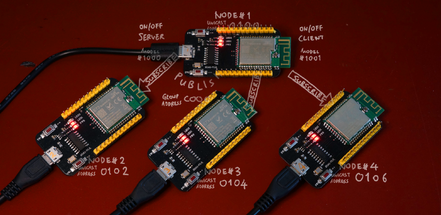
Bluetooth Mesh with four EBYTE E73-TBB Development Boards based on Nordic nRF52832 Microcontroller
Bluetooth Mesh with nRF52 and Apache Mynewt
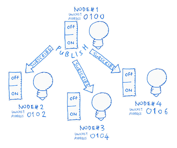
Suppose we have four light bulbs in our home, each with its own on/off switch…
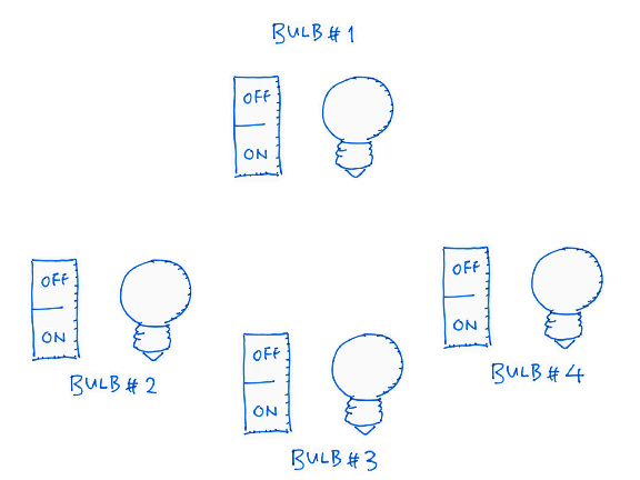
Let’s make them smart… With Wireless Remote Control!
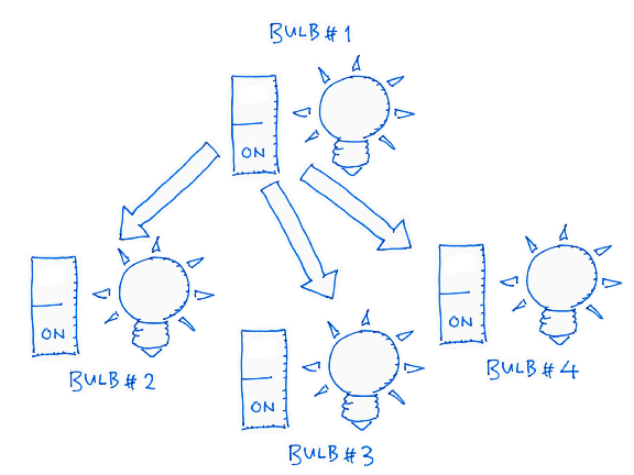
Flipping the on/off switch of the first bulb should switch the other bulbs on and off. So the first on/off switch acts like a Master On/Off Switch for our entire home.
How shall we implement this?
We could do this with WiFi… Assuming that we have good WiFi coverage at every corner of our home. There’s a simpler solution… Bluetooth Mesh!
With Bluetooth Mesh there’s no need for a shared network like WiFi. Each node in the mesh may relay messages to other nodes in the mesh. So our bulbs could relay on/off messages to one another all around the house… Maybe outside the house too! (Think Christmas lights)
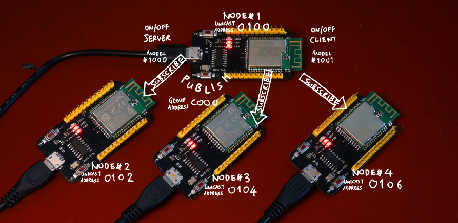
That’s exactly what I have created here… A Master On/Off Switch for four nRF52 wireless nodes, connected via Bluetooth Mesh…
Master On/Off Switch for four nRF52 wireless nodes, connected via Bluetooth Mesh. The nRF52 boards are powered by a USB charger connected to the Micro USB ports.
Now Bluetooth Mesh is incredibly complicated and difficult to grasp… So I’ll explain it in small pieces (while I’m learning it myself!)
In this tutorial we’ll set up the above nRF52 mesh network, step by step, without any coding! During the setup we’ll encounter mesh concepts (like Models, Elements, Groups, …) We’ll learn them only when we meet them. (The advanced concepts shall be deferred to the next tutorial.)
The complete source code may be
found in the mesh branch of this repository…
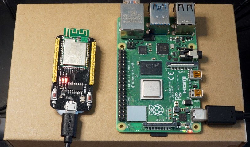
EBYTE E73-TBB Development Board (based on nRF52) provisioned into a Bluetooth Mesh by running meshctl on Raspberry Pi 4
Hardware Needed
Get ready the following hardware to build our Bluetooth Mesh…
- One or more nRF52 Development Boards (I used the $8 EBYTE E73-TBB Development Board)
- ST-Link v2 USB Programmer (under $2, check my article)
- Raspberry Pi 3 or 4 (Older models may work too. I tested on Pi 4)
This is the same setup that I have explained in my previous article “Coding nRF52 with Rust and Apache Mynewt on Visual Studio Code”
Install Raspberry Pi
To set up the Bluetooth Mesh network, we need to use a Raspberry Pi to talk to the nRF52 boards wirelessly and add them one by one to the mesh… This is called Mesh Provisioning.
We’ll be using a tool called
meshctl to perform the provisioning on our Pi. (Why Pi? Because
meshctl doesn’t run on Windows and macOS.) meshctl is part of the open-source BlueZ suite of Bluetooth utilities.
Follow
the instructions here to install meshctl on your Raspberry
Pi. (Yes BlueZ is preinstalled on Pi but it lacks the meshctl
utility.)
Unfortunately we need to rebuild
the Pi kernel (as explained in the instructions)… Because meshctl needs AEAD-AES_CCM encryption, which runs as a secure
service in the kernel. This may take an hour or more to complete.
Install nRF52 Boards
Follow
the instructions here to flash the bootloader and sample application (NimBLE blemesh_models_example_2)
to your nRF52 boards. If the boards have been previously provisioned, click Terminal → Run Task → Erase Flash to erase the previous provisioning
info (stored in Flash ROM), then re-flash the bootloader and application.
Connect the first nRF52 board to
your computer via ST-Link. Start a debug session, click Continue
for all breakpoints. Observe the Console Log.
Keep your nRF52 Board close to your Raspberry Pi. Remember we’ll be doing the Mesh Provisioning wirelessly, over the crowded 2.4 GHz airwaves, so the provisioning works better when the devices are close together.
Provision First nRF52 Board
On our Raspberry Pi, enter these commands…
cd ~
cp bluez-5.50/mesh/local_node.json bluez-5.50/mesh/prov_db.json .
The cp command is only needed for provisioning the
first nRF52 board. What’s prov_db.json?
As we provision the mesh, meshctl will remember the details of our mesh… security keys, node
addresses, services in each nodes. These details will be saved into prov_db.json when each nRF52 node has been provisioned.
When we provision the second,
third, fourth, … nRF52 nodes, meshctl will read the mesh details
from prov_db.json so that it can add the nodes to be existing
mesh.
Now enter…
meshctl
Press Enter to see the [meshctl]#
prompt.
Our first nRF52 board is powered
on and ready to be provisioned… But meshctl has no clue how to
contact the board. Let’s give meshctl some guidance. Enter…
discover-unprovisioned on
This enables meshctl to discover any nodes that have not been provisioned…
Because unprovisioned nodes will broadcast their unprovisioned status to the airwaves (like a beacon).
In a while we’ll see this…
SetDiscoveryFilter success
Discovery started
Adapter property changed
[CHG] Controller DC:A6:32:2C:70:F1 Discovering: yes
  Mesh Provisioning Service (00001827-0000-1000-8000-00805f9b34fb)
   Device UUID: dddd0000000000000000000000000000
   OOB: 0000
[NEW] Device 09:10:C7:7C:DC:8F nimble-mesh-node
Our nRF52 board has been found! (If you don’t see this, move the nRF52 board closer to your Raspberry Pi)
Take note of the discovered
Device UUID dddd0000000000000000000000000000
Now we tell meshctl to provision this new node into our mesh. Enter…
provision dddd0000000000000000000000000000
If the provisioning goes well we should see this prompt…
Request ASCII key (max characters 6)
[mesh] Enter key (ascii string):
(Move the devices closer if you don’t see this)
This is a security check, to be sure that we are authorised to provision the node into the mesh. How do we find the secret key?
Switch over to the Visual Studio Code Debugger. Check the Console Log of our nRF52 board. We should see this message…
OOB String: RWLDWY
Go back to meshctl and enter exactly what you see next to OOB String (assuming
that you see RWLDWY)…
RWLDWY
Our provisioning is almost done!
Unicast Address
In seconds we should see the provisioning completed for our first mesh node…
Provision success. Assigned Primary Unicast 0100
On the Console Log of our nRF52 board we should see a matching message…
Local node provisioned, primary address 0x0100
What is this
Primary Unicast Address 0100?
Each node in our mesh will be
assigned a permanent address (in hexadecimal): 0100, 0102, 0104, 0106, … Since this is the first node, it’s assigned address 0100.
(What happened to 0101, 0103, …? I’ll explain in
the next tutorial)
This is called a Unicast Address, the direct address for the node… “Got something to say to this node? Call this direct number!”
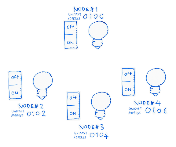
Unicast Addresses for our Mesh Nodes
(Later we’ll see a different kind of address, a Group Address, that we may use to contact multiple nodes.)
Unicast Addresses are stored in
prov_db.json of our Raspberry Pi, also in the Flash ROM of the
nRF52 board (so the board won’t forget its assigned address).
If we ever need to re-provision
this node, we will have to run the Terminal → Run Task → Erase Flash command in Visual Studio Code to
erase the Unicast Address stored in the Flash ROM.
Configure the nRF52 Node
Now that we have provisioned the
node, let’s configure it. Enter into meshctl…
menu config
meshctl shall now dial up the new node at 0100 to give it a makeover. Enter…
target 0100
Let’s talk secrets. We can’t let
anyone manipulate our nodes, so we need to lock our nodes with a common secret Application Key or AppKey. Enter into meshctl…
appkey-add 1
Where 1 refers to the AppKey with index 1 from prov_db.json…
"appKeys":[
    {
      "index":0,
      "boundNetKey":0,
      "key":"4f68ad85d9f48ac8589df665b6b49b8a"
    },
    {
      "index":1,
      "boundNetKey":0,
      "key":"2aa2a6ded5a0798ceab5787ca3ae39fc"
    }
  ],
Generic On/Off Model, Server and Client
Now that we have loaded the AppKey, we are ready to lock our new node, part by part. Recall that we have two parts in our nRF52 node, the Switch and the Light…
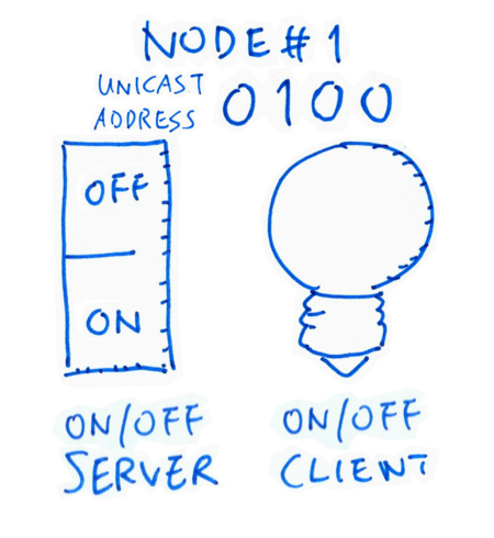
In Bluetooth Mesh lingo this setup is called a Generic On/Off Model… We only remember the on/off state of the Switch and the Light.
The Switch controls the Light. So we call the Switch the Server, and we call the Light the Client.
Let’s lock the Switch, a.k.a.
On/Off Server. Enter the into meshctl…
bind 0 1 1000
This locks Element #0 using AppKey #1 (remember
our key?) for Model #1000.
Today we won’t be going combing
the entire Periodic Table… We’ll limit ourselves to a single Element: Element #0. (More about Elements next time)
Model #1000… Wow have we got thousands of Models squeezed into our tiny
workspace? (Like Project Runway?)
No, each Model Server/Client is
designated a fixed number by the creators of Bluetooth Mesh… Model #1000 is the official designation for Generic
On/Off Server a.k.a. BT_MESH_MODEL_ID_GEN_ONOFF_SRV
a.k.a. The Switch.
So this command locks the Switch with our AppKey. Once it’s locked, others may access the Switch securely, as long as they got the right AppKey.
In case you’re curious about the
other Model numbers: https://github.com/apache/mynewt-nimble/blob/master/nimble/host/mesh/include/mesh/access.h
For completeness, let’s lock and
expose our Light as well. Enter into meshctl…
bind 0 1 1001
This locks (and exposes) Element
#0 (only one element today) with AppKey #1 (yes the same) for Model #1001.
If we ask the creators of
Bluetooth Mesh, they’ll say that Model #1001 is the Generic On/Off Client alias BT_MESH_MODEL_ID_GEN_ONOFF_CLI alias The Light. So our Light has
been locked for secure access.
Generic Level Model, Server and Client
Our Switch and Light are ready to
be used! But let’s strut some more fabulous Models down our tiny runway. Enter into meshctl…
bind 0 1 1002
bind 0 1 1003
Same thing as before, but Model
#1002 is a Generic Level Server
(BT_MESH_MODEL_ID_GEN_LEVEL_SRV) and Model #1003 is a Generic Level Client (BT_MESH_MODEL_ID_GEN_LEVEL_CLI).
What’s a Generic Level? Why not just use Generic On/Off?
Sure… if we’re happy with binary states like On and Off, Black and White. But if we’re into Fifty Shades Of Grey (think dimmable lights), then we need a Generic Level to express levels of brightness (“50% brightness for this light”)
So many Models… Will this runway ever end?
Yes… eventually. Our sample
application defines a number of Bluetooth Mesh Models. But today we’ll learn only the simplest On/Off
Model. The Models are defined here: https://github.com/lupyuen/stm32bluepill-mynewt-sensor/blob/mesh/apps/my_sensor_app/src/device_composition.c#L2691-L2767
Publish and Subscribe
Recall from the video that we had a Central Switch controlling the other Lights wirelessly. How did the on/off state of our Central Switch propagate through the airwaves to the other Lights?
With a little Bluetooth Mesh magic called Publish and Subscribe!
Our Central Switch publishes its on/off state to the mesh. Then each Light subscribes to this on/off state to receive updates.
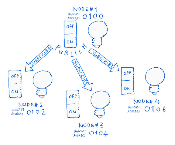
Let’s understand this better by
doing a simple Publish and Subscribe. Enter into meshctl…
sub-add 0100 c000 1000
This creates a new Subscription
that will monitor updates to Unicast Address 0100 (our first
node). The Subscription will listen to Group Address c000 for
updates to Model #1000 (our Switch, the Generic On/Off Server).
What is this Group
Address c000?
In a while we’ll see that c000 is the Group Address that our Switch will use to publish on/off
updates.
Yes we have only one node, but it’s perfectly OK for the node to subscribe to itself. This enables the Light inside our node to subscribe to updates from the Switch that belongs to the same node. Flip the Switch, and the Light changes!
Let’s create another Subscription
to reinforce the Publish/Subscribe concept. Enter into meshctl…
sub-add 0100 c000 1002
This creates a new Subscription
that will monitor updates to Unicast Address 0100 (same node).
The Subscription will listen to Group Address c000 (same
address).
But this time we’re listening for
updates to Model #1002 (our Generic Level Server). Why would we
do this? So that the first node can propagate its Brightness Level to other nodes and achieve
all-round Fifty Shades of Grey (actually 65,536 shades).
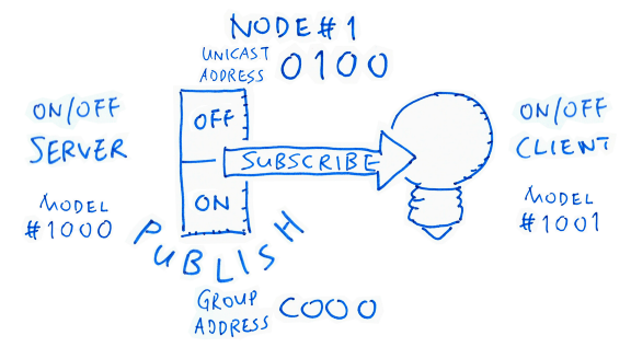
Publish On/Off Status and Brightness Level
To complete the node
configuration let’s publish the On/Off Status. Enter into meshctl…
pub-set 0100 c000 1 0 5 1001
This creates a new Publication
that will notify its subscribers of updates to Unicast Address 0100 (the first node).
The updates shall be published to
Group Address c000 (remember this?). We may pick any Group
Address from c000 to ffff.
For security, we shall lock the
Publication with AppKey #1. The numbers 0 and 5 refer to the Publish
Period and Publish Retransmit Count (which we won’t cover today, but retransmits are really helpful).
Updates to the On/Off Status
shall be channelled to the Light, which is Model #1001 (our
Generic On/Off Client).
Lastly we publish the Brightness Level by entering…
pub-set 0100 c000 1 0 5 1003
Everything is the same, except
for Model #1003, the Generic Level Client that can receive
updates for 65,536 levels of brightness. (No more shady business today I promise!)
Test Publish and Subscribe
Enough provisioning and
configuring for our first node… Let’s test it! In meshctl enter…
back
menu onoff
target 0100
Remember that Generic On/Off is a
standard Model in Bluetooth Mesh. So meshctl will let us send
On/Off commands easily (via the onoff menu) to test our node.
As for the target… Which node shall we be testing? 0100 of course. Enter into meshctl…
onoff 0
This sets the On/Off Client Status to Off. The nRF52 application has been programmed to show the On/Off Client Status on the LED, so this flips the LED Light off. (Check the LED!)
Verify the On/Off Client Status by entering…
get
You should see value 0…
On Off Model Message received (1) opcode 8204
00
The nRF52 Console Log should show the LED Light flipping off…
power-> 0, color-> 0
Now watch what happens when you enter this…
onoff 1
get
Yes we are now flipping our nRF52 LED Light on and off wirelessly via our Raspberry Pi!
Try the same thing you see in the video at the top of this article… Press the buttons on the nRF52 board one at a time. Pressing the first button should flip the Light on, pressing the second button should flip the Light off.
The nRF52 application has been programmed such that pressing the buttons will set the on/off state of the On/Off Server (the Master Switch).
Remember that the LED Light is an On/Off Client that subscribes to the server… Hence the LED Light will also flip on and off.
This is Publish and Subscribe in action!
When we have finished testing,
exit meshctl by entering…
exit
Always exit meshctl before powering down any mesh node. Otherwise meshctl may hang while attempting to exit. (And you would need to
reboot your Raspberry Pi to release the locked Bluetooth driver)
To connect to the mesh network in
future, just launch meshctl and enter connect. All the provisioning details are stored in prov_db.json,
so meshctl knows exactly how to connect to the mesh. You may
power up the nRF52 board by disconnecting it from ST-Link and connecting a USB Charger to the Micro
USB port. Here’s a video demo…
Connecting to Bluetooth Mesh with meshctl. The nRF52 board is powered by a USB charger connected to the Micro USB port.
Provision, Configure and Test Node #1
Here’s a recap of the steps to provision, configure and test our first mesh node…
Provision, configure and test Node #1. From https://github.com/lupyuen/stm32bluepill-mynewt-sensor/blob/mesh/logs/provision-mesh.log
Here are my meshctl Log and Console Log for provisioning
the first node.
Let’s complete the setup for the remaining three nodes in our mesh…
Our Bluetooth Mesh with four nodes
Provision, Configure and Test Nodes #2, 3 and 4
The mesh demo application works with two or more nodes. Here are the steps for setting up the second, third and fourth nodes.
Follow the instructions in this article (“Flash The Firmware”) to flash our application to the second, third and fourth nRF52 boards.
Before setting up the second mesh node, stop the Visual Studio Code Debugger and disconnect the first node from ST-Link.
Connect the second node to
ST-Link and start the debugger. Press Continue at all
breakpoints. Don’t worry, the mesh will run fine without the first node, because meshctl has all the mesh details in prov_db.json
Enter these commands to provision, configure and test Node #2…
Provision, configure and test Node #2. From https://github.com/lupyuen/stm32bluepill-mynewt-sensor/blob/mesh/logs/provision-mesh2.log
Here are my meshctl Log and Console Log for provisioning
the second node.
Now this looks odd… Can you spot
the problem? (Remember that 0102 is the Unicast Address for Node
#2)
sub-add 0102 c000 1000 — Subscribe to On/Off Updates at Group
Address c000 — Publish On/Off
Updates at Group Address
pub-set 0102 c000 1 0 5 1001c000
Within Node #2 it makes sense to publish and subscribe On/Off updates locally, so that pressing the buttons on Node #2 will flip the Node #2 LED Light on and off.
But Group Address
c000 is already used by Node #1 to publish
On/Off updates for the buttons on Node #1!
Hence when we press the buttons on Node #2, the updates will be propagated to Node #1… The buttons on Node #2 also work as the Master Switch!
This fix for this is… left as an exercise for the reader. For now we’re using a simple setup that has the unintended effect of making all nodes the Master Switch. Now for Node #3…
Stop the debugger, disconnect
Node #2 from ST-Link, connect Node #3 to ST-Link and start the debugger. Press Continue at all breakpoints.
Enter these commands to provision, configure and test Node #3…
Provision, configure and test Node #3. From https://github.com/lupyuen/stm32bluepill-mynewt-sensor/blob/mesh/logs/provision-mesh3.log
Here are my meshctl Log and Console Log for provisioning
the third node. Finally for Node #4…
Stop the debugger, disconnect
Node #3 from ST-Link, connect Node #4 to ST-Link and start the debugger. Press Continue at all breakpoints.
Enter these commands to provision, configure and test Node #4…
Provision, configure and test Node #4. From https://github.com/lupyuen/stm32bluepill-mynewt-sensor/blob/mesh/logs/provision-mesh4.log
Here are my meshctl Log and Console Log for provisioning
the fourth node.
Here’s my prov_db.json
after provisioning all four nodes. I strongly recommend that you backup your copy of prov_db.json
located at the pi home directory of your Raspberry Pi… Because
the microSD Card can get corrupted so easily. (Happened a few times while I was writing this)
If we need to re-provision any of
the nodes, remember to erase the Flash ROM with the Terminal → Run Task → Erase Flash command in Visual Studio Code.
And we’re done! Disconnect the fourth node from ST-Link. Power up all four nodes by connecting a USB Charger to the Micro USB port. Press the buttons on Node #1 like in this video… And the LED Light on other nodes will magically flip on and off!
Master Light Switch accomplished with Bluetooth Mesh!
What’s Next?
This is the second article in my nRF52 series of articles. The first article is here: “Coding nRF52 with Rust and Apache Mynewt on Visual Studio Code”
Bluetooth Mesh looks really useful for the upcoming PineTime Smart Watch (also based on nRF52). So you can discover which of your friends and family members are in close range (assuming they are wearing the watch too).
Can’t wait to install Bluetooth Mesh on PineTime! Here’s my review…
You may have noticed that the nRF52 application includes the Embedded Rust runtime. I’ll be using Rust Macros to eliminate the repetitive C code used for building Bluetooth Mesh.
Bluetooth Mesh programming doesn’t need to be so complicated… Stay tuned for the simpler, safer Rust version!
References
Our sample application comes from the open-source Apache NimBLE project, which is described here…
Here’s an excellent tutorial on Bluetooth Mesh based on Zephyr embedded OS…
Another tutorial based on nRF52 and Nordic SoftDevice…
Bluetooth SIG has a series of high-level articles about Bluetooth Mesh…
The official Bluetooth Mesh specifications are here…