
Debugging nRF52 with a Raspberry Pi 4 running VSCode and OpenOCD with SWD over SPI at 31 MHz
OpenOCD on Raspberry Pi: Better with SWD on SPI
Sneaky tricks to align stray bits into proper bytes
The setup that we see above… Debugging nRF52 with a Raspberry Pi running VSCode and OpenOCD… Was impossible just a week ago!
OpenOCD connects to nRF52 for flashing and debugging by running Arm’s SWD protocol over GPIO Bit Banging. OpenOCD was sending data to nRF52 one bit at a time… Works fine when OpenOCD is the only task running, not when it’s sharing the CPU with VSCode and other interactive tasks!
That’s because multitasking skews the precise timing that’s needed by OpenOCD to send each bit correctly.
Instead of sending data over GPIO one bit at a time, what if we could blast out the data over Raspberry Pi’s SPI interface?
SPI (Serial Peripheral Interface) is implemented as a kernel mode driver with interrupts, so it runs with high CPU priority. Raspberry Pi’s Broadcom microcontroller supports Bidirectional SPI (31 MHz) with precise clocking and buffering. Why not use SPI for SWD?
This article explains how we did that… By overcoming some interesting bitwise challenges. The SWD protocol enables OpenOCD to flash and debug firmware, by reading and writing the debugging registers on our Arm CPU. We’ll study the SWD Register Read/Write operations in a while…
Build and Test OpenOCD with SPI
UPDATE: There’s an easier way to build openocd-spi
and use it to flash firmware… Check out pinetime-updater
The SPI version of OpenOCD is here…
https://github.com/lupyuen/openocd-spi
To build and test on Raspberry Pi Zero, 1, 2, 3 or 4…
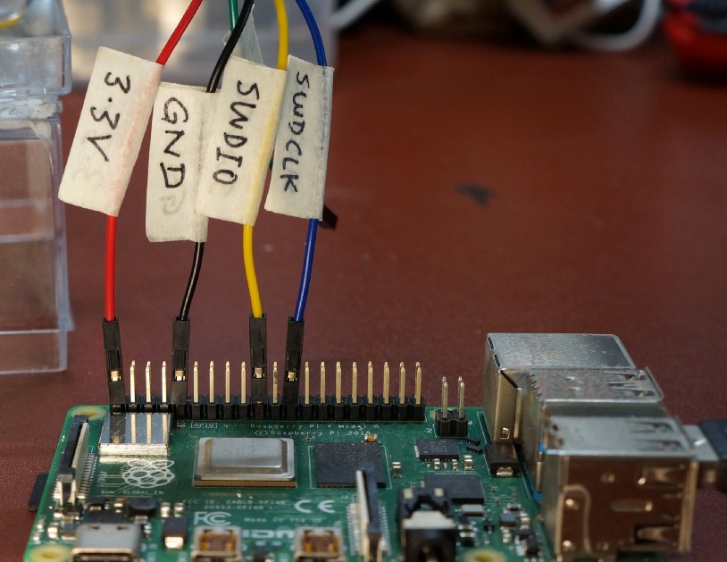
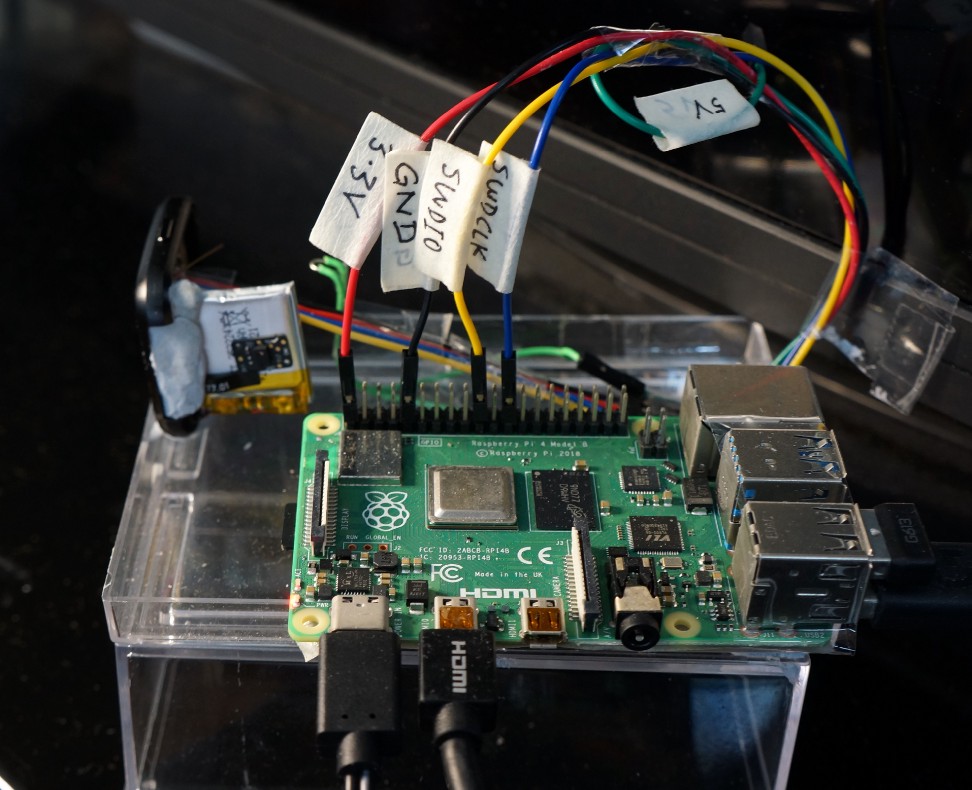
1️⃣ Connect PineTime / nRF52 to the SPI port on Raspberry Pi…
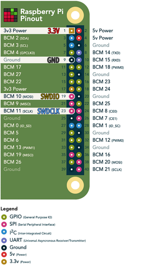
Connecting Raspberry Pi to PineTime / nRF52. Based on https://pinout.xyz/
Connecting Raspberry Pi to PineTime / nRF52
2️⃣ Enable the SPI interface on Raspberry Pi…
sudo raspi-config
Select
Interfacing Options → SPI → Yes
3️⃣ Download and build the modified OpenOCD…
cd ~
git clone https://github.com/lupyuen/openocd-spi
cd openocd-spi
./bootstrap
./configure --enable-sysfsgpio --enable-bcm2835spi --enable-cmsis-dap
make
The
modified OpenOCD executable is now at openocd-spi/src/openocd
If you see this error…
Cloning into 'openocd-spi/jimtcl'...
fatal: unable to access 'http://repo.or.cz/r/jimtcl.git/': Recv failure: Connection reset by peer
fatal: clone of 'http://repo.or.cz/r/jimtcl.git' into submodule path '/private/tmp/aa/openocd-spi/jimtcl' failed
It means
that the sub-repository for one of the dependencies jimtcl is
temporarily down. You may download the pre-built openocd-spi
binaries from this link.
4️⃣ If
you’re using pinetime-rust-mynewt downloaded from
this article…
Edit the
OpenOCD scripts located at pinetime-rust-mynewt/scripts/nrf52-pi…
flash-app.sh, flash-boot.sh, flash-unprotect.sh
Change
the openocd folder to openocd-spi like this…
$HOME/openocd-spi/src/openocd \
    -s $HOME/openocd-spi/tcl \
    -f scripts/nrf52-pi/swd-pi.ocd \
    -f scripts/nrf52/flash-app.ocd
Run these scripts to unprotect the flash ROM, flash the bootloader and flash the application via SPI…
cd ~/pinetime-rust-mynewt
scripts/nrf52-pi/flash-unprotect.sh
scripts/nrf52-pi/flash-boot.sh
scripts/nrf52-pi/flash-app.sh
More details may be found the article “Build and Flash Rust+Mynewt Firmware for PineTime Smart Watch” under the section “Remove PineTime Flash Protection”
5️⃣ If
you prefer to write your own OpenOCD scripts (instead of using pinetime-rust-mynewt)…
Here’s a sample OpenOCD script and shell script that you may adapt for flashing…
OpenOCD
Script: flash-boot.ocd
and swd-pi.ocd
Shell Script:
$HOME/openocd-spi/src/openocd \
    -s $HOME/openocd-spi/tcl \
    -f swd-pi.ocd \
    -f flash-boot.ocd
Unlike
GPIO, the SPI interface doesn’t require sudo access.
Make sure
that you select bcm2835spi as the OpenOCD interface (in swd-pi.ocd).
# Select the Broadcom SPI interface for Raspberry Pi (SWD transport)
interface bcm2835spi # Set the SPI speed in kHz
bcm2835spi_speed 31200  # 31.2 MHz
bcm2835spi accepts one parameter bcm2835spi_speed, the SPI speed in kHz. bcm2835spi_speed defaults to 31200 (31.2 MHz). Check this for the list of supported SPI
speeds
Run the above scripts to flash your device.
6️⃣ You should see this message if you’re using the 31 MHz SPI version of OpenOCD (instead of the old GPIO version)…
Info : BCM2835 SPI SWD driver
Info : SWD only mode enabled
Info : clock speed 31200 kHz
7️⃣ If the flashing over SPI is successful, you should see…
** Programming Started **
Info : nRF52832-QFAA(build code: E1) 512kB Flash, 64kB RAM
Warn : Adding extra erase range, 0x0003da78 .. 0x0003dfff
** Programming Finished **
** Verify Started **
** Verified OK **
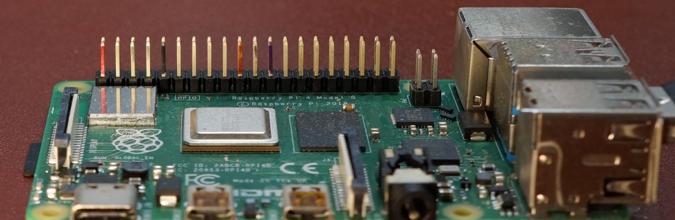
Here’s a tip: Colour the Raspberry Pi pins with a marker (one side only) so that we remember which pin to connect
💎 The Bidirectional SPI we’re using on Raspberry Pi is slightly different from the normal SPI interface… Normal SPI runs on 3 data pins: SCLK (Clock), MOSI (Host → Target), MISO (Target → Host). The Broadcom microcontroller on Pi supports SPI with 2 data pins, by merging the MOSI and MISO pins. Hence it’s called “Bidirectional SPI”. It’s pin-compatible with SWD, which also uses 2 data pins.
Will SWD over SPI work on other microcontrollers besides Broadcom? Possibly not… I wasn’t able to find a similar Bidirectional SPI mode for Rockchip RK3328, for instance. Bidirectional SPI mode is sometimes named MOMI or SISO mode.
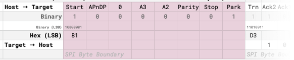
SWD Read Operation
OpenOCD flashes and debugs firmware by reading and writing the debugging registers on our Arm CPU. Let’s look at the reading of registers…
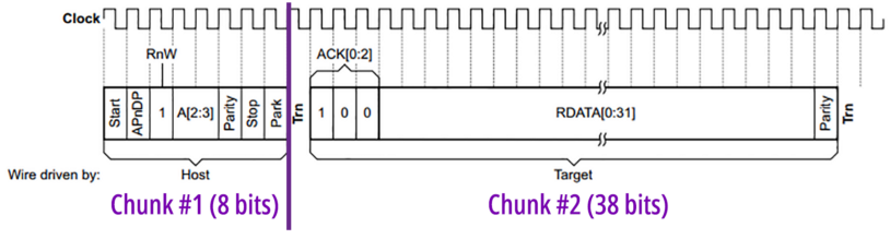
For Raspberry Pi to read an SWD Register on nRF52, we perform an SWD Read Operation like this (Raspberry Pi is the host, PineTime/nRF52 is the target)…
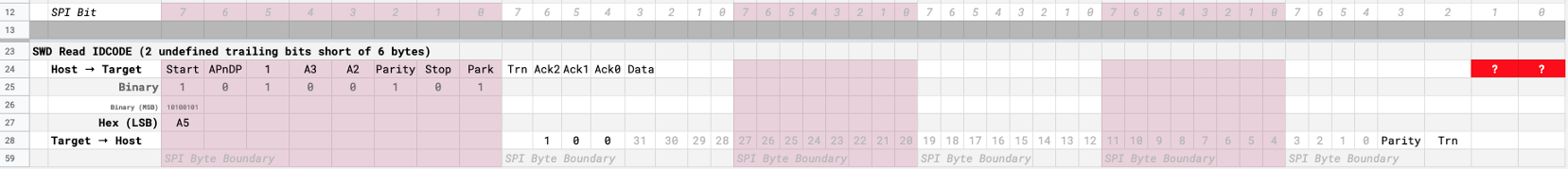
SWD Read Operation with 2 undefined trailing bits. From https://docs.google.com/spreadsheets/d/12oXe1MTTEZVIbdmFXsOgOXVFHCQnYVvIw6fRpIQZybg/edit#gid=0
Here we
are reading the IDCODE (Identification Code) Register, which
identifies the Arm Debug Interface (0x2ba01477 for nRF52).
IDCODE is Register #0 (in Read Mode), so we set A2 and A3 (bits 2 and 3 of the register number) to 0.
Pi → nRF52: 8 bits…
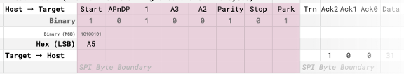
From Pi to nRF52
Pi sends
0xA5 (least significant bit first) to nRF52. That’s followed
by Trn, the Turnaround Bit. This bit gives 1 clock cycle of
breathing space whenever we flip the transmission from Pi to nRF52 and back. The value of Trn doesn’t matter.
nRF52 → Pi: 38 bits (including turnaround)…

From nRF52 to Pi
nRF52
responds with the Acknowledgement 100 (which means OK).
Followed by 32 bits of data (the value of Register IDCODE), a Parity bit, and another Turnaround
Bit.
Now let’s see whether Raspberry Pi’s SPI interface will allow us to send and receive this kind of data.
Missing: 2 bits…

From nRF52 to Pi and back
Count the bits for the entire SWD Read Operation (look at the red blocks)… It has 46 bits, which is 2 bits short of 6 whole bytes.
Also the last byte is split across Pi and nRF52… nRF52 sends 5 bits, then Turnaround, then Pi is supposed to send 2 bits from the next read/write operation!
Since Raspberry Pi’s SPI interface can only send and receive whole bytes (not bits)… We have a problem with the last 2 stray bits!
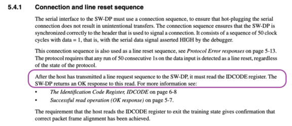
nRF52 gets utterly confused after the SWD Read Operation. Only way to fix this? Reset the SWD connection and resynchronise by resending the JTAG-To-SWD Sequence.
Sending the JTAG-To-SWD Sequence to reset SWD connection. From https://github.com/lupyuen/openocd-spi/blob/master/src/jtag/swd.h
Yes our SWD flashing may slow down when we reset the SWD connection after every SWD Read Operation… But we are now running the SWD connection over SPI at a speedy 31 MHz! This compensates for the reset transmission, so the overall SWD flashing is still fast.
After every SWD Read Operation, send the JTAG-To-SWD Sequence to reset SWD connection. From https://github.com/lupyuen/openocd-spi/blob/master/src/jtag/drivers/bcm2835spi.c
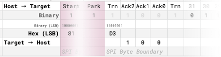
Throwaway SWD Read Operation
For SWD to work over SPI, we need to reset the SWD connection after every SWD Read Operation… Just send the JTAG-To-SWD Sequence! But there’s a catch: We MUST read IDCODE after sending the JTAG-To-SWD Sequence…
Resetting the SWD connection. From ARM® Debug Interface v5 Architecture Specification https://github.com/MarkDing/swd_programing_sram/blob/master/Ref/ARM_debug.pdf
See the problem here? We need to reset after reading a register… And yet we need to read a register (IDCODE) after resetting!
The snake eats its own tail! To break the snake, we use a sneaky way to read IDCODE after resetting, the Throwaway Way…
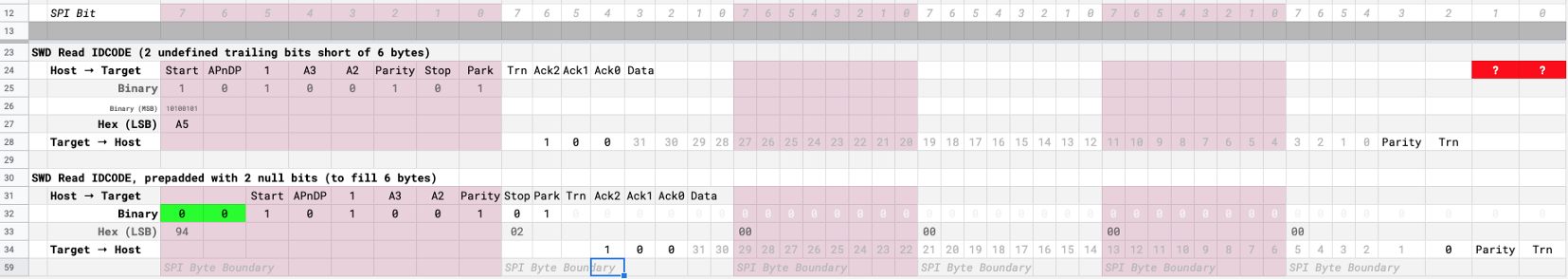
Read IDCODE Operation: Normal operation (above) and Throwaway operation (below). From https://docs.google.com/spreadsheets/d/12oXe1MTTEZVIbdmFXsOgOXVFHCQnYVvIw6fRpIQZybg/edit#gid=0
Notice that we slide the entire Read IDCODE Operation two bits to the right… Inserting two null bits in front.
Will nRF52 accept the two null leading bits sent by Pi? Yes because all SWD
Read/Write Operations must start with 1. So it’s always OK for
Pi to send null bits before and after every SWD Read/Write Operation.
For a normal SWD Read Operation (that’s not byte-aligned and hence problematic)…
Pi → nRF52: 8 bits (A5), followed by…
nRF52
→ Pi: 38 bits (Data + Parity + Turnaround)
Total 46 bits, not byte-aligned, no good. For our special Throwaway version with two prepadded null bits…
Pi → nRF52: 48 bits (94 02 00 00 00 00), followed by…
nRF52 → Pi: 0 bits
Total 48 bits, byte-aligned, all good! So the next SWD Read or Write Operation may be sent, perfectly aligned to the byte. (If the next operation is SWD Read, we’ll have to read the register, reset and read IDCODE again)
But it sounds like Pi is yakking away over the entire SWD Read Operation, not really listening to nRF52 (and getting the value of IDCODE)?
That’s perfectly fine… We don’t really care about the value of IDCODE anyway. We are only reading IDCODE because Arm said so.
Thus in
the SPI implementation of SWD, we see this special Throwaway Read IDCODE (94 02 00 00 00 00) that’s sent after every SWD connection reset in
spi_transmit_resync().
To give sufficient clock cycles for nRF52 to do its job, we insert a null byte before and after the
Throwaway Read IDCODE: 00 94 02 00 00 00 00 00
Reset SWD Connection with Throwaway Read IDCODE. From https://github.com/lupyuen/openocd-spi/blob/master/src/jtag/drivers/bcm2835spi.c
What’s the SWD Write ABORT Operation? We’ll learn in a while…
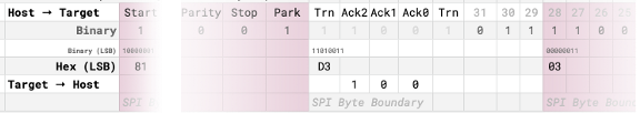
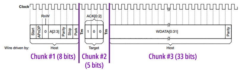
SWD Write Operation
For Raspberry Pi to write an SWD Register on nRF52, we perform an SWD Write Operation like this (Raspberry Pi is the host, PineTime/nRF52 is the target)…
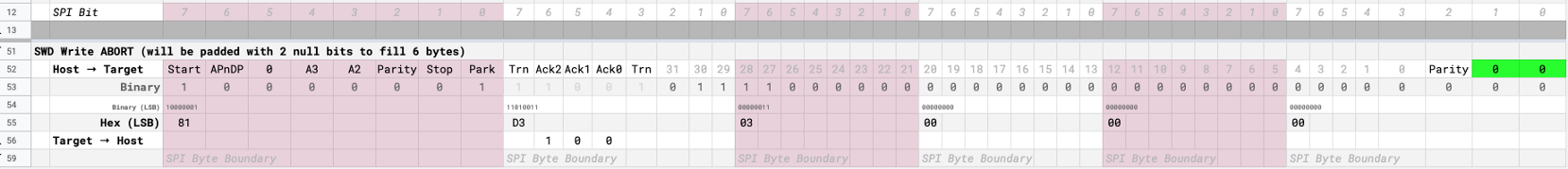
SWD Write Operation padded with 2 null bits. From https://docs.google.com/spreadsheets/d/12oXe1MTTEZVIbdmFXsOgOXVFHCQnYVvIw6fRpIQZybg/edit#gid=0
Here we
are writing the value 0x1E to the ABORT
Register. Whenever a SWD protocol error occurs during transmission (e.g. misaligned
bits), we need to clear the error by writing to the ABORT Register.
ABORT is
Register #0 (in Write Mode), so we set A2 and A3 (bits 2 and 3 of the register number) to 0.
Pi → nRF52: 8 bits…
From Pi to nRF52
Pi sends
0x81 (least significant bit first) to nRF52. That’s followed
by Trn, the Turnaround Bit.
nRF52 → Pi: 5 bits (including turnaround)…
From nRF52 to Pi
nRF52
responds with the Acknowledgement 100 (which means OK). and
another Turnaround Bit.
Pi → nRF52: 33 bits…

From Pi to nRF52
Pi sends 32 bits of data (the value to be written to Register ABORT) and a Parity bit.
Pi → nRF52: 2 bits (padding for byte alignment)…
From Pi to nRF52
For our SPI implementation, Pi sends an extra 2 null bits to make the entire operation byte-aligned: 6 whole SPI bytes. (Remember: It’s OK to insert extra null bits before and after SWD Read/Write Operations)
No misaligned bits for SWD Write Operations… Phew!
A Convenient Write Lie
Will SWD Write Operations work over SPI? SWD Write Operations are always byte-aligned, because we padded 2 null bits. But we have a funny Turnaround situation in the second byte of the SWD Write Operation…
From Pi to nRF52 and back
There are Two Turnarounds in the same byte!
nRF52 → Pi: 3 Acknowledgement Bits + 2 Turnaround Bits,
followed by…
Pi →
nRF52: 3 Data Bits
We can’t flip the direction of transmission within a single SPI byte transfer. So this fails for SPI! Thankfully we have another sneaky solution for this problematic second byte…
nRF52 → Pi: 0 bits, followed by…
Pi → nRF52: 3 Acknowledgement Bits + 2 Turnaround Bits + 3 Data Bits
Look familiar? This is the same trick as the Throwaway SWD Read Operation… We now throw away the 3 Acknowledgement Bits sent by nRF52 to Pi!
Instead
of Pi receiving the 3 Acknowledgement Bits from nRF52, Pi now sends 3 bits to
nRF52. Doesn’t matter whether they are 0 or 1, as long as it takes 3 clock cycles.
But that
means we won’t know whether the Write Acknowledgement is OK (100)!
Think about it… Is this Write Acknowledgement really useful? It happens before the data is written! Most of the time it’s used to indicate that the
Register ID (in A2 and A3) is valid.
Thus we
take a calculated risk and assume that the SWD Write Acknowledgement is always
OK. Our SPI code always lies and returns 100 to
OpenOCD.
Our SPI code always returns OK to OpenOCD for SWD Write Acknowledgement. From https://github.com/lupyuen/openocd-spi/blob/master/src/jtag/drivers/bcm2835spi.c
Will this cause problems when flashing the ROM of nRF52? Since we’re not checking the SWD Write Acknowledgement?
Here’s how we mitigate the risk of write failures: We always read and verify the ROM contents after flashing, like in this OpenOCD script…
program bin/targets/nrf52_my_sensor/app/apps/my_sensor_app/my_sensor_app.img verify 0x00008000
When we throw away the SWD Write Acknowledgement, we eliminate all Turnarounds. Our SWD Write Operation becomes really simple… Just send 8 whole bytes from Pi to nRF52!
Perfect for implementing SWD over SPI!
Hence to
write value 0x1E to the ABORT Register, Pi only needs to blast
out 6 bytes over SPI to nRF52: 81 d3 03 00 00 00
Sending 8 whole bytes from Pi to nRF52 for an SPI Write Operation. From https://github.com/lupyuen/openocd-spi/blob/master/src/jtag/drivers/bcm2835spi.c
Clear the Sticky Error Bits
We added
debug logs to the existing OpenOCD code in bitbang.c
to compare the old GPIO and new SPI implementations of the SWD protocol.
Remember we said earlier that every SWD Read Operation will be followed by an SWD connection reset that transmits two byte sequences to nRF52…
- JTAG-To-SWD Sequence
- Read IDCODE Sequence, prepadded with two null bits
Here’s what happens when we run OpenOCD with that setup…
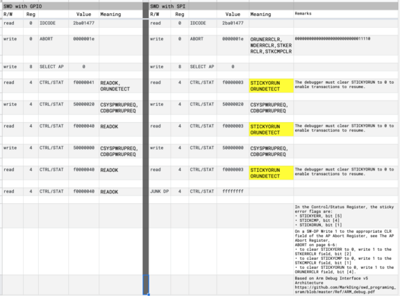
Comparing the logs from SWD over GPIO (left) with SWD over SPI (right). From https://docs.google.com/spreadsheets/d/12oXe1MTTEZVIbdmFXsOgOXVFHCQnYVvIw6fRpIQZybg/edit#gid=900511571
Both the
GPIO and SPI versions of OpenOCD are reading and writing to the same nRF52 registers: IDCODE, SELECT
AP, CTRL/STAT. But the value of the Control/Status Register (CTRL/STAT) is different for SPI: f0000003.
What’s
f0000003? Let’s key that into this spreadsheet to decode the Control/Status
value…
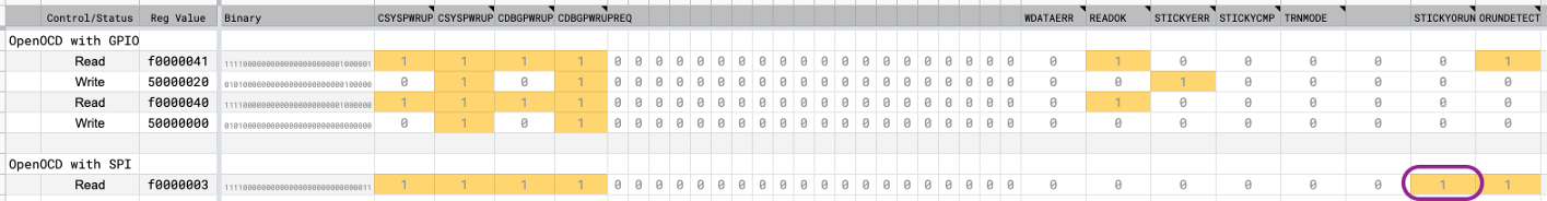
Control/Status Register Decoder: https://docs.google.com/spreadsheets/d/12oXe1MTTEZVIbdmFXsOgOXVFHCQnYVvIw6fRpIQZybg/edit#gid=2077834467
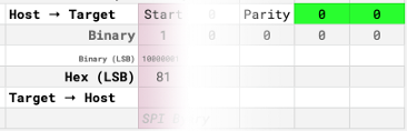
What’s the difference between the GPIO and SPI values for the Control/Status Register? SPI is experiencing the STICKYORUN error…

STICKYORUN flag in the Control/Status Register. From ARM® Debug Interface v5 Architecture Specification https://github.com/MarkDing/swd_programing_sram/blob/master/Ref/ARM_debug.pdf
This means that nRF52 has detected some overrun garbage on the SWD connection… Must be due to our misaligned SWD Read Operations!
This is a “Sticky” error… It sticks there forever until we do something to clear the error status. If we don’t clear the Sticky error status, all SWD operations will fail.
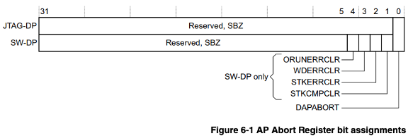
ABORT Register. From ARM® Debug Interface v5 Architecture Specification https://github.com/MarkDing/swd_programing_sram/blob/master/Ref/ARM_debug.pdf
The
solution: We write value 0x1E to the ABORT Register. That’s
binary 11110, which means that we are clearing all the errors: Overrun Error, Write Data Error, Sticky Error, Sticky Compare
Error.
In the
previous section we have learnt how to write value 0x1E to the
ABORT Register: By blasting out over SPI 81 d3 03 00 00 00
When shall we write to the ABORT Register to clear the errors?
Remember that Pi has become extremely negligent to nRF52… Pi has thrown away so much feedback and acknowledgement from nRF52! We don’t know exactly when nRF52 is having issues. But since…
- The errors are caused by the misaligned SWD Read Operation
- And we always reset the SWD connection after every SWD Read Operation (except the Throwaway Read IDCODE)…
Let’s write to the ABORT Register and clear the errors at every SWD connection reset.
Clearing the errors at every SWD connect reset by writing to ABORT. From https://github.com/lupyuen/openocd-spi/blob/master/src/jtag/drivers/bcm2835spi.c
With this fix, SWD over SPI works perfectly!
Inject SPI into OpenOCD Bit Bang
We have SWD Read and Write Operations working fine over SPI, and we have forcibly fixed all the SWD errors indirectly caused by SPI. Now let’s inject this SPI code into the OpenOCD code.
OpenOCD
calls bitbang_exchange() in bitbang.c
whenever it needs to transmit or receive a chunk of bits in a fixed direction. OpenOCD calls bitbang_exchange() two times for every SWD Read, three times for
every SWD Write…
SWD Read: bitbang_exchange() called for two chunks of bits.
From https://github.com/MarkDing/swd_programing_sram/blob/master/Ref/ARM_debug.pdf
SWD Write: bitbang_exchange() called for three chunks of bits.
From https://github.com/MarkDing/swd_programing_sram/blob/master/Ref/ARM_debug.pdf
bitbang_exchange() is called by OpenOCD like this…
Here’s
the existing code for bitbang_exchange() that transmits and
receives chunks of bits over GPIO…
From https://github.com/lupyuen/openocd-spi/blob/master/src/jtag/drivers/bitbang.c
And
here’s the modification we made for bitbang_exchange() to
transmit and receives chunks of bits over SPI…
From https://github.com/lupyuen/openocd-spi/blob/master/src/jtag/drivers/bitbang.c
Which
simply forwards the call to our new function spi_exchange() in
bcm2835spi.c.
From https://github.com/lupyuen/openocd-spi/blob/master/src/jtag/drivers/bcm2835spi.c
Because
spi_exchange() is called with chunks of bits, we use the offset and bit_cnt
parameters to figure out whether this chunk came from an SWD Read or Write Operation, and which
chunk in that operation…
Deducing the chunk by offset and bit_cnt. From https://github.com/lupyuen/openocd-spi/blob/master/src/jtag/drivers/bcm2835spi.c
(Yeah this chunk handling smells bad… We should inject the SPI code into bitbang_swd_read_reg() and bitbang_swd_write_reg() in bitbang.c instead)
In Raspberry Pi, all bytes must be sent over SPI in Most Significant Bit format… But OpenOCD uses Least Significant Bit format to manipulate the bytes. So we need to the reverse the bits like this…
From https://github.com/lupyuen/openocd-spi/blob/master/src/jtag/drivers/bcm2835spi.c
SPI Sandbox
Before
implementing SWD over SPI in OpenOCD, I used a simple C program pi-swd-spi.c
to test the individual SWD functions. I hope you’ll do the same when you’re modifying OpenOCD.
The program tests all the functions we have covered: misaligned SWD reads, padded SWD writes, JTAG-To-SWD reset, Throwaway Read IDCODE, Write ABORT, Read CTRL/STAT, …
Here’s the output from the test program…
SWD SPI Test Log. From https://github.com/lupyuen/pi-swd-spi/blob/master/pi-swd-spi.c#L296-L394
Bit Banging Is Bad
Bit Banging means sending and receiving data one bit at a time… By looping around, waiting and sending one bit, waiting and sending another bit, …
When I was teaching IoT with Arduino Uno, I saw plenty of Arduino drivers implemented with Bit Banging. This troubled me because…
- Hard to reuse the Bit Banging code on other platforms (from Arduino to Raspberry Pi, STM32, nRF52, RISC-V, …). The timing needs to be adjusted precisely for every platform.
- Doesn’t work reliably with Multitasking, which skews the timing between bits. On a Raspberry Pi graphical desktop, this explains why OpenOCD can’t flash nRF52 reliably with GPIO Bit Banging… The CPU is just too busy handling interactive tasks.
- It’s 2020. Surely our microcontroller supports interrupt-driven, precisely-clocked SPI and I2C interfaces, like on Raspberry Pi, STM32, nRF52, RISC-V, … (If you’re still using Arduino Uno… Why???)
Here’s my plea to all Embedded Developers: Please stop using Bit Banging! I hope this article has given you plenty of reasons. (And this article has wasted your precious time, since you wouldn’t be reading it if OpenOCD were using SPI already)
If you’re designing a serial protocol like SWD… Please align the bits to whole bytes! The SWD protocol was designed with plenty of stray bits (every read/write operation is 46 bits), thus Bit Banging was the natural solution for implementing the SWD protocol.
If Arm had slipped in two measly bits and rounded up to 48 bits, we would have been using SWD over SPI, reliably and efficiently, a long time ago!
Raspberry Pi 4 flashing and debugging PineTime Smart Watch via SPI
References
The SPI
version of OpenOCD is now available as the PineTime Debugger. Thanks everyone for
testing openocd-spi… PineTime Debugger wouldn’t have been possible without you! 😃
Read this article to find out how we use Raspberry Pi to Code, Build, Flash and Debug firmware on PineTime…