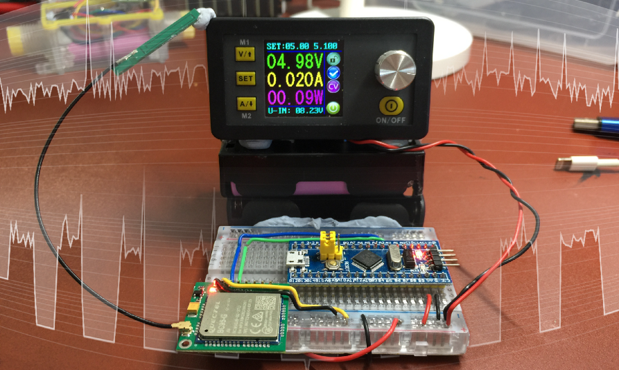
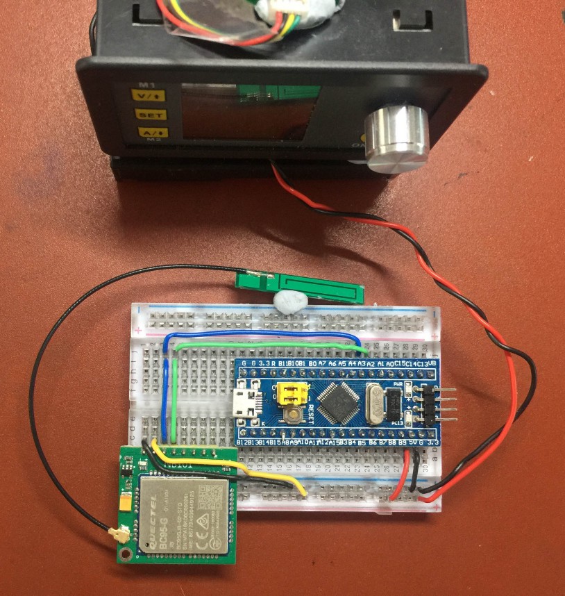
RuiDeng DPS 3005 Power Monitor measuring the power consumption of STM32 Blue Pill connected to Quectel BC95-G NB-IoT module
Low Power NB-IoT on STM32 Blue Pill with Apache Mynewt and Embedded Rust
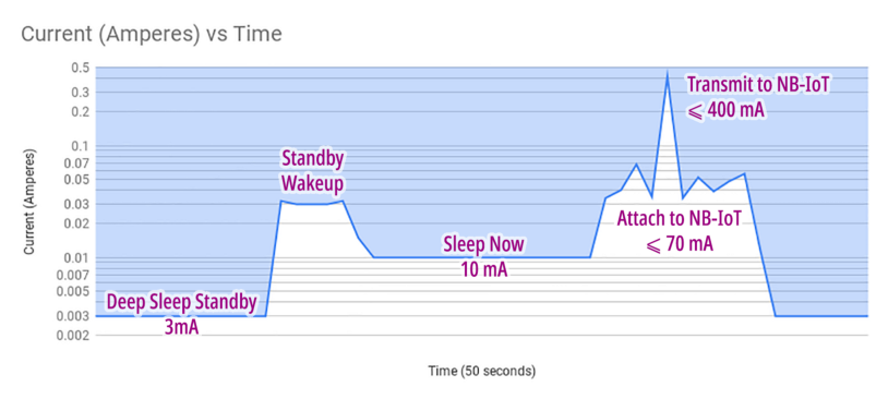
In this article we’ll learn to optimise the power consumption of the NB-IoT Sensor Application in the previous tutorial from this jagged power-hungry mess…
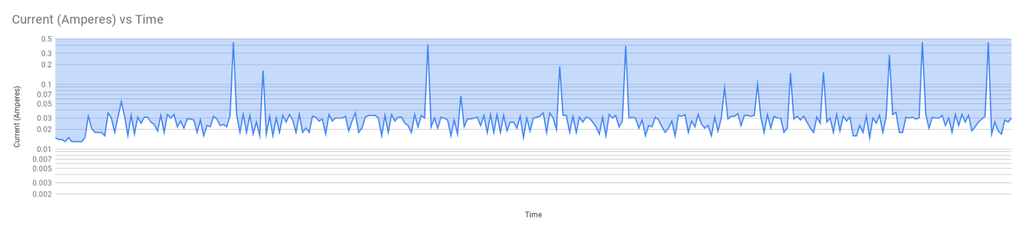
Power consumed by our IoT sensor device before optimisation. From https://docs.google.com/spreadsheets/d/1QptBX2wn_RC5-oaVPyxynbmKROO5ElfHJyNcqcX0YhA/edit?usp=sharing
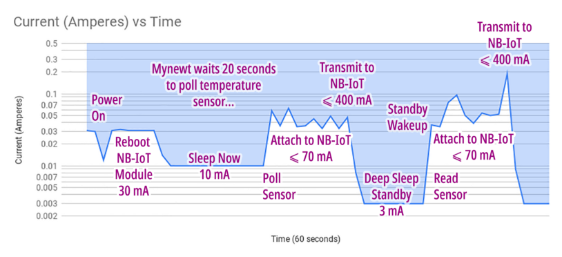
To these well-disciplined bars…
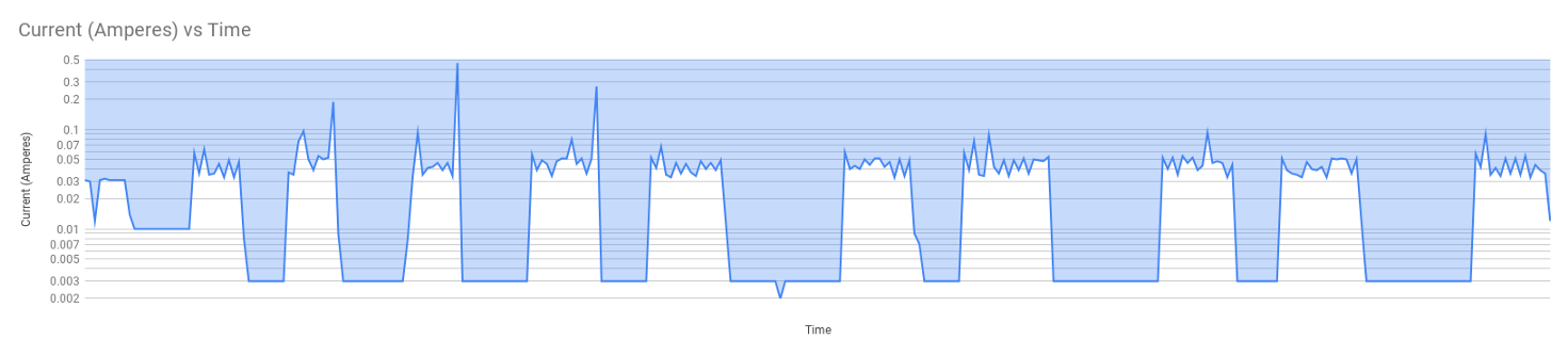
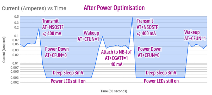
Power consumed by our IoT sensor device after optimisation. From https://docs.google.com/spreadsheets/d/1Rb6HXaHBaSAM3KW1aWOTyXjpJDiOCEWZAwpA-nufGKo/edit?usp=sharing
It’s a simple application (coded in Embedded Rust) that polls Blue Pill’s internal temperature sensor and transmits the sensor data to a server over NB-IoT.
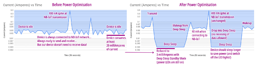
The power optimisation (recorded with a $25 RuiDeng DPS 3005 Power Monitor) becomes more apparent when we compare the charts side by side…

Power consumed by our IoT sensor device before and after optimisation. From https://docs.google.com/spreadsheets/d/1QptBX2wn_RC5-oaVPyxynbmKROO5ElfHJyNcqcX0YhA/edit?usp=sharing and https://docs.google.com/spreadsheets/d/1Rb6HXaHBaSAM3KW1aWOTyXjpJDiOCEWZAwpA-nufGKo/edit?usp=sharing
From the charts above we can see the secret to long battery life is this…
Stay in Deep Sleep for as long as possible!
Our sensor device doesn’t need to transmit sensor data every second. When it sleeps for a minute or more between transmissions, the battery life is dramatically increased.
However we need to be sure that our NB-IoT module won’t become totally disconnected from the network as Blue Pill sleeps. We have the solution for that.
Can we go below 3 milliAmperes?
Yes we can! Scrutinise the photo at the top of the article… Notice that TWO power LEDs are still lit: Power LED for Blue Pill and Power LED for the NB-IoT breakout board.
The two LEDs are always lit, even during Deep Sleep. If we desolder the two LEDs, the current consumed will surely drop way below 3 milliAmperes. My colleague Upton Lai has previously desoldered the Blue Pill Power LED and recorded 10 microAmperes of power consumption in Deep Sleep! (Without NB-IoT)
But for now we’ll keep the LEDs… My intent is to let you recreate this experiment easily using off-the-shelf hardware. So that you can follow me and discover for yourself the right way to conserve power.
There’s something odd about the Current values in the charts…
Yes the charts look different from High School Physics because I rendered the charts (in Google Sheets) using a Logarithmic Scale.
This makes the chart look more scenic and poetic like a rolling hill… instead of a desolate landscape with steep mountains and treacherous crevices. And I assure you that no values have been altered. (Just check the Google Sheets)
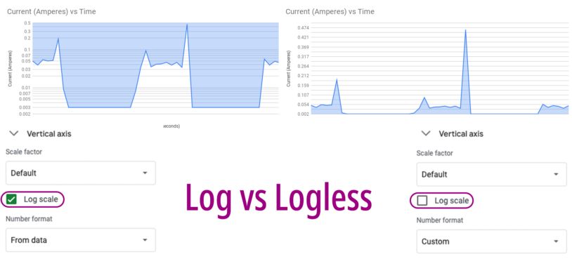
Logarithmic Scale vs Normal Scale. From https://docs.google.com/spreadsheets/d/1Rb6HXaHBaSAM3KW1aWOTyXjpJDiOCEWZAwpA-nufGKo/edit?usp=sharing
Quectel NB-IoT Power Consumption
It’s important to power down the
NB-IoT module when we have transmitted the data: AT+CFUN=0
According to the documentation for the above command in “Quectel BC95-G & BC68 AT Commands Manual”…
Deep sleep mode will be entered when the system is quiescent, but only if it has been enabled by the network.

Optimised NB-IoT Power Consumption. From https://docs.google.com/spreadsheets/d/1Rb6HXaHBaSAM3KW1aWOTyXjpJDiOCEWZAwpA-nufGKo/edit#gid=1194739783
Instead of keeping our device
always connected to NB-IoT, we would have to reattach to the NB-IoT network (AT+CGATT=1) every time we wake up. Attaching to the NB-IoT network
may take a few seconds, consuming 40 milliAmperes throughout.
(Mr Stefan de Lange kindly pointed out that we could attach to the NB-IoT network at power on instead of wakeup. We’ll explore that in a future article. Thanks Stefan!)
The actual NB-IoT transmission takes a split second, reaching peaks of about 400 milliAmperes.
Here’s the log from my optimised Blue Pill, chronicling the events after Deep Sleep Wakeup…
Blue Pill Log from https://github.com/lupyuen/stm32bluepill-mynewt-sensor/blob/low-power/logs/standalone-node-standby.log
Note that we used the NSOSTF command instead of NSOST to send a UDP packet with flags. In my previous article we
used…
AT+NSOST=1,104.199.85.211,5683,174,(data)…
Now we use…
AT+NSOSTF=1,104.199.85.211,5683,0x200,174,(data)…
The extra parameter 0x200 is the “Early Release” flag… It tells the NB-IoT network that
we are not expecting any response messages. So we can safely go to sleep and save power.
The “Early Release” flag was recommended by Mr Henk Vergonet at T-Mobile Netherlands
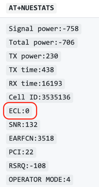
Here’s a valuable tip from Mr Stefan de Lange…
ECL is a key parameter to monitor. It determines the amount of repetitions the module will do. So instead of sending a message once the module might send the message 10, 20 or 30 times to make sure it arrives.
The ECL is displayed when we send
the AT+NUESTATS command.
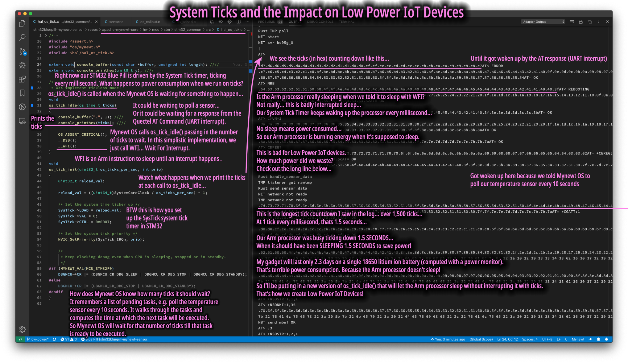
When Apache Mynewt Idles
Let’s dive deep into Mynewt and understand what happens when our Blue Pill is idle, waiting to poll the temperature sensor or waiting for an NB-IoT command to complete…
The Arm processor inside our Blue Pill has a built-in SysTick Timer. It’s used by Mynewt to perform multitasking. In the code above, Mynewt configures the SysTick Timer to generate an interrupt every millisecond.
When the millisecond interrupt is triggered, Mynewt checks whether it should continue running the current task, or switch to a higher-priority task. If there are no tasks ready to run (which will most likely be the case for our device), Mynewt still keeps checking every single millisecond. This is not good for battery life.
What happens when there are no
tasks ready to run? Mynewt calls os_task_idle(), passing the
number of ticks that it should stay idle. (1 tick = 1 millisecond)
Mynewt computes the idle time based on the list of pending tasks. So if the temperature sensor is supposed to be polled every 10 seconds, Mynewt knows that after polling the sensor, it should stay idle for roughly 10,000 ticks before resuming the polling task.
WFI in the code above is the Arm instruction “Wait For Interrupt”. It means that the Arm processor will go into a
power-saving quick nap (not Deep Sleep) until an interrupt occurs.
BUT… remember that our SysTick Interrupt occurs every millisecond… so our Blue Pill doesn’t sleep much!
Here’s proof of that… Watch what
happens when we add some debug output to os_task_idle()...
Proof that Blue Pill wakes up every millisecond
💎 “Heisenberg’s Uncertainty Principle” for Embedded Systems…
Don’t try at home what you see above! It’s NOT a good idea to display debug messages on the console when you’re deep inside the operating system… like in the Task Scheduling code above.
How did I do it? My
console_print()functions were specially designed to buffer output messages into RAM (usingmbufs). So no I/O is performed by the code above… Until the application flushes the console output.If this debug code used a normal console I/O call, it would interfere with the
os_task_idle()operation (it might get deadlocked). So when you insert debug code to observe what’s happening deep inside your microcontroller, you might actually affect the outcome.Hence some folks call this “Heisenberg’s Uncertainty Principle” (like in Quantum Mechanics)… Beware of Heisenberg! :-)
Going Tickless on Apache Mynewt with Real Time Clock
Here’s the problem: We would like to sleep longer and conserve power… But the SysTick Timer keeps waking us up every millisecond. Can we do without SysTick? Can we go… Tickless? Yes we can!
Blue Pill and other STM32 microcontrollers have an onboard Real Time Clock. Unlike a real wall clock, the Real Time Clock doesn’t tell you the time of the day. But it’s useful for two things…
1️⃣ Counting the ticks that have elapsed since we powered on our device. It keeps counting even in Deep Sleep!
2️⃣ Triggering an Alarm Interrupt at a time (in ticks) that we set
Remember that Mynewt calls os_task_idle(X) when it’s ready to sleep for X milliseconds. Why don’t we set the Real Time Clock Alarm to wake
us up in X milliseconds?
So in the optimised task
scheduler for Mynewt, we eliminate SysTick altogether, replaced by the Real Time Clock Alarm. os_task_idle() now calls power_sleep()…
From https://github.com/lupyuen/stm32bluepill-mynewt-sensor/blob/low-power/libs/low_power/src/low_power.c
What about WFI, the Wait For Interrupt instruction that we saw earlier? It
still works! Because the Real Time Clock triggers an interrupt (Alarm Interrupt) when the time is up.
Here’s how we call WFI for a quick nap (Sleep Now Mode)…
From https://github.com/lupyuen/stm32bluepill-mynewt-sensor/blob/low-power/libs/low_power/src/low_power.c
The power_sleep() function calls target_enter_sleep_mode() and WFI for a quick nap. When we have finished transmitting our sensor
data over NB-IoT, we could actually take a longer nap… this is the Deep Sleep
Standby Mode we saw earlier… the one that consumes only 3 milliAmperes! (With the power
LEDs still lit) We’ll cover Deep Sleep Standby Mode in a while.
Zephyr RTOS has a good explanation of Tickless Task Scheduling here
Power Saving Modes on Blue Pill
There are three power saving modes on Blue Pill…
1️⃣ Sleep
Now Mode (10 milliAmperes): This is the WFI (Wait For
Interrupt) instruction that’s implemented in the Arm processor. It puts Blue Pill into a light nap
that still consumes substantial power. That’s because the Blue Pill peripherals (like the UART port)
are still powered on.
2️⃣ Deep Sleep Stop Mode: Similar to Sleep Now Mode, except that the peripherals (like UART) are powered down. Consumes less power than Sleep Now Mode but more power than Deep Sleep Standby Mode. On wakeup, Blue Pill resumes execution with the peripherals powered down. RAM is preserved.
3️⃣ Deep Sleep Standby Mode (3 milliAmperes, with power LEDs still lit): The ultimate low power mode. All peripherals powered down (same as Deep Sleep Stop Mode). BUT on wakeup, Blue Pill restarts as though it was just powered on. Everything in RAM is lost.
Sleep Now Mode vs Deep Sleep Standby Mode. From https://docs.google.com/spreadsheets/d/1ygUzKYWTo-BSSvKzL3J6ub3o4-7sVrjMUyvGLdAsHJ0/edit?usp=sharing
This may sound odd… But Deep Sleep Standby Mode (the ultimate power saver) is easier to code than Deep Sleep Stop Mode.
With Stop Mode we need to power on the peripherals ourselves when waking up… And it gets complicated. With Standby Mode, we just pretend that our Blue Pill has just powered on… Except that we can check a flag to distinguish whether it’s a Power On or a Standby Wakeup.
Here’s how we check the flag…
Embedded Rust Application For Low Power
Remember from our previous tutorial that the IoT Sensor Application was developed in Rust. Is Rust really suitable for Low Power Devices? Does Rust make our device less power-efficient?
I’m happy to report that Rust is just as power-efficient as C! That’s because Rust is compiled into optimised Arm machine code, so there’s no extra execution overhead when our application is written in Rust.
The Rust application logic was tweaked slightly to make it more power-efficient…
From https://github.com/lupyuen/stm32bluepill-mynewt-sensor/blob/low-power/rust/app/src/app_sensor.rs
The top half of the function
start_sensor_listener() is exactly the same as before. When our
device is powered up, we instruct Mynewt to poll the temperature sensor every 20 seconds. Mynewt
passes the sensor data to our function handle_sensor_data() for
transmitting to the server.
From https://github.com/lupyuen/stm32bluepill-mynewt-sensor/blob/low-power/rust/app/src/app_sensor.rs
The lower half of start_sensor_listener() introduces a minor twist… When our device
wakes up from Deep Sleep Standby Mode, we read the temperature sensor directly, without polling. And
we transmit the sensor data the same way, via handle_sensor_data().
This keeps our device fully occupied during the precious few seconds that our device is awake, until it falls into Deep Sleep.
The Sensor Network Library (written in C) has been optimised for low power operation as well. During wakeup, the function attaches to the NB-IoT network and doesn’t return until it completes. (Previously we started a background task to attach to the NB-IoT network so that we could run other tasks.)
This chart illustrates the power consumed when our Blue Pill polls the onboard temperature sensor vs reading the sensor directly.
Polling vs Reading the temperature sensor. From https://docs.google.com/spreadsheets/d/1Rb6HXaHBaSAM3KW1aWOTyXjpJDiOCEWZAwpA-nufGKo/edit#gid=1194739783
The code changes are really minor. Mynewt’s Sensor Framework has done an excellent job in managing the access to sensors in a consistent, reusable way, even for Low Power. And Rust makes the code look much cleaner and simpler than C.
Measure Power Consumption with RuiDeng DPS 3005 Power Monitor
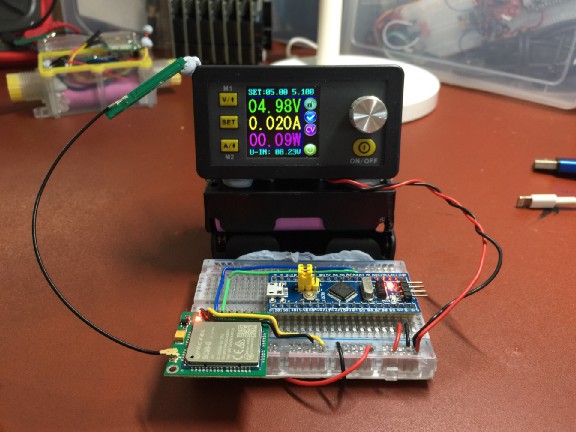
RuiDeng DPS 3005 Power Monitor measuring the power consumption of STM32 Blue Pill connected to Quectel BC95-G NB-IoT module
Now let’s run our IoT Sensor Device and measure the power consumption with RuiDeng DPS 3005 Power Monitor!
Follow the instructions here to connect Blue Pill to the NB-IoT module and ST-Link.
Let’s look at inputs and outputs for the Power Monitor…
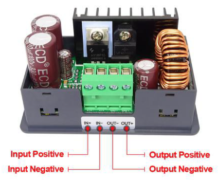
Inputs and Outputs for RuiDeng DPS 3005 Power Monitor
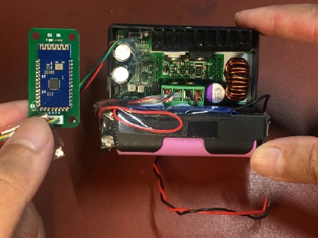
Inputs at
Left Side (IN+, IN-): Connect to the DC power supply. I used two 18650 lithium ion 3.7 Volt
batteries connected in series. Total 7.2 Volts, sufficient for providing 5 Volts to our Blue Pill and
NB-IoT module.
Outputs at
Right Side (OUT-, OUT+): Connect to the Blue Pill and NB-IoT module. This will be the 5-Volt power
source for our Blue Pill and NB-IoT module.
Here’s how I powered my Power Monitor…
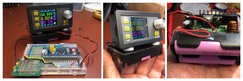
RuiDeng DPS 3005 Power Monitor powered by two 18650 lithium ion 3.7 Volt batteries

When Flashing Firmware…
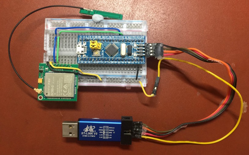
Blue Pill and NB-IoT Module connected to ST-Link
When flashing the firmware to Blue Pill, connect ST-Link to Blue Pill and the NB-IoT module as shown.
Note that the NB-IoT module is powered by the 5V pin from ST-Link.
Blue Pill’s 5V pin should be disconnected.
When Monitoring Power Consumption…
Blue Pill and NB-IoT Module connected to RuiDeng DPS 3005 Power Monitor
When monitoring the power consumption, disconnect ST-Link.
Connect Blue Pill’s 5V pin to the Power Meter.
The NB-IoT module should be powered by the Power Meter as well.
Bluetooth module for DPS 3005 Power Monitor
Make sure your DPS 3005 Power Monitor is bundled with a Bluetooth module.
The module connects the Power Monitor to your Windows computer wirelessly for recording data power consumption data (at 1 sample per second). Sadly I couldn’t connect from macOS.
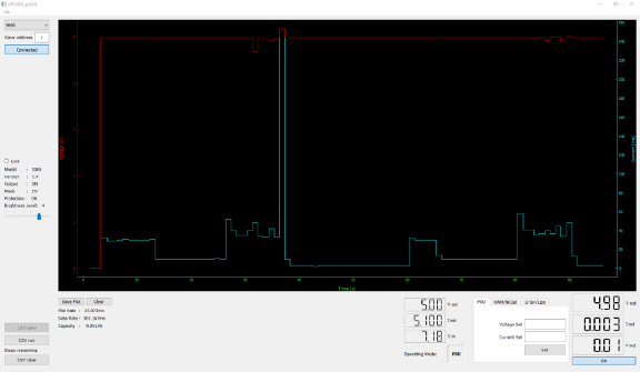
RuiDeng’s software for DPS 3005
did not allow recording of data, so I used the open-source DPS5005_pyGUI
data logger.
DPS5005_pyGUI data logger: https://github.com/lambcutlet/DPS5005_pyGUI
The low power version of Apache Mynewt and the updated Embedded Rust application may be installed according to these instructions.
Is 1 sample per second sufficient for understanding the power consumption?
Honestly, no. There are peaks in our power consumption during NB-IoT transmission. The peaks seem to reach 400 milliAmperes… But because the sampling rate is so low, the peaks could possibly be much higher than that.
Peaks in NB-IoT Power Consumption. From https://docs.google.com/spreadsheets/d/1Rb6HXaHBaSAM3KW1aWOTyXjpJDiOCEWZAwpA-nufGKo/edit#gid=1194739783
Nonetheless, we now have a $25 setup that lets us quickly tweak our firmware and check whether the tweaks actually improve power consumption. So the RuiDeng Power Monitor is an affordable way to guide us towards the right direction to reduce power consumption. When you have finalised the firmware, remember to use the proper equipment to measure the real power consumption!
The Results
After optimising the power consumption, how much longer did the battery last? A whopping… 26% increase in battery life!
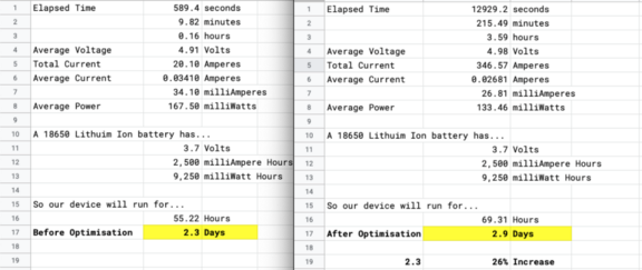
Computed battery life for our IoT sensor device. From https://docs.google.com/spreadsheets/d/1QptBX2wn_RC5-oaVPyxynbmKROO5ElfHJyNcqcX0YhA/edit#gid=1065153023 and https://docs.google.com/spreadsheets/d/1Rb6HXaHBaSAM3KW1aWOTyXjpJDiOCEWZAwpA-nufGKo/edit#gid=1872735739
But it’s a good start! Remember that the power LEDs are still lit. And we have achieved flat lines of power usage during Deep Sleep.
Power consumed by our IoT sensor device before and after optimisation. From https://docs.google.com/spreadsheets/d/1QptBX2wn_RC5-oaVPyxynbmKROO5ElfHJyNcqcX0YhA/edit?usp=sharing and https://docs.google.com/spreadsheets/d/1Rb6HXaHBaSAM3KW1aWOTyXjpJDiOCEWZAwpA-nufGKo/edit?usp=sharing
Right now our Blue Pill wakes up every 1 minute or so… If we could extend the Deep Sleep to 10 minutes or longer, we should get much lower overall power consumption.
Unfortunately I couldn’t get Blue Pill to sleep beyond 1 minute… Something is still waking it up. Another timer? Or NB-IoT?
I invite you to reproduce the same setup with the steps I have described… And help me solve the mystery! (Or work around it… See the “Backup Registers” section below)
But I hope you now have a deeper appreciation of all the components that make an IoT Sensor truly Low Power… the Network (NB-IoT), the Microcontroller (STM32) and the Operating System (Mynewt)!
Many thanks to StarHub for sponsoring the NB-IoT SIM that I used for this article!

Final data collection with RuiDeng DPS 3005 Power Monitor connected to STM32 Blue Pill and Quectel BC95-G NB-IoT module. The Bluetooth module for the Power Monitor is in the centre (green board with red LED).
💎 Advanced Topic: Main and Backup Power
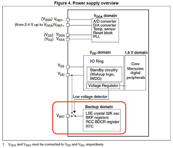
From “RM0008 Reference manual for STM32F103xx”: https://www.st.com/content/ccc/resource/technical/document/reference_manual/59/b9/ba/7f/11/af/43/d5/CD00171190.pdf/files/CD00171190.pdf/jcr:content/translations/en.CD00171190.pdf
Let’s study the power input for
STM32F103C8T6, the STM32 microcontroller at the heart of Blue Pill.
Most parts of STM32F103C8T6 are powered by the Main Power (VDD in the above diagram).
STM32F103C8T6 has a Backup Domain (highlighted in red) that may be
powered by Main Power VDD or Backup
Power VBAT. The Backup Domain contains the minimum
components essential for Deep Sleep, such as the Real Time Clock.
This means that it’s possible to
sustain Blue Pill in Deep Sleep just by supplying a bit of Backup Power to the VBAT pin, while the rest of Blue Pill (running on Main Power) is
powered down.
Everything in the Backup Domain continues to operate as long as Backup Power is available. What’s inside the Backup Domain?
1️⃣ Low Speed External (LSE) Oscillator: This generates the ticks that’s needed by the Real Time Clock to track time accurately during Deep Sleep
2️⃣ Backup Registers (BKP): These are ten 16-bit registers that we may use to store 20 bytes of data. The contents of the registers will be preserved across restarts and wakeups, as long as Backup Power is available. We’ll see later how Backup Registers may be used.
3️⃣ Backup Domain Control Register (BDCR): This register is used to configure the LSE Oscillator and Real Time Clock.
4️⃣ Real Time Clock (RTC): This is needed to count the ticks produced by the LSE Oscillator and track the elapsed time accurately. It also wakes up the microcontroller at the preset alarm time.
💎 Advanced Topic: Configure the Real Time Clock
This section explains how we
configured the Real Time Clock on Blue Pill. The alarm_setup()
code looks tricky so we’ll study this step by step.
The alarm_setup() function is called at startup and wakeup by __wrap_os_tick_init(),
which is the intercepted version of os_tick_init() that we’ll
see in the section “Advanced Topic: Patch Mynewt OS Functions” below.
From https://github.com/lupyuen/stm32bluepill-mynewt-sensor/blob/low-power/libs/low_power/src/alarm.c
Blue Pill has three Oscillator Clocks: HSE, LSE and LSI. These are primitive clocks, good for producing ticks only. We may select one of these Oscillator Clocks to drive the Real Time Clock and trigger the Deep Sleep wakeup alarm.
1️⃣ High Speed External (HSE) is the fastest clock (8 MHz crystal oscillator)… But also needs the most power. HSE uses only Main Power, doesn’t work on Backup Power. So when we sleep and switch to Backup Power, it stops. Not suitable for setting the Deep Sleep alarm.
2️⃣ Low Speed Internal (LSI) is a slower clock (~40 kHz RC oscillator) but it also runs on Main Power, not Backup Power. So it’s not suitable for setting the Deep Sleep alarm either.
3️⃣ Low Speed External (LSE) (32.768 kHz crystal oscillator) is the best choice because it works on Backup Power (assuming that our Blue Pill has a Backup Power source when it goes into Deep Sleep)
What’s “Prescaling”? Something you do on a fish? No, prescaling lets us run the Real Time Clock as a fraction of the HSE / LSE / LSI clock speeds. So when we prescale LSE by 32, we run the Real Time Clock at 1 tick per millisecond. (LSE ticks natively at 32.768 kHz, or 32,768 ticks per second)
From https://github.com/lupyuen/stm32bluepill-mynewt-sensor/blob/low-power/libs/low_power/src/alarm.c
Real Time Clock may be used in 3 ways to trigger interrupts…
1️⃣ After a
preset number of ticks (RTC_SEC). So that the STM32
microcontroller’s Real Time Clock may be used like the Arm processor’s SysTick Timer.
2️⃣ At a
preset alarm time (RTC_ALR). We’re using this to wake
up from Deep Sleep.
3️⃣ Upon
overflow (RTC_OW). The Real Time Clock is a 32-bit
counter that counts the number of elapsed ticks from 0 to 4,294,967,295. When the counter overflows,
the Real Time Clock triggers this interrupt so that the operating system can do the necessary time
adjustments.
We’ll be using only the Alarm
Interrupt RTC_ALR. When the alarm goes off, the Arm processor
will call our function rtc_alarm_isr()
From https://github.com/lupyuen/stm32bluepill-mynewt-sensor/blob/low-power/libs/low_power/src/alarm.c
At power on we switch on the Real
Time Clock and set the counter value to 0 (rtc_set_counter_val).
This is the counter we’ll be using to track the elapsed time (as millisecond ticks) in our
application.
From https://github.com/lupyuen/stm32bluepill-mynewt-sensor/blob/low-power/libs/low_power/src/alarm.c
During wakeup from Deep Sleep we don’t reset the Real Time Clock counter. That way we can track the elapsed time as Blue Pill sleeps. Remember that the Real Time Clock keeps counting the ticks during Deep Sleep (powered by Backup Power).
From https://github.com/lupyuen/stm32bluepill-mynewt-sensor/blob/low-power/libs/low_power/src/alarm.c
For Deep Sleep Stop Mode: The
External Interrupt (EXTI) must be configured so that the Alarm Interrupt will wake us up (exti_set_trigger). This is not necessary for Deep Sleep Standby
Mode.
From https://github.com/lupyuen/stm32bluepill-mynewt-sensor/blob/low-power/libs/low_power/src/alarm.c
Once we enable the Alarm
Interrupt via rtc_interrupt_enable(RTC_ALR), the alarm becomes
operational. We will call rtc_set_alarm_time() to set the alarm
time (in ticks). When the alarm goes off, our function rtc_alarm_isr() will be called.
Here’s how we set the alarm time before entering Deep Sleep…
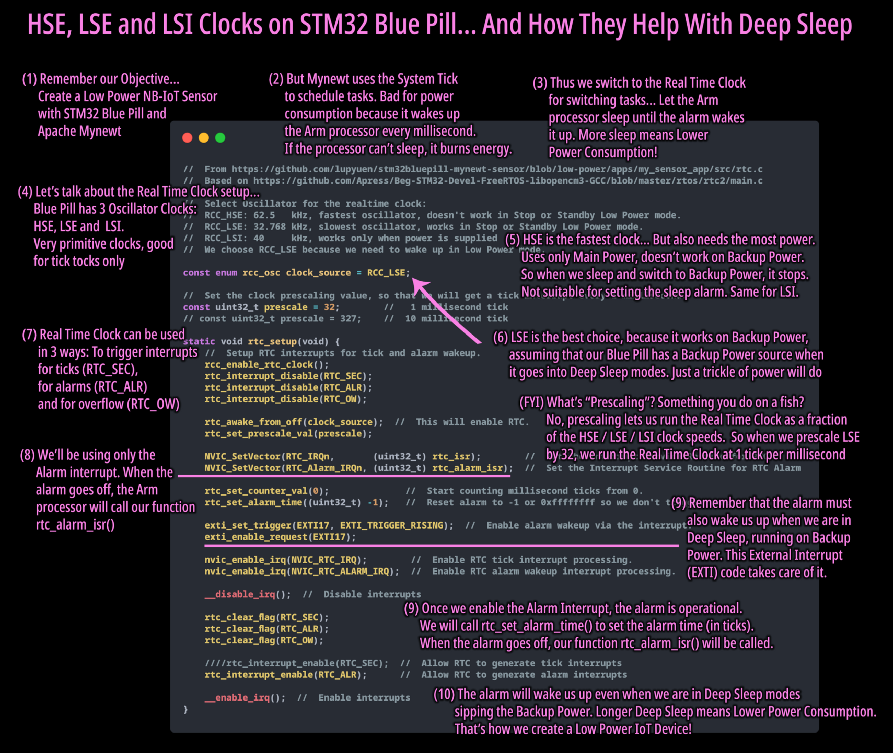
HSE, LSE and LSI clocks on STM32 Blue Pill
💎 Advanced Topic: Backup Registers
Here’s the problem: Blue Pill wakes up from Deep Sleep Standby Mode with amnesia… It doesn’t know what it was doing before it fell into Deep Sleep, since the RAM has been erased. How can we make Blue Pill memorise some state information so that it can resume working after waking up? Without writing to Flash ROM?
Solution: Use the STM32 Backup Registers. Blue Pill’s Backup Registers are ten 16-bit registers that we may use to store 20 bytes of data. The contents of the registers will be preserved across restarts and wakeups, as long as there is Backup Power (or Main Power) supplied to Blue Pill. It works just the Real Time Clock!
This code was used in my Bootloader (from an earlier article) to remember whether Blue Pill is supposed to restart in Bootloader Mode or Application Mode. Check out the article: “STM32 Blue Pill — Bootloading the WebUSB Bootloader”
💎 Advanced Topic: Patch Mynewt OS Functions
The low power functions were
implemented in a custom library libs/low_power.
How did we patch the Mynewt OS functions like os_task_idle()
with our custom library? By using the Linker Wrap directive in our library…
When the GNU Linker collates the
compiled object files (*.o) to create the firmware image, it
will look for all calls to os_tick_idle() and rename them as
calls to __wrap_os_tick_idle().
Note that GNU Linker will NOT
rename the original os_tick_idle() function defined in Mynewt.
Which means that we may implement the __wrap_os_tick_idle()
function ourselves and the callers will happily pretend that it’s really os_tick_idle(). That’s how we intercept system functions in Mynewt…
It’s a nasty way to alter the behaviour of Mynewt (and I don’t condone it). But for exploratory and educational purposes, it’s probably OK.
Note that the firmware size is
close to 60 KB. Adding the 4 KB Stub Bootloader we get total 64 KB of Flash ROM used. This is very
close to Blue Pill’s 64 KB ROM capacity. When you’re not debugging, uncomment the -Os option in apps/my_sensor_app/pkg.yml
#  C compiler flags
pkg.cflags:
    - -DFLOAT_SUPPORT  #  For encoding floats in CoAP messages
#   - -Os              #  Optimise for smallest size
Also the random number generator
has been disabled to reduce code size, hence the Device ID is always 0000… To enable it, change HMAC_PRNG to 1 in targets/bluepill_my_sensor/syscfg.yml
HMAC_PRNG: 0 # Disable HMAC PRNG pseudorandom number generator