📝 28 Dec 2022
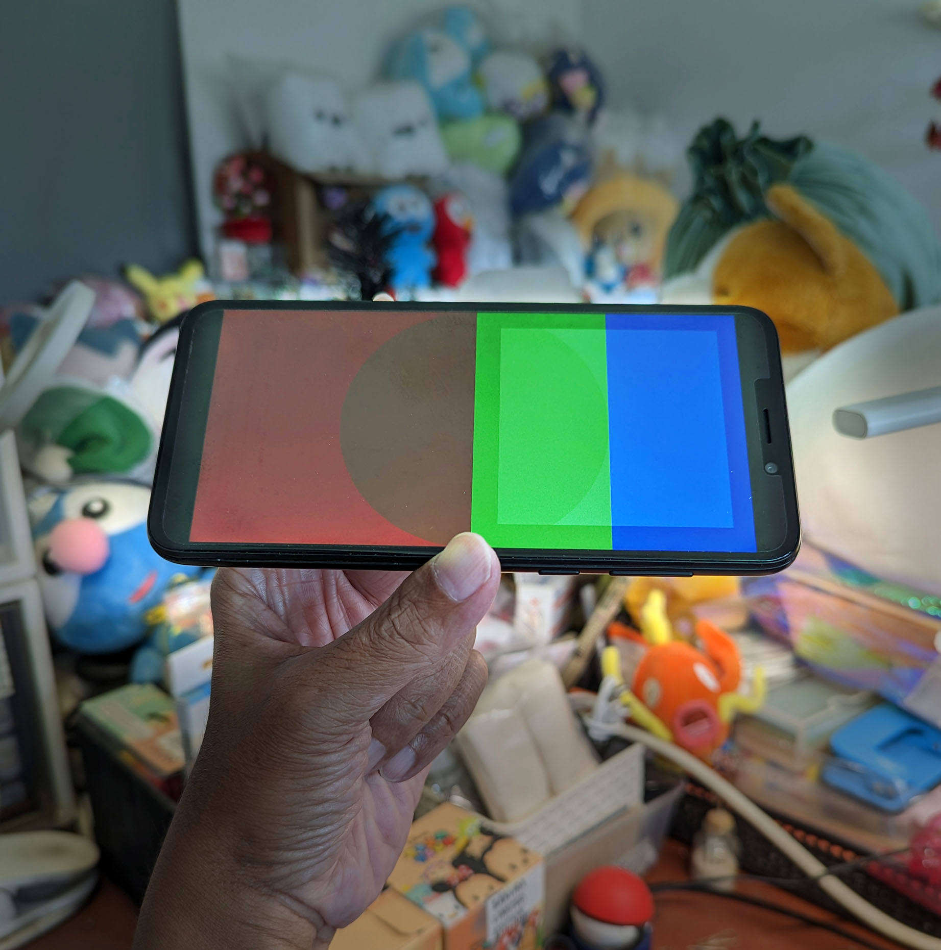
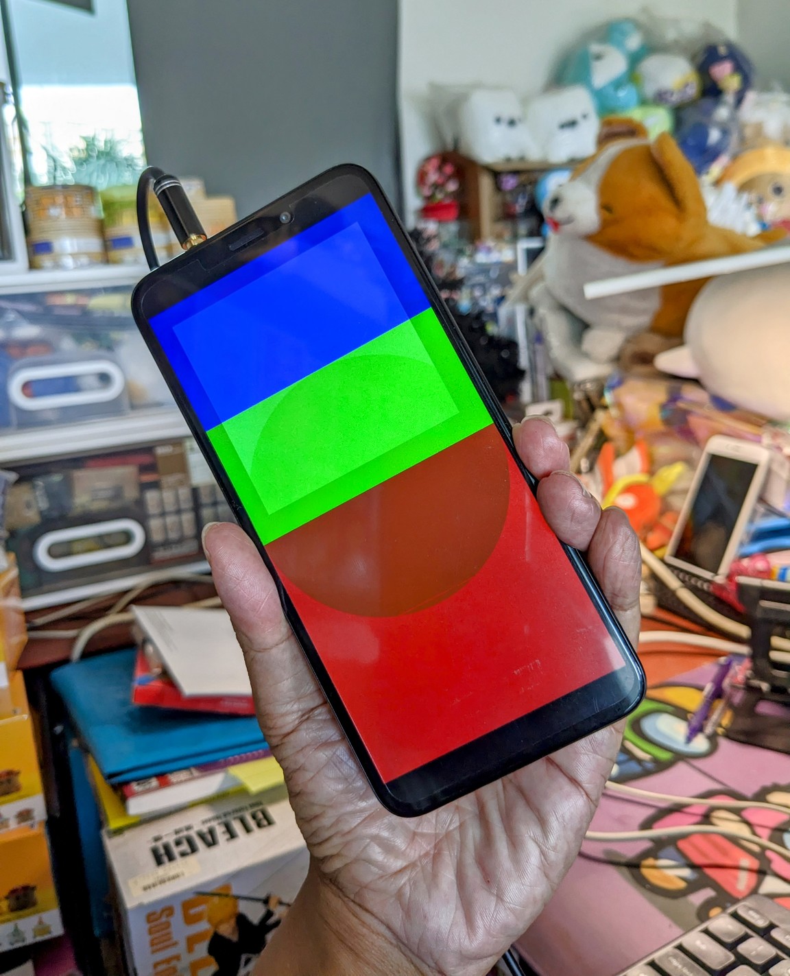
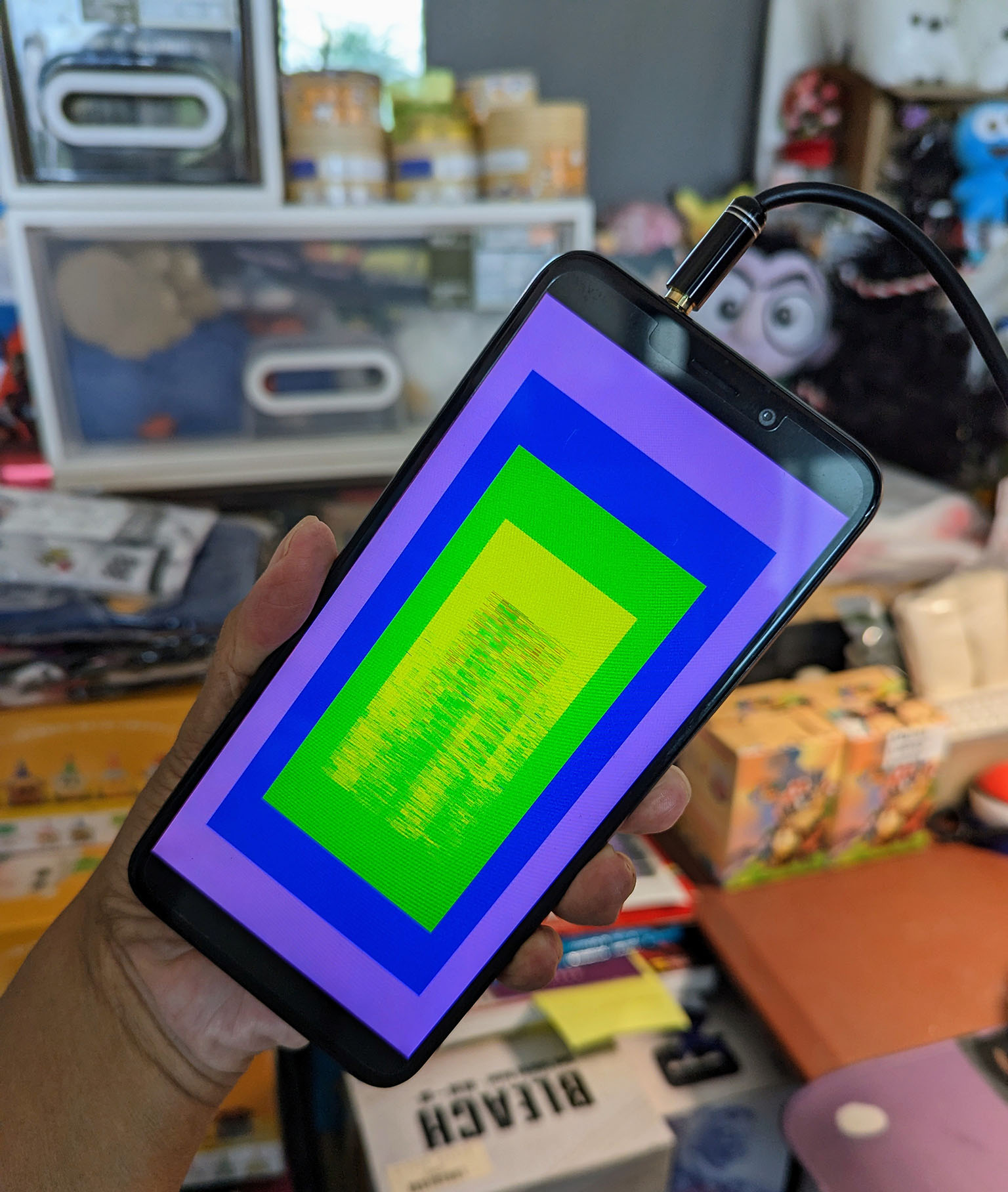
Apache NuttX RTOS now boots on Pine64 PinePhone and renders a Test Pattern! (Pic above)
Let’s find out what’s inside our NuttX Kernel Driver for PinePhone’s LCD Panel…
LCD Display on PinePhone Schematic (Page 2)
The LCD Panel inside PinePhone is Xingbangda XBD599 (兴邦达) with…
(Includes a Capacitive Touch Panel, but we won’t touch it today heh)
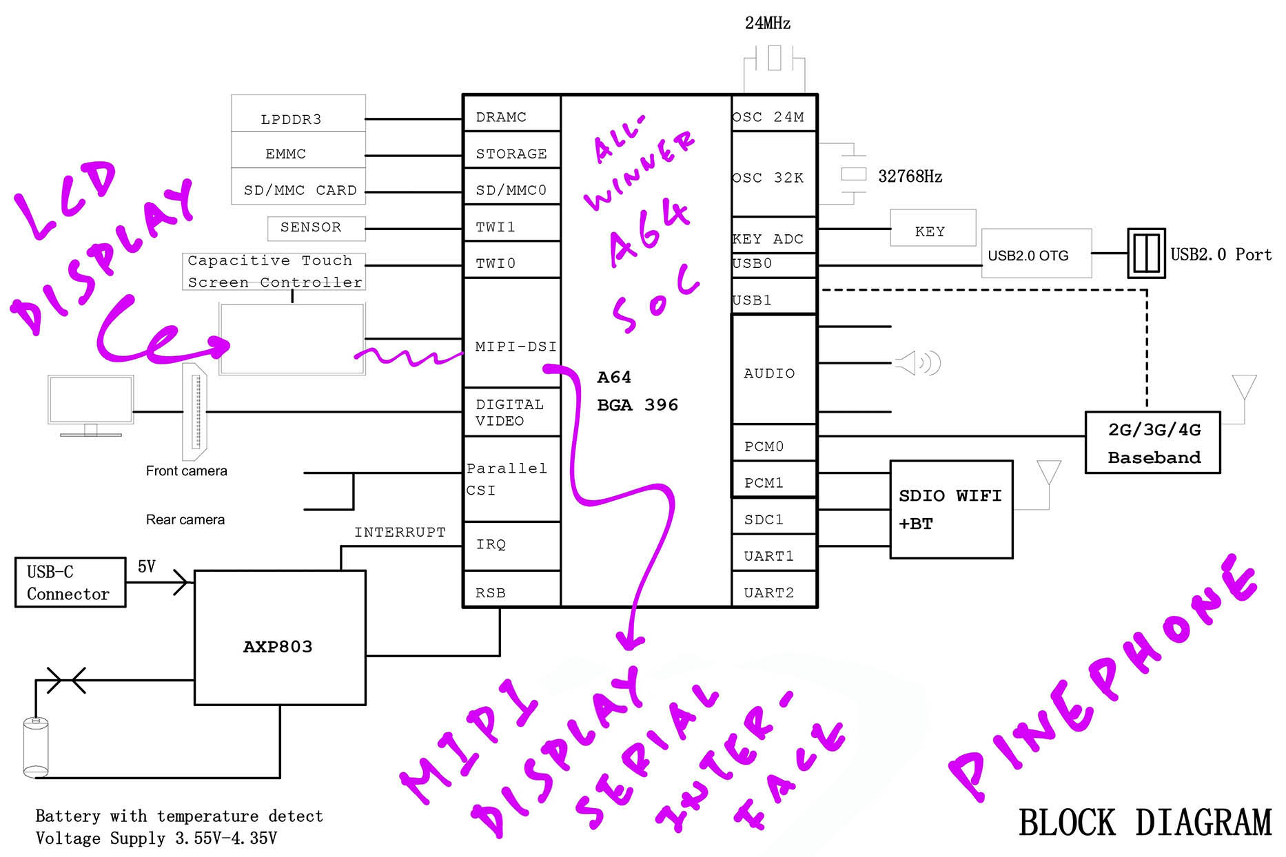
The Xingbangda XBD599 LCD Panel is connected to PinePhone’s Allwinner A64 SoC over a MIPI Display Serial Interface (DSI). (Pic above)
Why is there an ST7703 LCD Controller inside the LCD Panel?
Talking over MIPI DSI can get complicated… It runs on packets of data with CRCs and Checksums, over multiple data lanes.
Later we’ll see that ST7703 LCD Controller handles…
MIPI DSI Initialisation Commands
(At startup)
Rendering of Pixels over MIPI DSI
(After startup)
Let’s start with something simpler without ST7703…
Turn on the LCD Panel Backlight
(With PIO and PWM)
Reset the LCD Panel
(With PIO)
Power on the LCD Panel
(With PMIC)
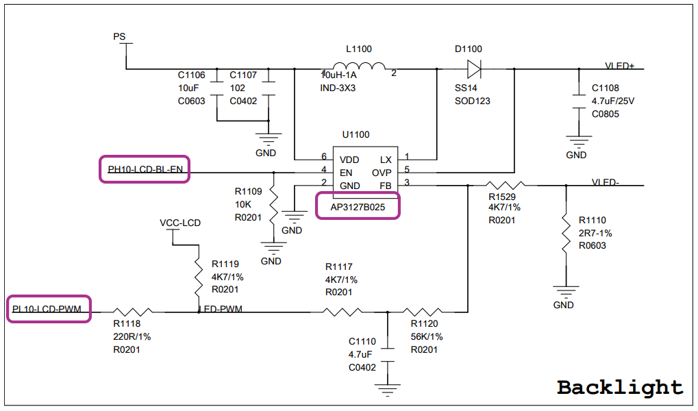
Backlight on PinePhone Schematic (Page 11)
First thing we do when booting PinePhone is to turn on the LCD Panel Backlight… Otherwise the LCD Display stays dark!
The PinePhone Schematic (Page 11) says that the LCD Panel Backlight is controlled by two pins (pic above)…
PL10 for Pulse-Width Modulation (PWM)
PH10 for PIO (Similar to GPIO)
The two pins are connected to Diodes AP3127, which is a PWM Controller. (Pic above)
This is how we turn on the backlight in our NuttX LCD Driver: pinephone_lcd.c
// Turn on the LCD Backlight
int pinephone_lcd_backlight_enable(
  uint32_t percent  // Brightness percentage, typically 90
) {
  // Configure PL10 for PWM
  a64_pio_config(LCD_PWM);  // LCD_PWM is PL10
We begin by configuring PL10 for PWM.
(a64_pio_config comes from our NuttX PIO Driver)
Next we disable PWM through the R_PWM Port on Allwinner A64…
  // R_PWM Control Register (Undocumented)
  // Assume same as PWM Control Register (A64 Page 194)
  // Set SCLK_CH0_GATING (Bit 6) to 0 (Mask)
  modreg32(  // Modify a Register...
    0,                // Set these bits
    SCLK_CH0_GATING,  // Mask these bits
    R_PWM_CTRL_REG    // Register Address
);(R_PWM is implemented in the Allwinner A100 Coprocessor)
The R_PWM Port isn’t documented in the Allwinner A64 User Manual.
But thanks to Reverse-Engineering, we figured out how it works: pinephone_lcd.c
  // R_PWM Control Register (Undocumented)
  // Assume same as PWM Control Register (A64 Page 194)
  #define R_PWM_CTRL_REG            (A64_RPWM_ADDR + 0)
  #define PWM_CH0_PRESCAL(n)        ((n) << 0)
  #define PWM_CH0_EN                (1 << 4)
  #define SCLK_CH0_GATING           (1 << 6)

  // R_PWM Channel 0 Period Register (Undocumented)
  // Assume same as PWM Channel 0 Period Register (A64 Page 195)
  #define R_PWM_CH0_PERIOD          (A64_RPWM_ADDR + 4)
  #define PWM_CH0_ENTIRE_ACT_CYS(n) ((n) << 0)
  #define PWM_CH0_ENTIRE_CYS(n)     ((n) << 16)
Then we set the PWM Period and Duty Cycle: pinephone_lcd.c
  // R_PWM Channel 0 Period Register (Undocumented)
  // Assume same as PWM Channel 0 Period Register (A64 Page 195)
  // Set PWM_CH0_ENTIRE_CYS (Bits 16 to 31) to PWM Period
  // Set PWM_CH0_ENTIRE_ACT_CYS (Bits 0 to 15) to PWM Period * Percent / 100
  // `BACKLIGHT_PWM_PERIOD` is 1,199 PWM cycles
  // `percent` (brightness percent) is typically 90
  uint32_t period =
    PWM_CH0_ENTIRE_CYS(BACKLIGHT_PWM_PERIOD) |
    PWM_CH0_ENTIRE_ACT_CYS(BACKLIGHT_PWM_PERIOD * percent / 100);
  putreg32(           // Write to Register...
    period,           // Register Value
    R_PWM_CH0_PERIOD  // Register Address
  );
Finally we enable PWM…
  // R_PWM Control Register (Undocumented)
  // Assume same as PWM Control Register (A64 Page 194)
  // Set SCLK_CH0_GATING (Bit 6) to 1 (Pass)
  // Set PWM_CH0_EN (Bit 4) to 1 (Enable)
  // Set PWM_CH0_PRESCAL (Bits 0 to 3) to 0b1111 (Prescaler 1)
  uint32_t ctrl = SCLK_CH0_GATING |
    PWM_CH0_EN |
    PWM_CH0_PRESCAL(0b1111);
  putreg32(         // Write to Register...
    ctrl,           // Register Value
    R_PWM_CTRL_REG  // Register Address
  );
One last thing: We configure PH10 for Output and set it to High…
  // Configure PH10 for Output
  a64_pio_config(LCD_BL_EN);  // LCD_BL_EN is PH10

  // Set PH10 to High
  a64_pio_write(LCD_BL_EN, true);
  return OK;
}(a64_pio_write comes from our NuttX PIO Driver)
This enables the AP3127 PWM Controller. And switches on the LCD Backlight! (Pic above)
Now that the Backlight is on, let’s reset the LCD Panel and prepare for action…
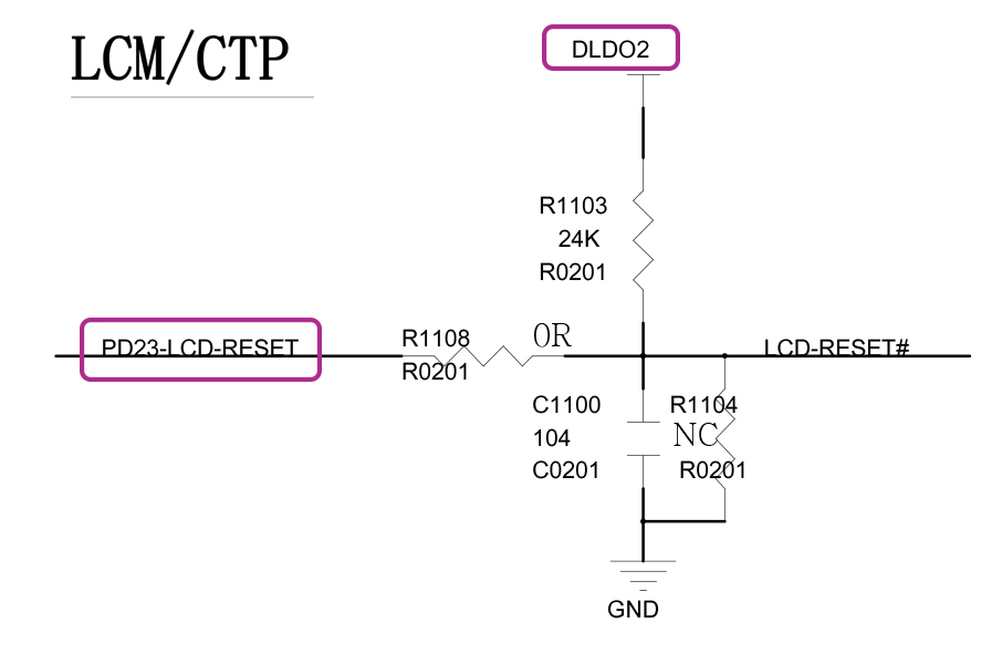
LCD Panel Reset (PD23) on PinePhone Schematic (Page 11)
At startup, we need to toggle the LCD Reset from Low to High in this specific sequence…
Reset LCD Panel to Low
Power on the LCD Panel’s MIPI Display Serial Interface (DSI)
(Via the Power Management Integrated Circuit)
Wait 15 milliseconds
Enable MIPI DSI on Allwinner A64 SoC
Enable MIPI D-PHY on Allwinner A64 SoC
Reset LCD Panel to High
Followed by more MIPI DSI and Display Engine operations.
How will we toggle LCD Reset?
The PinePhone Schematic (Page 11) says that LCD Reset is controlled on PD23. (Pic above)
(DLDO2 is powered by the PMIC)
Let’s do it: pinephone_lcd.c
// Reset the LCD Panel
int pinephone_lcd_panel_reset(
  bool val  // Set Reset to High or Low
) {
  // Reset LCD Panel at PD23 (Active Low)
  // Configure PD23 for Output
  a64_pio_config(LCD_RESET);  // LCD_RESET is PD23

  // Set PD23 to High or Low
  a64_pio_write(LCD_RESET, val);
  return OK;
}
The code above configures PD23 for Output, and sets PD23 to High or Low.
(a64_pio_config comes from our NuttX PIO Driver)
And that’s how we reset the LCD Panel! Now we power on the LCD Panel…
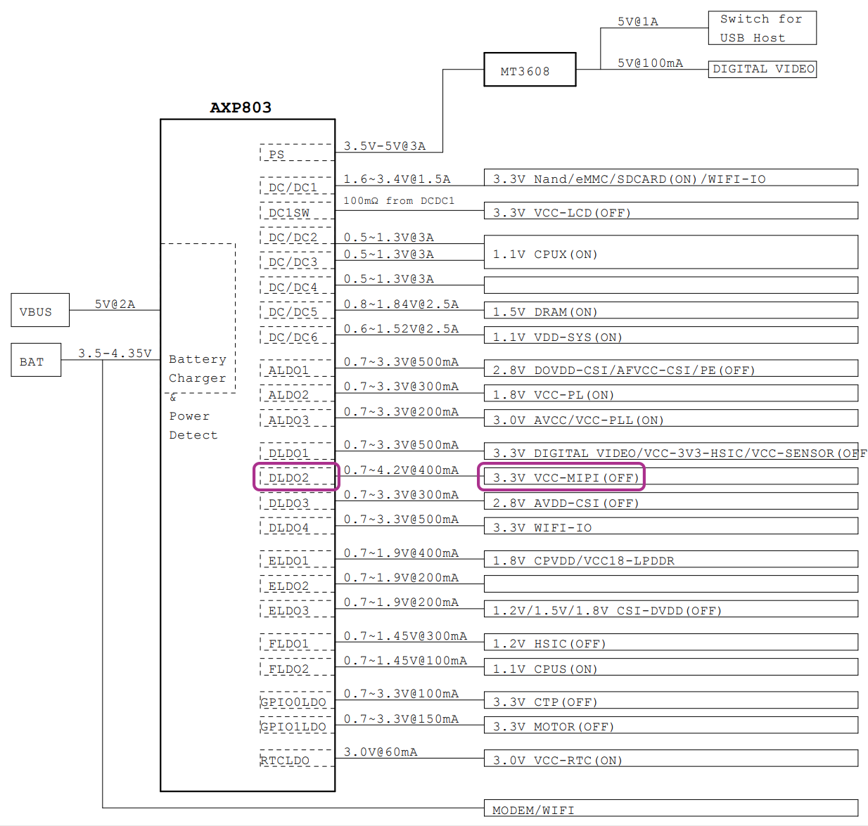
AXP803 PMIC on PinePhone Schematic (Page 3)
How do we power on the LCD Panel?
The LCD Panel won’t respond to our MIPI DSI Commands until we power it on.
The PinePhone Schematic (Page 3) says that the MIPI DSI Port of the LCD Panel (DLDO2 / VCC-MIPI) is powered by…
X-Powers AXP803 Power Management Integrated Circuit (PMIC)
(Pics above and below)
This is how we talk to the AXP803 PMIC: pinephone_pmic.c
// Initialise the Power Mgmt IC
int pinephone_pmic_init(void) {
  // Set DLDO1 Voltage to 3.3V.
  // DLDO1 powers the Front Camera / USB HSIC / I2C Sensors.

  // DLDO1 Voltage Control (AXP803 Page 52)
  // Set Voltage (Bits 0 to 4) to 26 (2.6V + 0.7V = 3.3V)
  pmic_write(               // Write to PMIC Register...
    DLDO1_VOLTAGE_CONTROL,  // PMIC Register
    DLDO1_VOLTAGE(26)       // PMIC Value
  );

  // Power on DLDO1:
  // Output Power On-Off Control 2 (AXP803 Page 51)
  // Set DLDO1 On-Off Control (Bit 3) to 1 (Power On)
  pmic_clrsetbits(  // Clear and set bits in PMIC Register...
    OUTPUT_POWER_ON_OFF_CONTROL2,  // Set these bits
    0,                             // Clear these bits
    DLDO1_ON_OFF_CONTROL           // PMIC Register
  );
DLDO1 Power Output on the PMIC powers the Front Camera, USB HSIC and I2C Sensors on PinePhone.
In the code above, we set DLDO1 Voltage to 3.3V and power it on.
(We’ll talk about pmic_write and pmic_clrsetbits in a while)
Then we set LDO Voltage to 3.3V and power on the Capacitive Touch Panel…
  // Set LDO Voltage to 3.3V.
  // GPIO0LDO powers the Capacitive Touch Panel.

  // GPIO0LDO and GPIO0 High Level Voltage Setting (AXP803 Page 77)
  // Set GPIO0LDO and GPIO0 High Level Voltage (Bits 0 to 4) to 26
  // (2.6V + 0.7V = 3.3V)
  pmic_write(  // Write to PMIC Register...
    GPIO0LDO_HIGH_LEVEL_VOLTAGE_SETTING,  // PMIC Register
    GPIO0LDO_HIGH_LEVEL_VOLTAGE(26)       // PMIC Value
  );

  // Enable LDO Mode on GPIO0:
  // GPIO0 (GPADC) Control (AXP803 Page 76)
  // Set GPIO0 Pin Function Control (Bits 0 to 2) to 0b11 (Low Noise LDO on)
  pmic_write(  // Write to PMIC Register...
    GPIO0_CONTROL,            // PMIC Register
    GPIO0_PIN_FUNCTION(0b11)  // PMIC Value
  );
Next comes the LCD Panel: We set DLDO2 Voltage to 1.8V and power on the MIPI DSI Port of the LCD Panel…
  // Set DLDO2 Voltage to 1.8V.
  // DLDO2 powers the MIPI DSI Interface of Xingbangda XBD599 LCD Panel.

  // DLDO2 Voltage Control (AXP803 Page 52)
  // Set Voltage (Bits 0 to 4) to 11 (1.1V + 0.7V = 1.8V)
  pmic_write(  // Write to PMIC Register...
    DLDO2_VOLTAGE_CONTROL,  // PMIC Register
    DLDO2_VOLTAGE(11)       // PMIC Value
  );

  // Power on DLDO2:
  // Output Power On-Off Control 2 (AXP803 Page 51)
  // Set DLDO2 On-Off Control (Bit 4) to 1 (Power On)
  pmic_clrsetbits(  // Clear and set bits in PMIC Register...
    OUTPUT_POWER_ON_OFF_CONTROL2,  // Set these bits
    0,                             // Clear these bits
    DLDO2_ON_OFF_CONTROL           // PMIC Register
  );
  return OK;
}
Our LCD Panel is powered up and ready to receive MIPI DSI Commands!
(Right after we reset LCD Panel to High)
What are pmic_write and pmic_clrsetbits?
The AXP803 PMIC is connected to Allwinner A64 SoC on the Reduced Serial Bus. Which is a special bus designed for PMICs.
From Allwinner A80 User Manual (Page 918)…
“The RSB (reduced serial bus) Host Controller is designed to communicate with RSB Device using two push-pull wires.”
“It supports a simplified two wire protocol (RSB) on a push-pull bus. The transfer speed can be up to 20MHz and the performance will be improved much.”
(Reduced Serial Bus works like I2C, but specific to PMICs)
Thus to control AXP803 PMIC, pmic_write will talk to the PMIC over the Reduced Serial Bus: pinephone_pmic.c
// Write a byte to an AXP803 PMIC Register
static int pmic_write(
  uint8_t reg,  // AXP803 Register ID
  uint8_t val   // Byte to be written
) {
  //  Write to AXP803 PMIC on Reduced Serial Bus
  a64_rsb_write(
    AXP803_RT_ADDR,  // RSB Address is 0x2D
    reg,             // AXP803 Register ID
    val              // AXP803 Register Value
  );
  return OK;
}(a64_rsb_write comes from our NuttX Driver for Reduced Serial Bus)
pmic_clrsetbits works the same way, it’s defined here: pinephone_pmic.c
Let’s move on to the ST7703 LCD Controller…
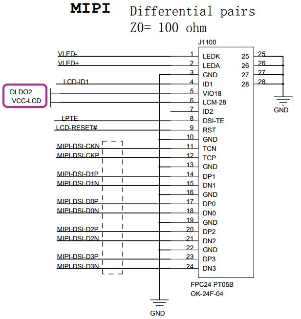
MIPI DSI Connector on PinePhone Schematic (Page 11)
We’ve done quite a bit on our LCD Panel…
Switch on LCD Backlight
Reset LCD Panel to Low
Power on the LCD Panel’s MIPI Display Serial Interface (DSI)
Reset LCD Panel to High
Now it’s time to initialise the Sitronix ST7703 LCD Controller inside the LCD Panel!
We do that by sending 20 Initialisation Commands over MIPI DSI.
What kind of Initialisation Commands?
Here’s a simple Initialisation Command with 4 bytes: pinephone_lcd.c
// Initialization Commands for Sitronix ST7703 LCD Controller:
// Command #1: SETEXTC (ST7703 Page 131)
// Enable USER Command
static const uint8_t g_pinephone_setextc[] = {
  0xb9,  // SETEXTC (ST7703 Page 131): Enable USER Command
  0xf1,  // Enable User command
  0x12,  // (Continued)
  0x83   // (Continued)
};
And here’s a long Initialisation Command with 64 bytes: pinephone_lcd.c
// Command #16: SETGIP1 (ST7703 Page 163)
// Set forward GIP timing
static const uint8_t g_pinephone_setgip1[] = {
  0xe9,  // SETGIP1: Set forward GIP timing
  0x82,  // SHR0, SHR1, CHR, CHR2 refer to Internal DE (REF_EN = 1); (PANEL_SEL = 2)
  0x10,  // Starting position of GIP STV group 0 = 4102 HSYNC (SHR0 Bits 8-12 = 0x10)
  0x06,  // (SHR0 Bits 0-7 = 0x06)
  0x05,  // Starting position of GIP STV group 1 = 1442 HSYNC (SHR1 Bits 8-12 = 0x05)
  0xa2,  // (SHR1 Bits 0-7 = 0xA2)
  0x0a,  // Distance of STV rising edge and HYSNC = 10*2 Fosc (SPON  Bits 0-7 = 0x0A)
  0xa5,  // Distance of STV falling edge and HYSNC = 165*2 Fosc (SPOFF Bits 0-7 = 0xA5)
  ...
We need to send all 20 Initialisation Commands as documented here…
These commands will configure the ST7703 LCD Controller specifically for our Xingbangda XBD599 LCD Panel.
How will we send the Initialisation Commands?
This is how we send the 20 Initialisation Commands to ST7703 LCD Controller over the MIPI DSI Bus: pinephone_lcd.c
// Send 20 Initialisation Commands to ST7703 LCD Controller
int pinephone_lcd_panel_init(void) {

  // For every ST7703 Initialisation Command...
  const int cmd_len = sizeof(g_pinephone_commands) /
                      sizeof(g_pinephone_commands[0]);
  for (int i = 0; i < cmd_len; i++) {

    // Get the ST7703 command and length
    const uint8_t *cmd = g_pinephone_commands[i].cmd;
    const uint8_t len  = g_pinephone_commands[i].len;

    //  If command is null, wait 120 milliseconds
    if (cmd == NULL) {
      up_mdelay(120);
      continue;
    }

    // Send the command to ST7703 over MIPI DSI
    write_dcs(cmd, len);
  }
  return OK;
}What’s g_pinephone_commands?
That’s our Consolidated List of 20 Initialisation Commands: pinephone_lcd.c
// 20 Initialization Commands to be sent to ST7703 LCD Controller
static const struct pinephone_cmd_s g_pinephone_commands[] = {
  { g_pinephone_setextc,      sizeof(g_pinephone_setextc) },
  { g_pinephone_setmipi,      sizeof(g_pinephone_setmipi) },
  { g_pinephone_setpower_ext, sizeof(g_pinephone_setpower_ext) },
  ...
We’re done with the initialisation of the ST7703 LCD Controller inside our LCD Panel! Let’s render something…
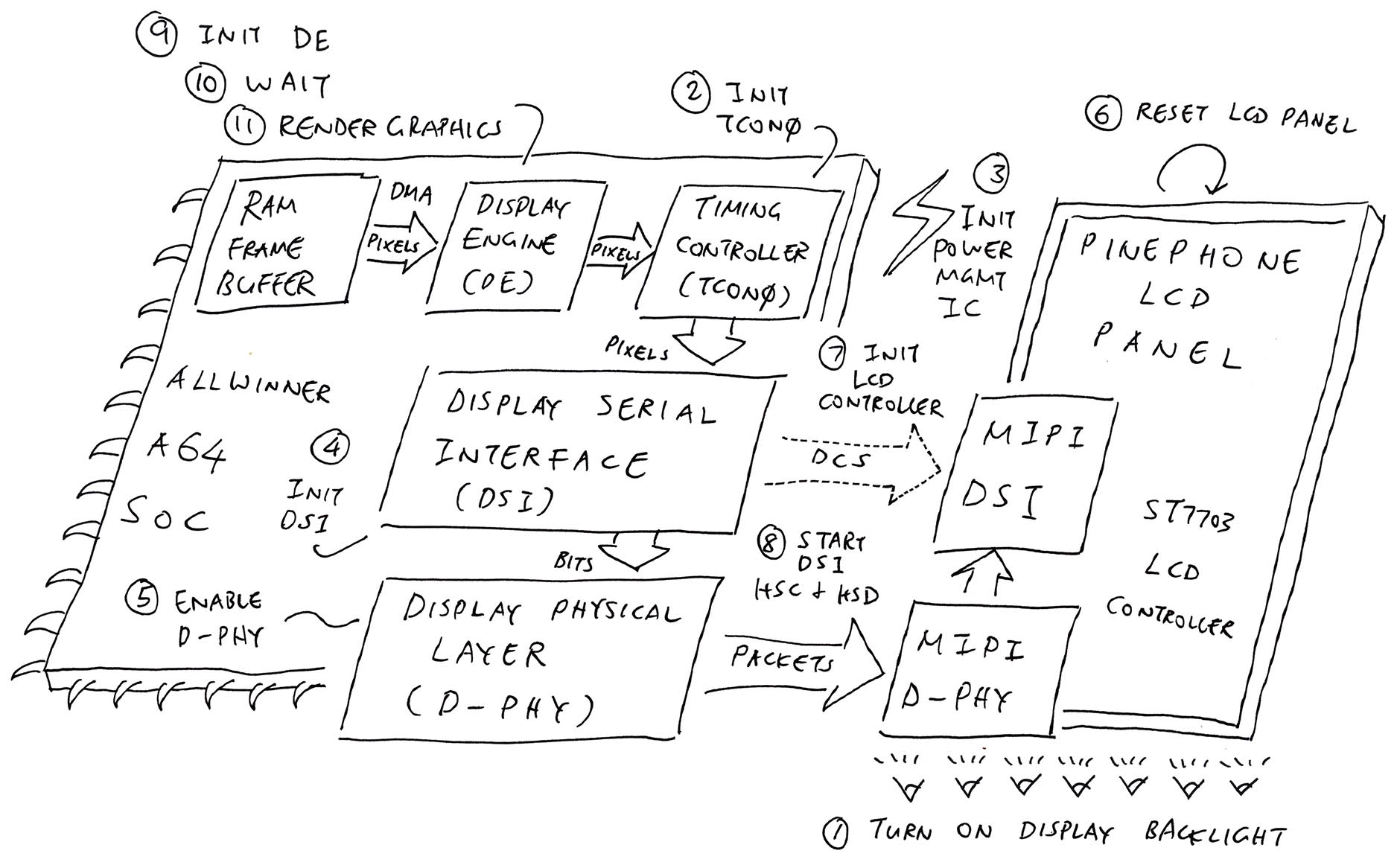
Complete Display Driver for PinePhone
So our LCD Driver will send MIPI DSI Commands to render graphics on PinePhone’s LCD Display?
It gets complicated (pic above)…
At Startup: Our LCD Driver sends MIPI DSI Commands to initialise the ST7703 LCD Controller.
After Startup: Allwinner A64’s Display Engine and Timing Controller (TCON0) will pump pixels continuously to the LCD Panel over MIPI DSI.
(Bypassing our LCD Driver)
Thus our LCD Driver is called only at startup to initialise the LCD Controller (ST7703).
Why so complicated?
Yeah but this Rendering Pipeline is super efficient!
PinePhone doesn’t need to handle Interrupts while rendering the display… Everything is done in Hardware! (Allwinner A64 SoC)
The pixel data is pumped from RAM Framebuffers via Direct Memory Access (DMA). Which is also done in Hardware. (Pic above)
How do we render graphics with Display Engine and Timing Controller TCON0?
Our NuttX Kernel Drivers for Display Engine and Timing Controller TCON0 are explained here…
Let’s find out how the drivers are called at startup.
Complete Display Driver for PinePhone
How is our LCD Driver called at NuttX Startup?
PinePhone needs a super complex Display Driver that will handle 11 steps at startup (pic above)…
We’ve just implemented all 11 steps in the NuttX Kernel… Including the LCD Driver that we saw today.
Here’s how our LCD Driver is called when NuttX boots on PinePhone: pinephone_display.c
// Called by NuttX Kernel at startup
// to start the Display Driver
int up_fbinitialize(int display) {

  // Turn on Display Backlight.
  // BACKLIGHT_BRIGHTNESS_PERCENT is 90
  pinephone_lcd_backlight_enable(BACKLIGHT_BRIGHTNESS_PERCENT);

  // Init Timing Controller TCON0
  a64_tcon0_init(PANEL_WIDTH, PANEL_HEIGHT);

  // Reset LCD Panel to Low
  pinephone_lcd_panel_reset(false);

  // Init PMIC
  pinephone_pmic_init();

  // Wait 15 milliseconds for power supply and power-on init
  up_mdelay(15);
In the code above, we begin with these steps…
Switch on the Display Backlight
Initialise the Timing Controller TCON0
Reset the LCD Panel to Low
Power on the LCD Panel through the Power Management Integrated Circuit (PMIC)
The LCD Panel is powered up, ready to receive MIPI DSI Commands.
  // Enable MIPI DSI
  a64_mipi_dsi_enable();

  // Enable MIPI D-PHY
  a64_mipi_dphy_enable();

  // Reset LCD Panel to High
  pinephone_lcd_panel_reset(true);

  // Wait 15 milliseconds for LCD Panel
  up_mdelay(15);

  // Initialise ST7703 LCD Controller
  pinephone_lcd_panel_init();
Next we…
Enable MIPI Display Serial Interface (DSI) on Allwinner A64 SoC
Enable MIPI Display Physical Layer (D-PHY) on Allwinner A64 SoC
Reset the LCD Panel to High
Send Initialisation Commands to ST7703 LCD Controller over MIPI DSI
Our LCD Controller is all ready to render graphics!
  // Start MIPI DSI Bus in HSC and HSD modes
  a64_mipi_dsi_start();

  // Init Display Engine
  a64_de_init();

  // Wait 160 milliseconds for Display Engine
  up_mdelay(160);

  // Render Framebuffers with Display Engine
  render_framebuffers();
  return OK;
}
Finally to render graphics we…
Start the MIPI DSI Bus for High Speed Clock Mode with High Speed Data Transmission
Initialise the Display Engine on Allwinner A64 SoC
Render the Framebuffers in RAM to the LCD Display over Direct Memory Access (DMA)
When we boot NuttX on PinePhone (via microSD), the Test Pattern appears on PinePhone’s LCD Display! (Pic below)
Here’s the log from our LCD Driver…
Who calls the code above?
In the code above, our function up_fbinitialize executes the 11 steps needed for our PinePhone Display Driver.
At startup, up_fbinitialize is called by fb_register (from the NuttX Framebuffer Driver)…
And fb_register is called by pinephone_bringup, our Startup Function for PinePhone.
Let’s talk about the Framebuffer Driver…
NuttX Kernel calls our LCD Driver to render graphics…
What about NuttX Apps?
NuttX provides a Framebuffer Interface that will be called by NuttX Apps to render graphics…
We’ll talk about the Framebuffer Driver for PinePhone in the next article. (Pic below)
Stay tuned!
Thanks to our new PinePhone LCD Driver, Apache NuttX RTOS now boots with a Test Pattern!
But we’re not done yet! In the next article we’ll talk about the Framebuffer Driver that will allow NuttX Apps to render graphics on PinePhone.
Also we’ll investigate the mystery of the missing pixels. (Pic above)
Please check out the other articles on NuttX for PinePhone…
Many Thanks to my GitHub Sponsors for supporting my work! This article wouldn’t have been possible without your support.
Got a question, comment or suggestion? Create an Issue or submit a Pull Request here…

Testing our PinePhone LCD Driver with a Framebuffer App on Apache NuttX RTOS