📝 23 Dec 2022
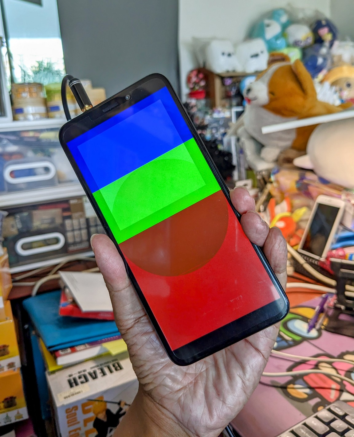
Apache NuttX RTOS for Pine64 PinePhone (pic above) now supports Allwinner A64 Display Engine!
We’re one step closer to completing our NuttX Display Driver for PinePhone.
Let’s find out how our NuttX Display Driver will call A64 Display Engine to render graphics on PinePhone’s LCD Display…
Complete Display Driver for PinePhone
Inside PinePhone’s Allwinner A64 SoC (pic above) is the A64 Display Engine that…
Pulls pixels from Multiple Framebuffers in RAM
(Up to 3 Framebuffers)
Blends the pixels into a single image
(720 x 1440 for PinePhone)
Pushes the image to the A64 Timing Controller TCON0
(Connected via MIPI Display Serial Interface to LCD Display)
Does all this automatically in Hardware via Direct Memory Access (DMA)
(No interrupts needed)
Previously we talked about the A64 Display Engine and coding it with Zig…
Today we’ll program it with the NuttX Kernel Driver for the Display Engine.
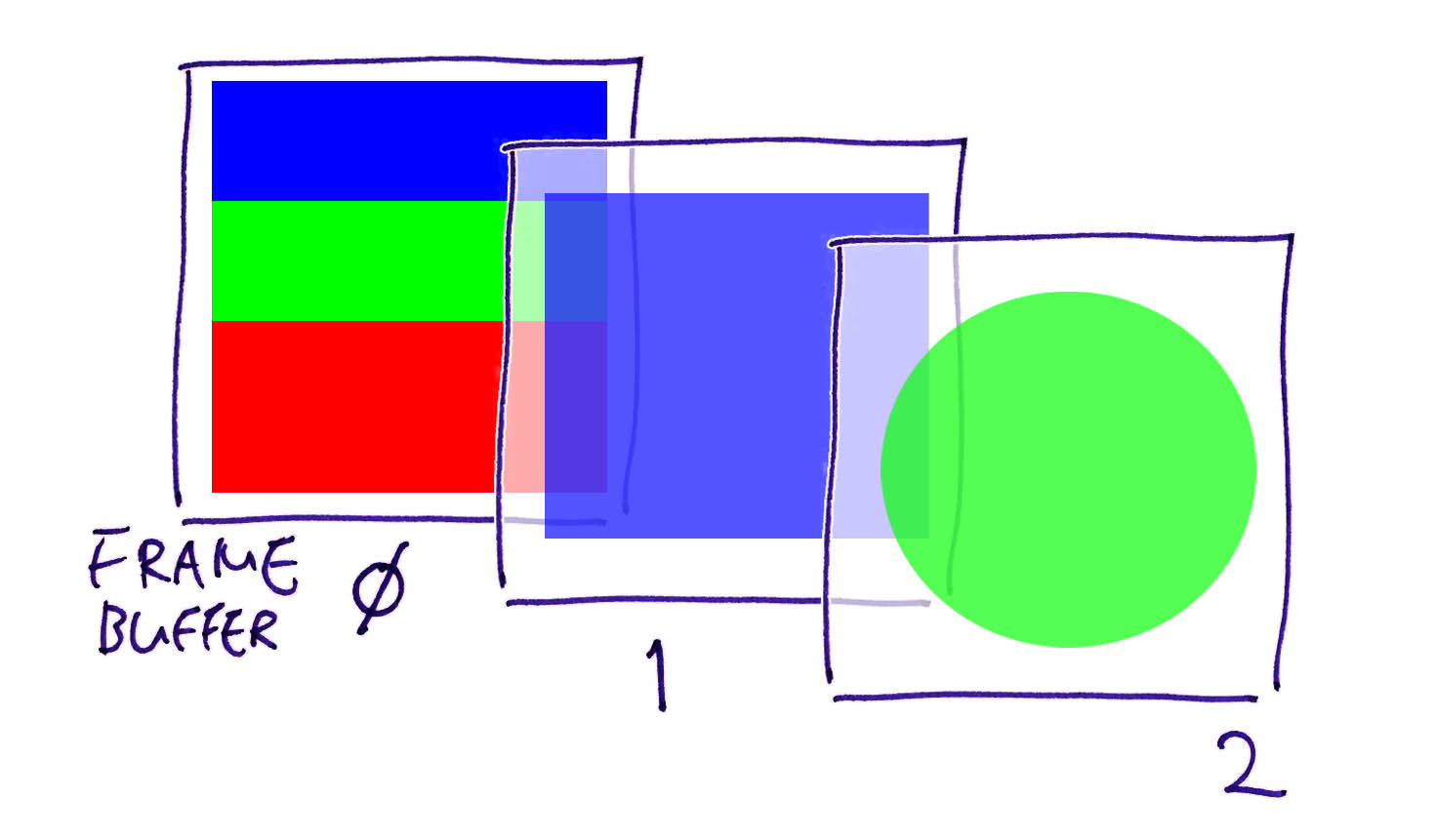
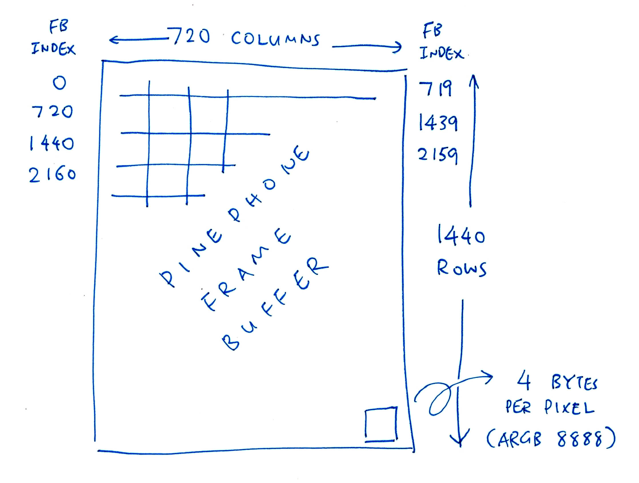
A64 Display Engine supports up to 3 Framebuffers in RAM (pic above). Each pixel has 32-bit ARGB 8888 format.
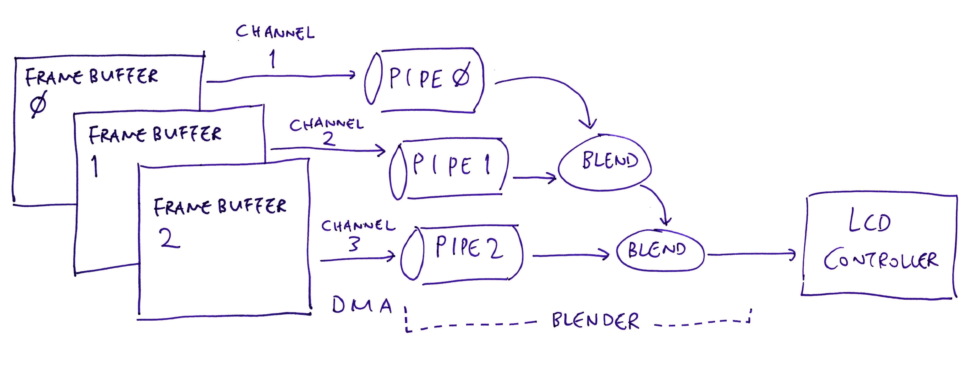
The Display Engine renders the 3 Framebuffer as 3 UI Channels, blended together into the displayed image…
Let’s start with the 3 Framebuffers: test_a64_de.c
Framebuffer 0 (UI Channel 1) is a 720 x 1440 Fullscreen Framebuffer (pic below)…
// PinePhone LCD Panel Width and Height (pixels)
#define PANEL_WIDTH  720
#define PANEL_HEIGHT 1440

// Framebuffer 0: (Base UI Channel)
// Fullscreen 720 x 1440 (4 bytes per XRGB 8888 pixel)
static uint32_t fb0[PANEL_WIDTH * PANEL_HEIGHT];
Later we’ll fill Framebuffer 0 with Blue, Green and Red blocks.
Framebuffer 1 (UI Channel 2) is a 600 x 600 Square…
// Framebuffer 1: (First Overlay UI Channel)
// Square 600 x 600 (4 bytes per ARGB 8888 pixel)
#define FB1_WIDTH  600
#define FB1_HEIGHT 600
static uint32_t fb1[FB1_WIDTH * FB1_HEIGHT];
We’ll fill it with Semi-Transparent White later.
Framebuffer 2 (UI Channel 3) is also a Fullscreen Framebuffer…
// Framebuffer 2: (Second Overlay UI Channel)
// Fullscreen 720 x 1440 (4 bytes per ARGB 8888 pixel)
static uint32_t fb2[PANEL_WIDTH * PANEL_HEIGHT];
We’ll fill it with a Semi-Transparent Green Circle.
Let’s wrap the 3 Framebuffers (fb0, fb1 and fb2) with the NuttX Framebuffer Interface…
NuttX expects our PinePhone Display Driver to provide a Framebuffer Interface for rendering graphics.
Let’s define the NuttX Framebuffer: test_a64_de.c
// TODO: Run `make menuconfig`
// Select "System Type > Allwinner A64 Peripheral Selection > DE"
// Select "System Type > Allwinner A64 Peripheral Selection > RSB"
// Select "Build Setup > Debug Options > Graphics Debug Features > Error + Warnings + Info"
// Select "Build Setup > Debug Options > Battery-related Debug Features > Error + Warnings + Info"
// Select "Device Drivers > Framebuffer Overlay Support"
// Save config and exit menuconfig

// NuttX Framebuffer Interface
#include <nuttx/video/fb.h>

// 3 UI Channels: 1 Base Channel + 2 Overlay Channels
#define CHANNELS 3

// NuttX Video Controller for PinePhone (3 UI Channels)
static struct fb_videoinfo_s videoInfo = {
  .fmt       = FB_FMT_RGBA32,  // Pixel format (XRGB 8888)
  .xres      = PANEL_WIDTH,    // Horizontal resolution in pixel columns
  .yres      = PANEL_HEIGHT,   // Vertical resolution in pixel rows
  .nplanes   = 1,     // Number of color planes supported (Base UI Channel)
  .noverlays = 2      // Number of overlays supported (2 Overlay UI Channels)
};
The fb_videoinfo_s struct defines the overall PinePhone Display Interface…
This is how we define Framebuffer 0 (UI Channel 1): test_a64_de.c
// NuttX Color Plane for PinePhone (Base UI Channel):
// Fullscreen 720 x 1440 (4 bytes per XRGB 8888 pixel)
static struct fb_planeinfo_s planeInfo = {
  .fbmem   = &fb0,         // Start of frame buffer memory
  .fblen   = sizeof(fb0),  // Length of frame buffer memory in bytes
  .stride  = PANEL_WIDTH * 4,  // Length of a line in bytes (4 bytes per pixel)
  .display = 0,   // Display number (Unused)
  .bpp     = 32,  // Bits per pixel (XRGB 8888)
  .xres_virtual = PANEL_WIDTH,   // Virtual Horizontal resolution in pixel columns
  .yres_virtual = PANEL_HEIGHT,  // Virtual Vertical resolution in pixel rows
  .xoffset      = 0,  // Offset from virtual to visible resolution
  .yoffset      = 0   // Offset from virtual to visible resolution
};(fb_planeinfo_s is defined here)
And Framebuffers 1 and 2 (UI Channels 2 and 3): test_a64_de.c
/// NuttX Overlays for PinePhone (2 Overlay UI Channels)
static struct fb_overlayinfo_s overlayInfo[2] = {
  // First Overlay UI Channel:
  // Square 600 x 600 (4 bytes per ARGB 8888 pixel)
  {
    .fbmem     = &fb1,  // Start of frame buffer memory
    .fblen     = sizeof(fb1),  // Length of frame buffer memory in bytes
    .stride    = FB1_WIDTH * 4,  // Length of a line in bytes
    .overlay   = 0,     // Overlay number (First Overlay)
    .bpp       = 32,    // Bits per pixel (ARGB 8888)
    .blank     = 0,     // TODO: Blank or unblank
    .chromakey = 0,     // TODO: Chroma key argb8888 formatted
    .color     = 0,     // TODO: Color argb8888 formatted
    .transp    = { .transp = 0, .transp_mode = 0 },  // TODO: Transparency
    .sarea     = { .x = 52, .y = 52, .w = FB1_WIDTH, .h = FB1_HEIGHT },  // Selected area within the overlay
    .accl      = 0      // TODO: Supported hardware acceleration
  },
  // Second Overlay UI Channel:
  // Fullscreen 720 x 1440 (4 bytes per ARGB 8888 pixel)
  {
    .fbmem     = &fb2,  // Start of frame buffer memory
    .fblen     = sizeof(fb2),  // Length of frame buffer memory in bytes
    .stride    = PANEL_WIDTH * 4,  // Length of a line in bytes
    .overlay   = 1,     // Overlay number (Second Overlay)
    .bpp       = 32,    // Bits per pixel (ARGB 8888)
    .blank     = 0,     // TODO: Blank or unblank
    .chromakey = 0,     // TODO: Chroma key argb8888 formatted
    .color     = 0,     // TODO: Color argb8888 formatted
    .transp    = { .transp = 0, .transp_mode = 0 },  // TODO: Transparency
    .sarea     = { .x = 0, .y = 0, .w = PANEL_WIDTH, .h = PANEL_HEIGHT },  // Selected area within the overlay
    .accl      = 0      // TODO: Supported hardware acceleration
  },
};(fb_overlayinfo_s is defined here)
What’s sarea?
.sarea = {
  .x = 52,
  .y = 52,
  .w = FB1_WIDTH,  // Width is 600
  .h = FB1_HEIGHT  // Height is 600
}
Remember that Framebuffer 1 is 600 pixels wide… But the PinePhone Screen is 720 pixels wide.
We use sarea to specify that Framebuffer 1 will be rendered 52 pixels from the left (X Offset), 52 pixels from the top (Y Offset).
(So it will be centered horizontally)
We’ve defined the NuttX Framebuffers… Let’s render them with the Display Engine!
We’ll walk through the steps…
Initialise Display Engine
Initialise UI Blender
Initialise UI Channels
Enable Display Engine
We begin by initialising the Display Engine…
// Init Display Engine
int ret = a64_de_init();
DEBUGASSERT(ret == OK);

// Wait 160 milliseconds
up_mdelay(160);

// Render Graphics with Display Engine
ret = pinephone_render_graphics();
DEBUGASSERT(ret == OK);a64_de_init comes from our NuttX Kernel Driver for Display Engine.
We call up_mdelay to wait 160 milliseconds. (Explained here)
Then we call pinephone_render_graphics…
Inside pinephone_render_graphics, we initialise the UI Blender that will blend our UI Channels into a single image: test_a64_de.c
// Render graphics with A64 Display Engine
int pinephone_render_graphics(void) {

  // Init the UI Blender for A64 Display Engine
  int ret = a64_de_blender_init();
DEBUGASSERT(ret == OK);(a64_de_blender_init comes from our Display Engine Driver)
Next we initialise UI Channel 1 with Framebuffer 0…
  // Init the Base UI Channel (Channel 1)
  ret = a64_de_ui_channel_init(
    1,  // UI Channel Number (1 for Base UI Channel)
    planeInfo.fbmem,    // Start of Frame Buffer Memory (address should be 32-bit)
    planeInfo.fblen,    // Length of Frame Buffer Memory in bytes
    planeInfo.xres_virtual,  // Horizontal resolution in pixel columns
    planeInfo.yres_virtual,  // Vertical resolution in pixel rows
    planeInfo.xoffset,  // Horizontal offset in pixel columns
    planeInfo.yoffset   // Vertical offset in pixel rows
  );
DEBUGASSERT(ret == OK);(a64_de_ui_channel_init comes from our Display Engine Driver)
Then we initialise UI Channels 2 and 3 (with Framebuffers 1 and 2)…
  // For each of the 2 Overlay UI Channels (Channels 2 and 3)...
  for (int i = 0; i < sizeof(overlayInfo) / sizeof(overlayInfo[0]); i++) {

    // Get the NuttX Framebuffer for the UI Channel
    const struct fb_overlayinfo_s *ov = &overlayInfo[i];

    // Init the UI Channel.
    // We pass NULL if the UI Channel should be disabled.
    ret = a64_de_ui_channel_init(
      i + 2,  // UI Channel Number (2 and 3 for Overlay UI Channels)
      (CHANNELS == 3) ? ov->fbmem : NULL,  // Start of Frame Buffer Memory (address should be 32-bit)
      ov->fblen,    // Length of Frame Buffer Memory in bytes
      ov->sarea.w,  // Horizontal resolution in pixel columns
      ov->sarea.h,  // Vertical resolution in pixel rows
      ov->sarea.x,  // Horizontal offset in pixel columns
      ov->sarea.y   // Vertical offset in pixel rows
    );
    DEBUGASSERT(ret == OK);
}(a64_de_ui_channel_init comes from our Display Engine Driver)
Finally we enable the Display Engine…
  // Set UI Blender Route, enable Blender Pipes
  // and apply the settings
  ret = a64_de_enable(CHANNELS);
DEBUGASSERT(ret == OK); (a64_de_enable comes from our Display Engine Driver)
The Display Engine starts pulling pixels from our Framebuffers over Direct Memory Access (DMA). And pushes the rendered image to PinePhone’s LCD Display.
But we won’t see anything until we populate our 3 Framebuffers with a Test Pattern…
  // Fill Framebuffer with Test Pattern.
  // Must be called after Display Engine is Enabled,
  // or missing rows will appear.
  test_pattern();
  return OK;
}
Let’s do a simple Test Pattern…
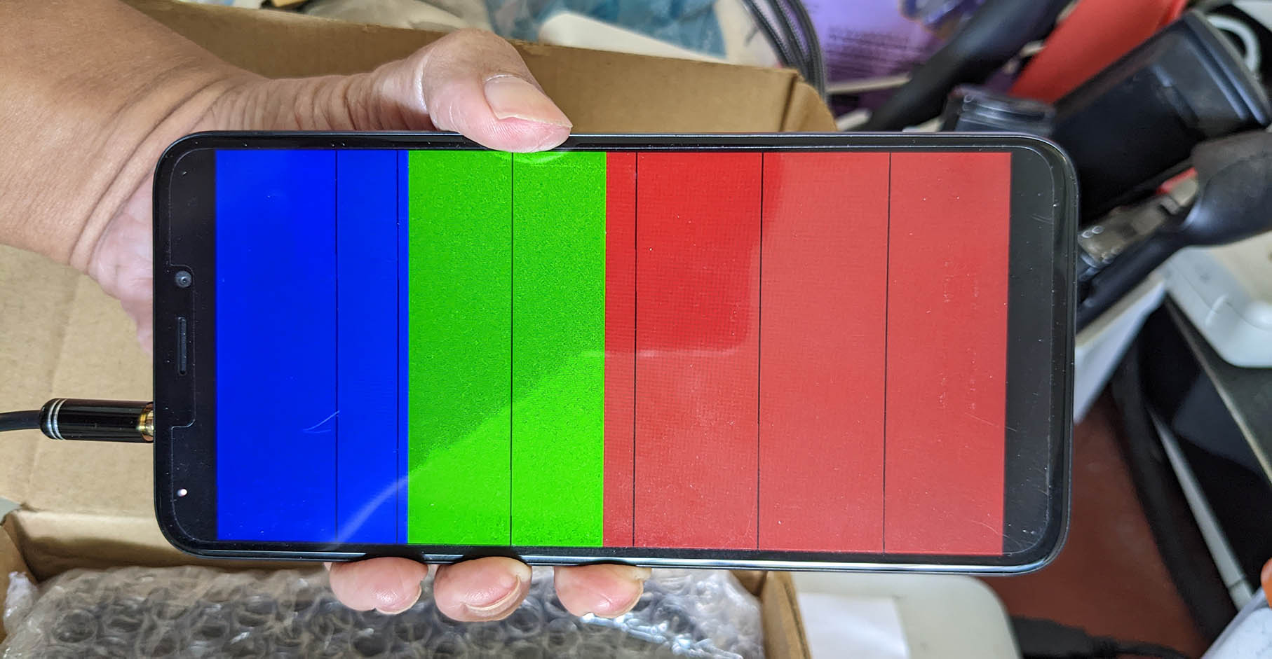
We fill our 3 Framebuffers with a simple Test Pattern (pic above)…
Framebuffer 0: Blue, Green and Red Blocks
(720 x 1440 pixels)
Framebuffer 1: Semi-Transparent White Square
(600 x 600 pixels)
Framebuffer 2: Semi-Transparent Green Circle
(720 x 1440 pixels)
Note that Framebuffers 1 and 2 are Semi-Transparent, to show that the UI Blender works correctly.
This is how we populate our 3 Framebuffers: test_a64_de.c
// Fill the Framebuffers with a Test Pattern.
// Must be called after Display Engine is Enabled,
// or missing rows will appear.
static void test_pattern(void) {

  // Zero the Framebuffers
  memset(fb0, 0, sizeof(fb0));
  memset(fb1, 0, sizeof(fb1));
  memset(fb2, 0, sizeof(fb2));
Framebuffer 0 (UI Channel 1) will have Blue, Green and Red Blocks…
  // Init Framebuffer 0:
  // Fill with Blue, Green and Red
  const int fb0_len = sizeof(fb0) / sizeof(fb0[0]);

  // For every pixel...
  for (int i = 0; i < fb0_len; i++) {

    // Colours are in XRGB 8888 format
    if (i < fb0_len / 4) {
      // Blue for top quarter
      fb0[i] = 0x80000080;
    } else if (i < fb0_len / 2) {
      // Green for next quarter
      fb0[i] = 0x80008000;
    } else {
      // Red for lower half
      fb0[i] = 0x80800000;
    }

    // Fixes the missing rows, not sure why
    ARM64_DMB(); ARM64_DSB(); ARM64_ISB();
  }
(We’ll talk about ARM64_DMB later)
Framebuffer 1 (UI Channel 2) will be Semi-Transparent White…
  // Init Framebuffer 1:
  // Fill with Semi-Transparent White
  const int fb1_len = sizeof(fb1) / sizeof(fb1[0]);

  // For every pixel...
  for (int i = 0; i < fb1_len; i++) {

    // Set the pixel to Semi-Transparent White
    fb1[i] = 0x40FFFFFF;  // ARGB 8888 format

    // Fixes the missing rows, not sure why
    ARM64_DMB(); ARM64_DSB(); ARM64_ISB();
  }
And Framebuffer 2 (UI Channel 3) will have a Semi-Transparent Green Circle…
  // Init Framebuffer 2:
  // Fill with Semi-Transparent Green Circle
  const int fb2_len = sizeof(fb2) / sizeof(fb2[0]);

  // For every pixel row...
  for (int y = 0; y < PANEL_HEIGHT; y++) {

    // For every pixel column...
    for (int x = 0; x < PANEL_WIDTH; x++) {

      // Get pixel index
      const int p = (y * PANEL_WIDTH) + x;
      DEBUGASSERT(p < fb2_len);

      // Shift coordinates so that centre of screen is (0,0)
      const int half_width  = PANEL_WIDTH  / 2;
      const int half_height = PANEL_HEIGHT / 2;
      const int x_shift = x - half_width;
      const int y_shift = y - half_height;

      // If x^2 + y^2 < radius^2, set the pixel to Semi-Transparent Green
      if (x_shift*x_shift + y_shift*y_shift < half_width*half_width) {
        fb2[p] = 0x80008000;  // Semi-Transparent Green in ARGB 8888 Format
      } else {  // Otherwise set to Transparent Black
        fb2[p] = 0x00000000;  // Transparent Black in ARGB 8888 Format
      }

      // Fixes the missing rows, not sure why
      ARM64_DMB(); ARM64_DSB(); ARM64_ISB();
    }
  }
}
We’re done with our Test Pattern! Let’s talk about ARM64_DMB…
Why the Arm Barriers?
// Fixes the missing rows, not sure why
ARM64_DMB(); ARM64_DSB(); ARM64_ISB();
These are Arm64 Barrier Instructions that prevent caching and out-of-order execution. (See this)
If we omit these Barrier Instructions, the rendered image will have missing rows. (Pic above)
We’re not sure why this happens. Maybe it’s the CPU Cache? DMA? Framebuffer Alignment? Memory Corruption?
(Doesn’t happen in the original Zig version)
Why do we fill the Framebuffers after enabling the Display Engine?
Since we’re running on DMA (Direct Memory Access), rightfully we can fill the Framebuffers (with our Test Pattern) before enabling the Display Engine…
But this creates mysterious missing rows (pic above). So we fill the Framebuffers after enabling the Display Engine.
Let’s run our Test Code…
(We’re still missing a row at the bottom of the circle)
Complete Display Driver for PinePhone
Are we done yet with our Display Driver for PinePhone?
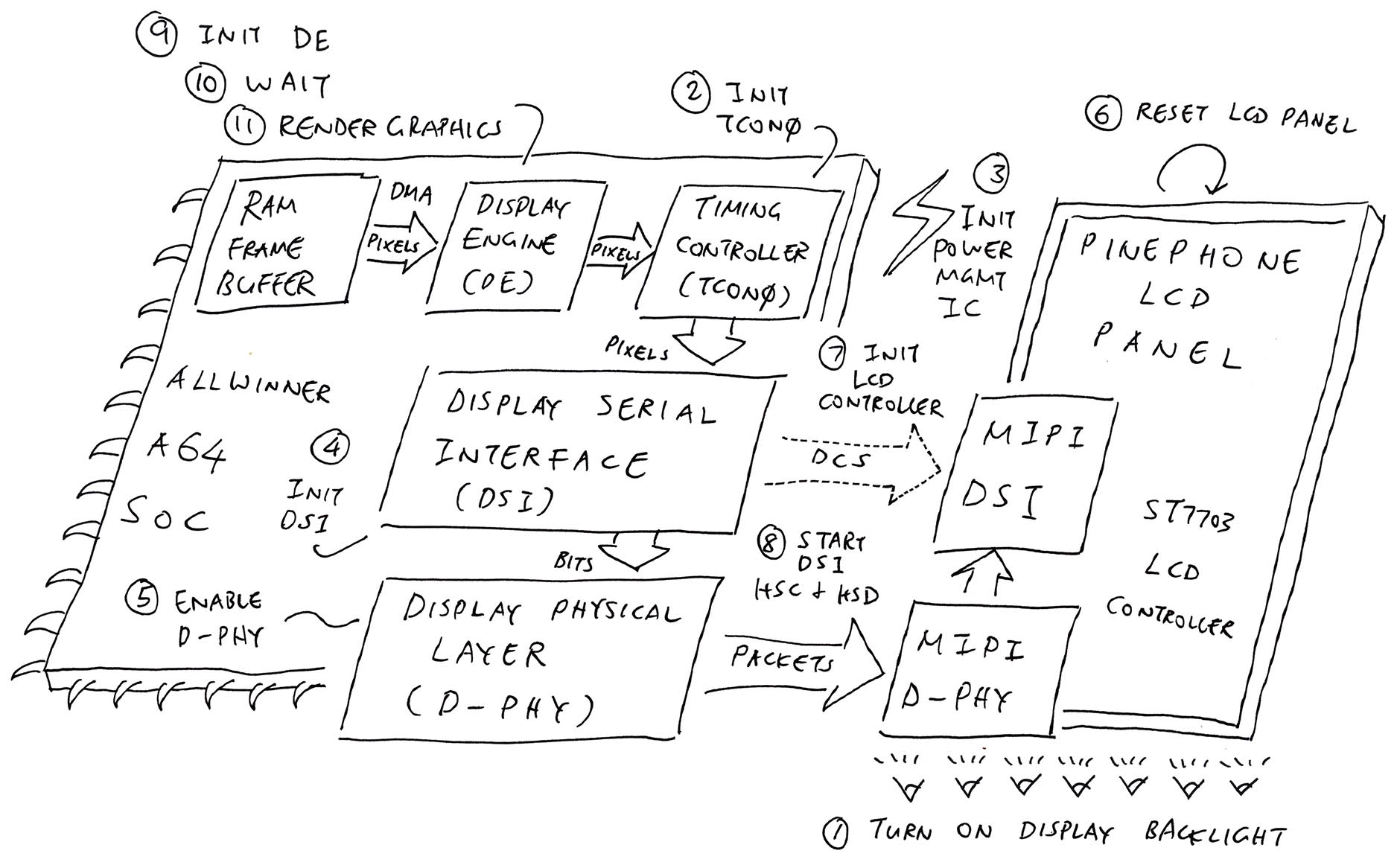
Not quite! PinePhone needs a super complex Display Driver that will handle 11 steps (pic above)…
We’ve implemented most of this in the NuttX Kernel, we’re now converting the remaining bits from Zig to C.
So how do we test this hodgepodge of Zig and C?
We created a Zig Test Program that glues together the Zig and C bits for testing.
Here are all 11 steps of our upcoming Display Driver, hodgepodged with Zig: render.zig
// Zig Test Program that renders 3 UI Channels in Zig and C...
// Turn on PinePhone Display Backlight (in Zig)
backlight.backlight_enable(90);  // 90% brightness

// Init A64 Timing Controller TCON0 (in C)
// PANEL_WIDTH is 720, PANEL_HEIGHT is 1440
_ = a64_tcon0_init(PANEL_WIDTH, PANEL_HEIGHT);

// Init PinePhone Power Management Integrated Circuit (in C)
_ = pinephone_pmic_init();

// Wait 15 milliseconds for power supply and power-on init
up_mdelay(15);
In the code above, we do these steps…
Turn on PinePhone’s Display Backlight
Initialise the A64 Timing Controller TCON0
(a64_tcon0_init comes from our NuttX Driver for Timing Controller TCON0)
Initialise PinePhone’s Power Management Integrated Circuit (PMIC) to power on the LCD Panel
Wait 15 milliseconds
// Enable A64 MIPI Display Serial Interface (in C)
_ = a64_mipi_dsi_enable();

// Enable A64 MIPI Display Physical Layer (in C)
_ = a64_mipi_dphy_enable();
Here we enable the A64 MIPI Display Serial Interface and MIPI Display Physical Layer.
(a64_mipi_dsi_enable comes from our NuttX Driver for MIPI Display Serial Interface)
// Reset LCD Panel (in Zig)
panel.panel_reset();

// Wait 15 milliseconds for LCD Panel
up_mdelay(15);

// Init LCD Panel (in C)
_ = pinephone_panel_init();
Next we reset the LCD Panel, wait 15 milliseconds and send the Initialisation Commands to the LCD Controller.
(pinephone_panel_init will be added to NuttX Kernel)
(Which calls a64_mipi_dsi_write from our NuttX Driver for MIPI Display Serial Interface)
// Start A64 MIPI Display Serial Interface (in C)
_ = a64_mipi_dsi_start();
We start A64’s MIPI Display Serial Interface.
(a64_mipi_dsi_start comes from our NuttX Driver for MIPI Display Serial Interface)
// Init A64 Display Engine (in C)
_ = a64_de_init();

// Wait 160 milliseconds for Display Engine
up_mdelay(160);
We initialise the Display Engine.
(We’ve seen a64_de_init earlier)
// Render Graphics with Display Engine (in C)
_ = pinephone_render_graphics();
Finally we render the framebuffers with the Display Engine.
(We’ve seen pinephone_render_graphics earlier)
This is how we compile our Zig Test Program…
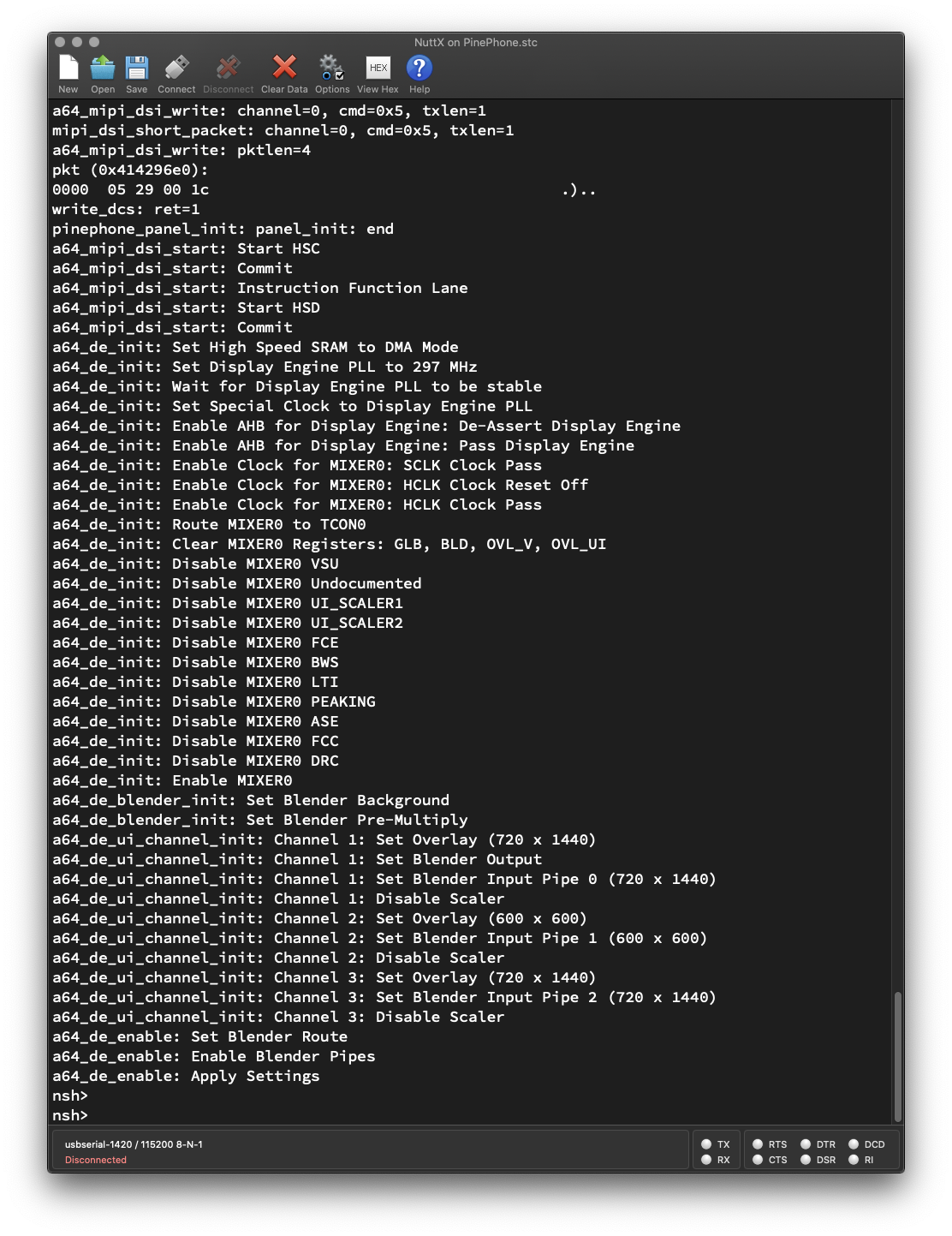
We boot NuttX on PinePhone (with a microSD Card) and run our Zig Test Program…
NuttShell (NSH) NuttX-11.0.0-pinephone

nsh> uname -a
NuttX 11.0.0-pinephone 64a54d2-dirty
Dec 21 2022 21:48:25 arm64 pinephone

nsh> hello 0PinePhone renders our Test Pattern on the LCD Display (pic below). Yep our (work-in-progress) PinePhone Display Driver has been tested successfully!
Here’s the Debug Log from our Zig Test Program…
Won’t the Debug Logging create extra latency that might affect the driver?
That’s why we also test with Debug Logging disabled…
Let’s talk about the upcoming drivers that we’re adding to NuttX Kernel…
Which bits of our NuttX Display Driver are still in Zig?
These parts are still in Zig, pending conversion to C…
Driver for PinePhone Display Backlight
Driver for PinePhone LCD Panel
These have just been converted from Zig to C, now adding to NuttX Kernel…
Driver for PinePhone Power Management Integrated Circuit (PMIC)
Driver for A64 Reduced Serial Bus (RSB)
(Needed for PinePhone PMIC)
Where will the new drivers live inside the NuttX Kernel?
The drivers for Display Backlight, LCD Panel and PMIC will go into the new PinePhone LCD Driver.
Which will follow the design of the STM32F7 LCD Driver in NuttX…
At startup, stm32_bringup calls fb_register
To initialise the Framebuffer, fb_register calls up_fbinitialize
To initialise the Display Driver, up_fbinitialize calls stm32_ltdcinitialize
Inside the Display Driver, stm32_ltdcinitialize creates the NuttX Framebuffer
NuttX Framebuffer is here: stm32_ltdc.c
Our new PinePhone LCD Driver shall execute all 11 steps as described earlier…
Probably inside our new implementation of up_fbinitialize. Work-in-progress…
Very soon the official NuttX Kernel will be rendering graphics on PinePhone’s LCD Display… Stay tuned for updates!
Please check out the other articles on NuttX for PinePhone…
Many Thanks to my GitHub Sponsors for supporting my work! This article wouldn’t have been possible without your support.
Got a question, comment or suggestion? Create an Issue or submit a Pull Request here…
Can we call sleep() or usleep() in our NuttX Display Driver?
Sorry Nope! Most of our Display Driver code runs in the NuttX Kernel at startup.
Calling sleep() or usleep() will crash the kernel…
Because the kernel is still starting up!
So how do we wait a while in our NuttX Display Driver?
We call up_mdelay() like so…
// Wait 160 milliseconds
up_mdelay(160);
How does up_mdelay() work?
It’s a very simple loop: arm64_assert.c
// Wait for the specified milliseconds
void up_mdelay(unsigned int milliseconds) {
  volatile unsigned int i;
  volatile unsigned int j;

  for (i = 0; i < milliseconds; i++) {
    for (j = 0; j < CONFIG_BOARD_LOOPSPERMSEC; j++) {
    }
  }
}
Huh? Won’t the compiler optimise the code and remove the loop?
It won’t because we declared the variables as volatile.
The NuttX Disassembly shows that the loop is still intact: nuttx.S
arm64_assert.c:69 (discriminator 2)
  for (i = 0; i < milliseconds; i++)
    40081830:	b9400be1 	ldr	w1, [sp, #8]
    40081834:	11000421 	add	w1, w1, #0x1
    40081838:	b9000be1 	str	w1, [sp, #8]
    4008183c:	17fffff4 	b	4008180c <up_mdelay+0x10>
arm64_assert.c:71 (discriminator 3)
      for (j = 0; j < CONFIG_BOARD_LOOPSPERMSEC; j++)
    40081840:	b9400fe1 	ldr	w1, [sp, #12]
    40081844:	11000421 	add	w1, w1, #0x1
    40081848:	b9000fe1 	str	w1, [sp, #12]
    4008184c:	17fffff6 	b	40081824 <up_mdelay+0x28>
What’s CONFIG_BOARD_LOOPSPERMSEC?
That’s a magic constant computed by the NuttX Calibration Tool For udelay.
To install the calibration tool…
make menuconfigThen select…
Application Configuration > Examples > Calibration Tool For udelay And rebuild NuttX.
Boot NuttX on PinePhone and run calib_udelay…
nsh> calib_udelay

Calibrating timer for main calibration...
Performing main calibration for udelay.This will take approx. 17.280 seconds.
Calibration slope for udelay:
  Y = m*X + b, where
    X is loop iterations,
    Y is time in nanoseconds,
    b is base overhead,
    m is nanoseconds per loop iteration.

  m = 8.58195489 nsec/iter
  b = -347067.66917297 nsec

  Correlation coefficient, R² = 1.0000

Without overhead, 0.11652356 iterations per nanosecond and 116523.57 iterations per millisecond.

Recommended setting for CONFIG_BOARD_LOOPSPERMSEC:
CONFIG_BOARD_LOOPSPERMSEC=116524We update the NuttX Board Configuration for PinePhone with the computed value: pinephone/configs/nsh/defconfig
CONFIG_BOARD_LOOPSPERMSEC=116524(PinePhone is probably the fastest NuttX Board ever!)
What if our driver needs to wait a while AFTER the NuttX Kernel has been started?
Call nxsig_usleep() instead.
It suspends the current thread, instead of doing a busy-wait loop.