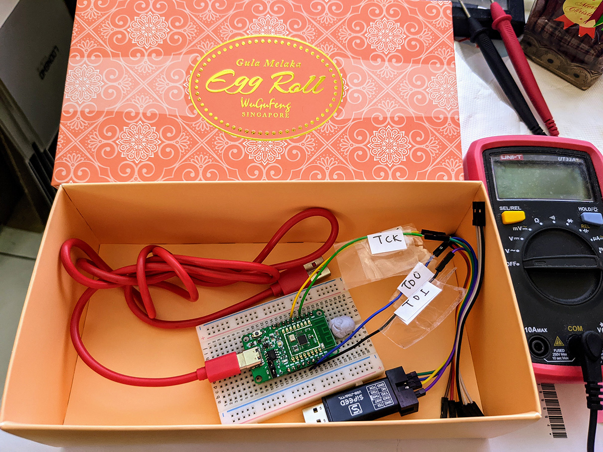
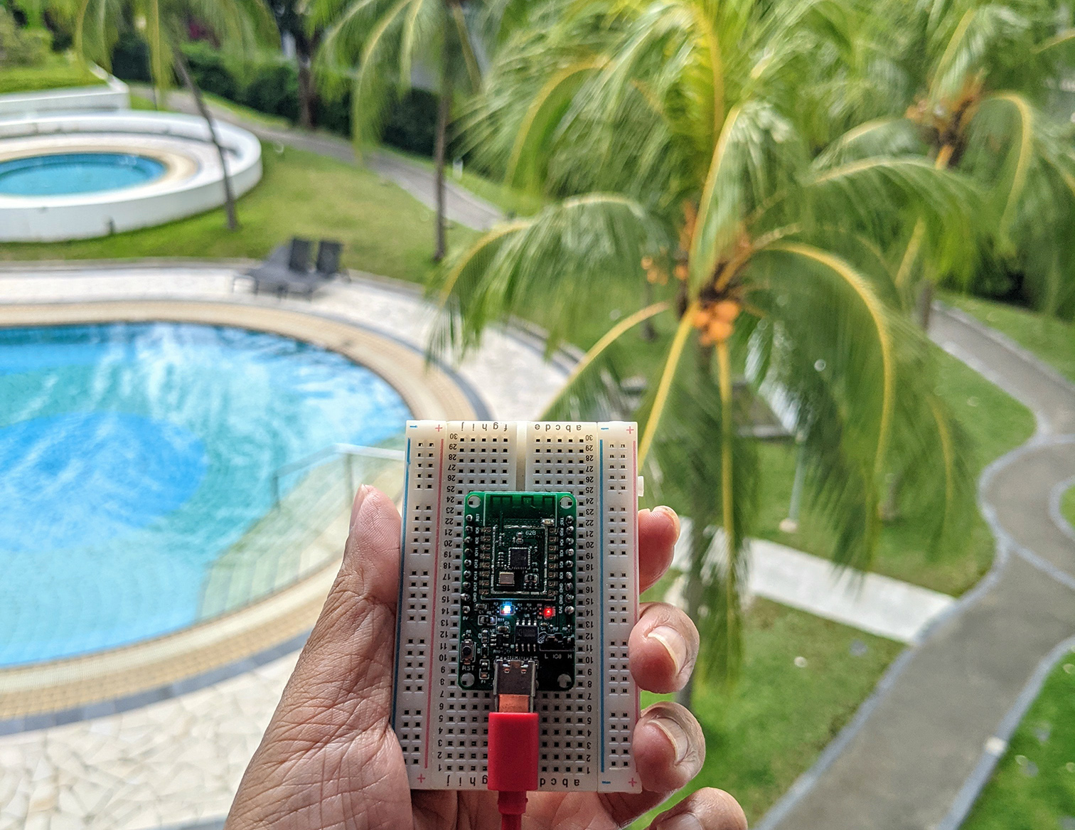
PineCone BL602 RISC-V Evaluation Board connected to Sipeed JTAG Debugger
📝 11 Dec 2020
Today we’ll learn to connect the PineCone BL602 RISC-V Evaluation Board to OpenOCD for loading and debugging PineCone firmware.
(JTAG and OpenOCD won’t work for flashing BL602)
(UPDATE: There’s a new doc on BL602, OpenOCD and GDB. Check it out here
OpenOCD is the open source software that runs on our computer and connects to microcontrollers (like PineCone) to…
Load our firmware to the microcontroller’s RAM
Debug our firmware: Set breakpoints, step through code, examine the variables
Most development tools (like VSCode) work with OpenOCD for loading and debugging firmware.
Thus it’s important to get PineCone talking to OpenOCD, so that our development tools will work with PineCone.
(Rust for PineCone also uses OpenOCD for loading and debugging)
PineCone exposes a JTAG Port that works with OpenOCD for loading and debugging firmware.
(JTAG and OpenOCD won’t work for flashing BL602)
This is similar to the SWD Port that’s found in PineTime, STM32 Blue Pill and other Arm microcontrollers.
We’ll learn about JTAG in the next section.
Doesn’t PineCone support UART flashing? Why use OpenOCD and JTAG?
Yes we may flash our firmware to PineCone via a Serial USB connection to PineCone’s UART Port. More about this
However it uses a flashing protocol that’s designed specifically for BL602 devices. The flashing protocol is not supported by popular tools like VSCode.
BL602 doesn’t support debugging over UART. For serious firmware coding on BL602, OpenOCD is the best option.
(JTAG and OpenOCD won’t work for flashing BL602)
OpenOCD has been around for a while. Are there newer tools for loading and debugging firmware?
There’s a newer alternative to OpenOCD that’s built with Rust: probe.rs
It has beta support for JTAG. Hopefully we can use it with PineCone someday.
But for today, we’ll learn to use OpenOCD and JTAG with PineCone.
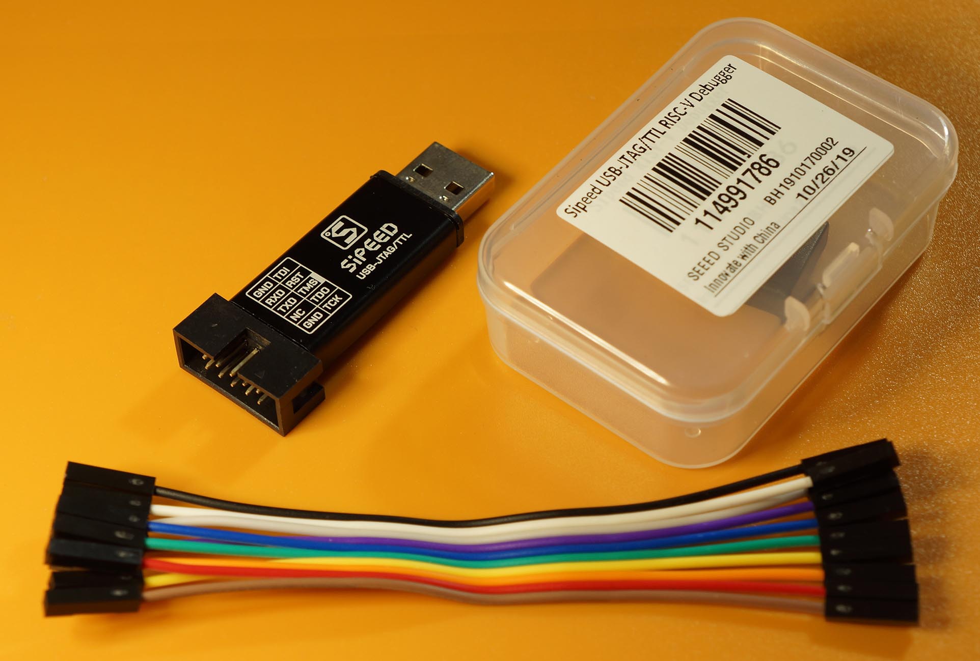
Sipeed JTAG Debugger with the JTAG Pins: TMS, TCK, TDI, TDO, GND
PineCone’s JTAG Port is a standard port for loading and debugging firmware, available on most RISC-V microcontrollers (like SiFive FE310 and GigaDevice GD32 VF103).
JTAG uses these pins…
(If you stare at it… Yep JTAG looks like SPI!)
We’ll connect the JTAG Port on PineCone to our computer with a JTAG Debugger, like the Sipeed JTAG Debugger shown above.
Why are the JTAG Pins named “Test”?
Because JTAG was originally created for testing Printed Circuit Boards. JTAG stands for Joint Test Action Group, the maintainers of the JTAG standard.
Is SWD supported for flashing and debugging firmware on PineCone?
Sorry no. SWD is available only on Arm Microcontrollers. (SWD was created by Arm)
SWD is derived from JTAG… It takes the 4 pins from JTAG and smashes them into 2 pins SWDCLK (Clock) and SWDIO (Birectional Data). More details
Let’s go deep into the JTAG Port on PineCone…
Default JTAG Port on PineCone
BL602 is an interesting microcontroller… Each pin may be remapped to various functions: GPIO, SPI, I2C, UART, PWM, ADC, SDIO, even JTAG!
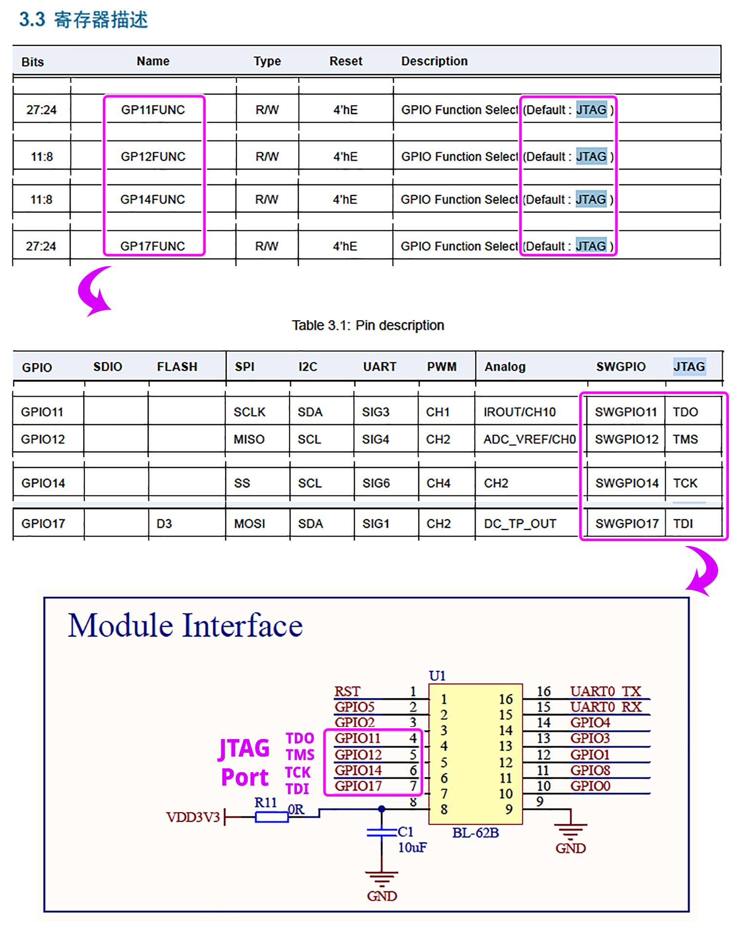
To find the default JTAG Pins, we refer to…
Section 3.2.8, “GPIO Function” (Pages 27 to 40)
“Module Interface”
(See the pic above)
Based on the above docs, the JTAG Port is located at the following pins whenever we boot or reset PineCone…
| JTAG Pin | PineCone Pin |
|---|---|
TDO | IO 11 |
TMS | IO 12 |
TCK | IO 14 |
TDI | IO 17 |
GND | GND |
Before connecting PineCone to our JTAG Debugger, we need to solder the headers to the PineCone board and expose the above JTAG Pins.
Default JTAG Port connected to JTAG Debugger. Jumper is set to H, for Bootloader Mode. LED is lit with multiple colours when JTAG is active.
The instructions here will work with Sipeed JTAG Debugger and other JTAG Debuggers based on FTDI FT2232.
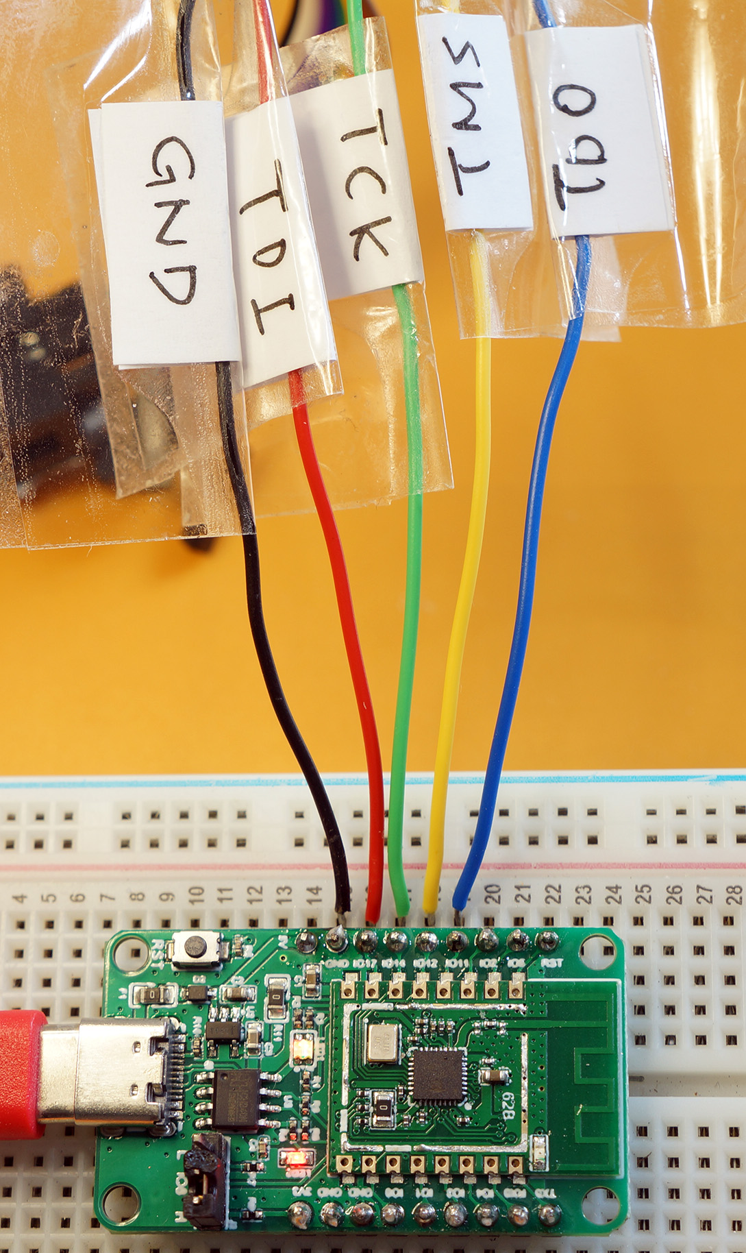
Now we connect the JTAG Debugger to PineCone…
Connect our JTAG Debugger to the PineCone Pins
| JTAG Debugger | PineCone Pin | Wire Colour |
|---|---|---|
TDO | IO 11 | Blue |
TMS | IO 12 | Yellow |
TCK | IO 14 | Green |
TDI | IO 17 | Red |
GND | GND | Black |
(See pic above)
Connect the JTAG Debugger to our computer’s USB Port
Connect PineCone to our computer’s USB Port
(Yes we’ll need two USB ports on our computer)
Follow these instructions to install the FT2232 drivers for Linux, macOS and Windows…
For Windows: Follow the steps above. Then use the Zadig Tool to install the WinUSB Driver for BOTH Dual RS232 (Interface 0) and Dual RS232 (Interface 1)
We’re ready to download and run OpenOCD…
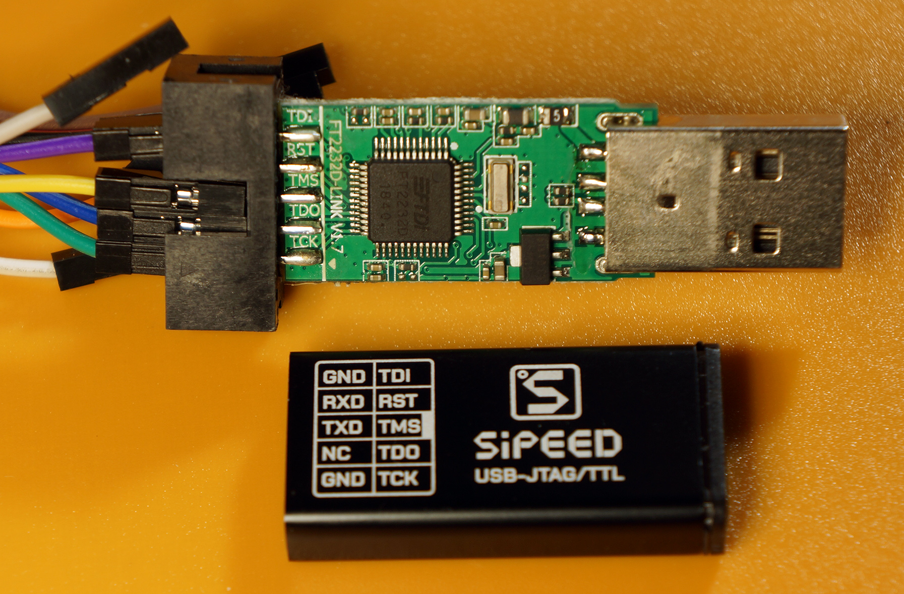
Sipeed JTAG Debugger is powered by FTDI FT2232D
Here are the steps to download and run OpenOCD with PineCone on Linux, macOS and Windows…
Download OpenOCD from the xPack OpenOCD site… (Other variants of OpenOCD may not work with PineCone)
Extract the downloaded file. On Windows: Use 7-Zip
Open a command prompt and enter…
git clone --recursive https://github.com/lupyuen/pinecone-rustIf we will be coding Rust Firmware for PineCone, enter these commands too…
git clone --recursive https://github.com/sipeed/bl602-pac
git clone --recursive https://github.com/sipeed/bl602-halAt the command prompt, enter…
cd pinecone-rust
OPENOCD_DIRECTORY/bin/openocd
For Windows: Enter…
cd pinecone-rust
OPENOCD_DIRECTORY\bin\openocd
Change OPENOCD_DIRECTORY to the directory that contains the extracted xPack OpenOCD files.
We should see this output in OpenOCD…
xPack OpenOCD, x86_64 Open On-Chip Debugger 0.10.0+dev-00378-ge5be992df (2020-06-26-12:31)
Licensed under GNU GPL v2
For bug reports, read
        http://openocd.org/doc/doxygen/bugs.html
Ready for Remote Connections
Info : clock speed 100 kHz
Info : JTAG tap: riscv.cpu tap/device found: 0x20000c05 (mfg: 0x602 (<unknown>), part: 0x0000, ver: 0x2)
Notice the mysterious number 0x20000c05?
This is very important… 0x20000c05 is the CPU ID that identifies the BL602 Microcontroller. It shows that our JTAG connection is OK.
If we see any CPU ID other than 0x20000c05, it probably means that our JTAG connection is loose. Or that we have connected our JTAG Debugger to the incorrect PineCone Pins.
Info : datacount=1 progbufsize=2
Info : Disabling abstract command reads from CSRs.
Info : Examined RISC-V core; found 1 harts
Info :  hart 0: XLEN=32, misa=0x40801125
Info : starting gdb server for riscv.cpu.0 on 3333
Info : Listening on port 3333 for gdb connections
Then we see some info about PineCone’s BL602 Microcontroller. And we see that OpenOCD is ready to accept debugging commands from GDB.
Info : JTAG tap: riscv.cpu tap/device found: 0x20000c05 (mfg: 0x602 (<unknown>), part: 0x0000, ver: 0x2)
reset-assert-pre
reset-deassert-post
Info : Disabling abstract command writes to CSRs.
reset-init
Info : Listening on port 6666 for tcl connections
Finally OpenOCD restarts the JTAG connection. And it listens for OpenOCD (TCL) commands.
If we see CPU ID 0x20000c05 and the messages above… Congratulations OpenOCD is now connected to PineCone’s JTAG Port!
OpenOCD is all ready to load and debug PineCone firmware. (Which we’ll cover in the next article)
To stop OpenOCD and disconnect from PineCone, press Ctrl-C.
If we see…
Error: unable to open ftdi device with vid 0403, pid 6010, description '*', serial '*' at bus location '*'It means that OpenOCD couldn’t detect the JTAG Debugger. Check that the FT2232 drivers are installed correctly.
If we see…
Error: failed read at 0x11, status=1
Error: Hart 0 is unavailable.
Error: Hart 0 doesn't exist.
Info : Hart 0 unexpectedly reset!
Error: failed read at 0x11, status=1
Check that the GND Pin is connected from the JTAG Debugger to PineCone.
More tips on connecting OpenOCD to FT2232
The OpenOCD connection to PineCone is controlled by the OpenOCD Script pinecone-rust/openocd.cfg.
Our OpenOCD Script is based on the one kindly contributed by the Sipeed BL602 Community.
Let’s study the important bits of our OpenOCD Script: pinecone-rust/openocd.cfg
## Uncomment to enable debug messages
## debug_level 4
To show debug messages in OpenOCD, uncomment the debug_level line. (Remove the leading “#”)
This is useful for troubleshooting the OpenOCD connection to PineCone. OpenOCD will show every single JTAG packet transmitted between our computer and PineCone.
adapter driver ftdi

ftdi_vid_pid 0x0403 0x6010
Here we tell OpenOCD to use the FT2232 debugger that’s connected to USB.
0x0403 is the USB Vendor ID for FT2232. 0x6010 is the USB Product ID.
## Sipeed JTAG Debugger uses FTDI Channel 0, not 1
ftdi_channel 0
## Previously: ftdi_channel 1
According to the FT2232 Specs, the FT2232 module supports two Serial Channels: 0 and 1.
For Sipeed JTAG Debugger: The FTDI Channel must be 0. See the schematics
For other JTAG Debuggers: Set the FTDI Channel to 0 if PineCone is connected to the first Serial Channel, and to 1 for the second Serial Channel.
transport select jtag

## TODO: Increase the adapter speed (now 100 kHz)
adapter speed 100
## Previously: adapter speed 2000
Here we select JTAG as the communication protocol for talking to PineCone.
Our OpenOCD Script talks to PineCone at 100 kbps, which is a safe (but slow) data rate that works with most JTAG Debuggers.
We should increase the Adapter Speed to speed up the data transfer. (After lots of testing, of course)
set _CHIPNAME riscv
jtag newtap $_CHIPNAME cpu -irlen 5 -expected-id 0x20000c05
This is the part that verifies BL602’s CPU ID: 0x20000c05
This should never be changed. (Unless we’re connecting to a different microcontroller)
init
reset init
The init command initiates the JTAG connection to PineCone, and verifies the CPU ID of our BL602 Microcontroller.
reset init triggers a reboot of PineCone. (Similar to pressing the RST button on PineCone)
After executing our script, OpenOCD waits to receive GDB Debugging commands and OpenOCD TCL commands.
For some OpenOCD Scripts (like for loading firmware), we don’t need OpenOCD to wait for further commands. In such scripts, we terminate OpenOCD with the exit command…
# Terminate OpenOCD
exit
See the complete OpenOCD Script: pinecone-rust/openocd.cfg
Check out the awesome work on PineCone OpenOCD by @gamelaster
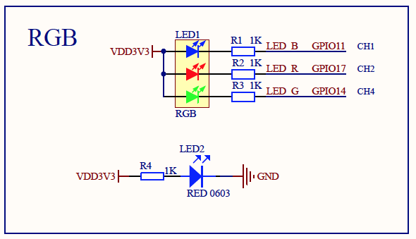
PineCone LED uses GPIO 11, 14, 17
Why does the PineCone LED light up in colour when the JTAG Port is active?
To solve this mystery, we dig deep into the PineCone Schematics and check the BL602 Pins connected to our LED… (See pic above)
| LED Pin | BL602 Pin |
|---|---|
LED Blue | IO 11 |
LED Green | IO 14 |
LED Red | IO 17 |
Aha! PineCone’s LED is connected to the same pins as the JTAG Port. Which explains the disco lights during JTAG programming!
This is a problem… If we control the PineCone LED in our firmware, it will interfere with the JTAG Port.
Can we use PineCone’s LED in our firmware… While debugging our firmware with JTAG?
According to the BL602 Reference Manual (Section 3.2.8 “GPIO Function”, Page 27), we may remap the JTAG Port to other GPIO Pins (and avoid the conflict).
Here’s our plan to free the LED from the JTAG Port…
We remap the three LED pins from JTAG to PWM, so that we may to control the LED…
| LED Pin | BL602 Pin | Remap Pin Function |
|---|---|---|
LED Blue | IO 11 | JTAG → PWM |
LED Green | IO 14 | JTAG → PWM |
LED Red | IO 17 | JTAG → PWM |
Then we pick three unused BL602 Pins and remap them to JTAG…
| JTAG Pin | BL602 Pin | Remap Pin Function |
|---|---|---|
JTAG TDI | IO 1 | SDIO → JTAG |
JTAG TCK | IO 2 | SDIO → JTAG |
JTAG TDO | IO 3 | SDIO → JTAG |
We keep the JTAG TMS pin as is because it wasn’t invited to the disco party…
| JTAG Pin | BL602 Pin | Remap Pin Function |
|---|---|---|
JTAG TMS | IO 12 | JTAG → JTAG |
Finally we set the GPIO Control bits for the pins remapped to JTAG…
| GPIO Control | Value |
|---|---|
| Pull Down Control | 0 |
| Pull Up Control | 0 |
| Driving Control | 0 |
| SMT Control | 1 |
| Input Enable | 1 |
(These values were obtained by sniffing the GPIO Control bits for the default JTAG Port)
Let’s study the firmware code that remaps the JTAG Port… And frees our LED!
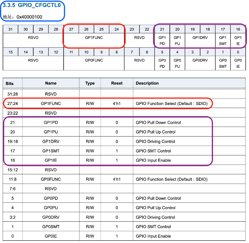
BL602 Configuration Register for Pins IO 0 and IO 1
Remember that we need to remap JTAG and PWM functions of the following pins…
| LED / JTAG Pin | BL602 Pin | Remap Pin Function |
|---|---|---|
JTAG TDI | IO 1 | SDIO → JTAG |
JTAG TCK | IO 2 | SDIO → JTAG |
JTAG TDO | IO 3 | SDIO → JTAG |
LED Blue | IO 11 | JTAG → PWM |
LED Green | IO 14 | JTAG → PWM |
LED Red | IO 17 | JTAG → PWM |
Here’s how we write the firmware code to remap the pins: sdk_app_helloworld/main.c
According to the pic above, we configure BL602 Pin IO 1 by writing to the memory address 0x40000100. We’ll call this address GP1FUNC_ADDR
//  GPIO_CFGCTL0
//  Address:0x40000100
uint32_t *GPIO_CFGCTL0 = (uint32_t *) 0x40000100;
uint32_t *GP1FUNC_ADDR = GPIO_CFGCTL0;
The pic above appears in the BL602 Reference Manual, Section 3.3.5 “GPIO_CFGCTL0”, Page 33.
(“地址” is Chinese for “Address”)
We’ll set bits 24 to 27 of GP1FUNC_ADDR to select the desired Pin Function (i.e. JTAG).
We define the Pin Function bit shift (offset) as GP1FUNC_SHIFT and the bit mask as GP1FUNC_MASK…
//  27:24 GP1FUNC
const uint32_t GP1FUNC_SHIFT = 24;
const uint32_t GP1FUNC_MASK  = 0x0f << GP1FUNC_SHIFT;
Then we’ll set bits 16 to 21 of GP1FUNC_ADDR for the GPIO Pin Control.
We define the Pin Control bit shift (offset) as GP1CTRL_SHIFT and the bit mask as GP1CTRL_MASK…
//  21:16 GP1CTRL
const uint32_t GP1CTRL_SHIFT = 16;
const uint32_t GP1CTRL_MASK  = 0x3f << GP1CTRL_SHIFT;
To map Pin IO 1 to JTAG, we set the Pin Function of GP1FUNC_ADDR to GPIO_FUN_JTAG, and the Pin Control to GPIO_CTRL
//  IO 1 becomes JTAG TDI. Also set the Pin Control.
*GP1FUNC_ADDR = (*GP1FUNC_ADDR & ~GP1FUNC_MASK & ~GP1CTRL_MASK)
    | (GPIO_FUN_JTAG << GP1FUNC_SHIFT)
    | (GPIO_CTRL     << GP1CTRL_SHIFT);
The Pin Function values (GPIO_FUN_JTAG and GPIO_FUN_PWM) are defined as…
//  Pin Functions (4 bits). From components/bl602/bl602_std/bl602_std/StdDriver/Inc/bl602_gpio.h
const uint32_t GPIO_FUN_PWM  =  8;  //  Pin Function for PWM  (0x8)
const uint32_t GPIO_FUN_JTAG = 14;  //  Pin Function for JTAG (0xe)
The Pin Control value GPIO_CTRL is defined as…
//  Pin Control (6 bits)
//  Pull Down Control: 0 (1 bit)
//  Pull Up Control:   0 (1 bit)
//  Driving Control:   0 (2 bits)
//  SMT Control:       1 (1 bit)
//  Input Enable:      1 (1 bit)
const uint32_t GPIO_CTRL = 3;  //  Pin Control
We apply the above steps to remap each Pin Function and set the Pin Control bits…
| LED / JTAG Pin | BL602 Pin | Remap Pin Function |
|---|---|---|
JTAG TDI | IO 1 | SDIO → JTAG |
JTAG TCK | IO 2 | SDIO → JTAG |
JTAG TDO | IO 3 | SDIO → JTAG |
LED Blue | IO 11 | JTAG → PWM |
LED Green | IO 14 | JTAG → PWM |
LED Red | IO 17 | JTAG → PWM |
The remapping code for all 6 pins may be found here: sdk_app_helloworld/main.c
Here are the values of the Pin Function and Pin Control registers before and after remapping…
| Register | Before | After | Pin |
|---|---|---|---|
GPIO_CFGCTL0 | bb 17 bb 17 | ee 03 bb 17 | 1 |
GPIO_CFGCTL1 | 11 03 bb 17 | ee 03 ee 03 | 2, 3 |
GPIO_CFGCTL5 | 0e 03 0b 03 | 08 03 0b 03 | 11 |
GPIO_CFGCTL7 | 0b 03 0e 03 | 0b 03 08 03 | 14 |
GPIO_CFGCTL8 | 0e 03 07 17 | 08 03 07 17 | 17 |
(Changed values have been highlighted)
Note that the Pin Function fields (4 bits each) have been changed to 0xe for JTAG and 0x8 for PWM.
The Pin Control fields (6 bits each) have also been changed to 0x03.
Let’s test the remapped JTAG Port on our PineCone!
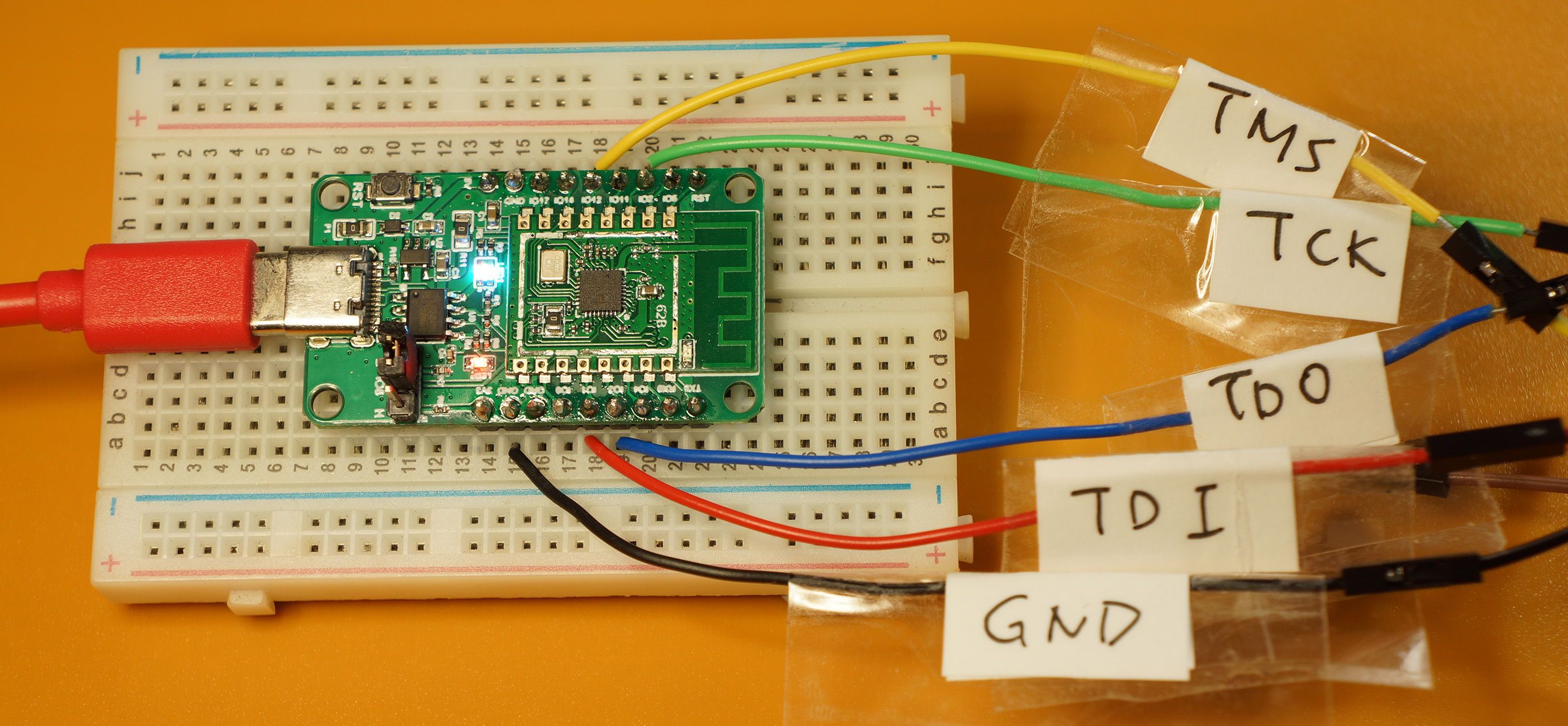
Remapped JTAG Port connected to JTAG Debugger. The LED lights up in bright white to signify that the JTAG Port has been remapped. Jumper is set to L, for Normal Mode.
How shall we test the JTAG Port remap?
We test by flashing a modified helloworld firmware that contains the remap code from the previous section…
Disconnect PineCone and JTAG Debugger from our computer
Connect the remapped JTAG Pins from PineCone to our JTAG Debugger…
| JTAG Debugger | PineCone Pin | Wire Colour |
|---|---|---|
TDI | IO 1 | Red |
TCK | IO 2 | Green |
TDO | IO 3 | Blue |
TMS | IO 12 | Yellow |
GND | GND | Black |
(See the pic above)
Set the PineCone Jumper to H (Bootloader Mode), because we shall be flashing the firmware shortly
Connect both PineCone and JTAG Debugger to our computer’s USB ports
The firmware code from the previous section has been built and uploaded as a GitHub Release. Here’s how we download the firmware the remaps the JTAG Port…
Browse to this GitHub Release…
Scroll to the bottom. Under Assets, click build_out.zip
Unzip the downloaded file build_out.zip
In the extracted files, look for…
build_out/sdk_app_helloworld.binWe shall be flashing sdk_app_helloworld.bin in the next step.
This version of the helloworld app has been modified to remap the JTAG Port.
Check that the PineCone Jumper has been set to H (Bootloader Mode), ready for flashing
Follow the instructions in this article to flash the sdk_app_helloworld.bin firmware that we have just downloaded. (Not the one from GitHub Actions)
“Quick Peek of PineCone BL602 RISC-V Evaluation Board”, Section 4.2: “Flashing Firmware”
When selecting the firmware file, remember to choose the sdk_app_helloworld.bin firmware that we have just downloaded.
Make sure there are no spaces in the firmware pathname.
After flashing the remap firmware, set the PineCone Jumper to L (Normal Mode) and power on PineCone. (Or press the Reset Button)
PineCone’s LED should light up bright white to signify that the JTAG Port has been remapped
Run OpenOCD using the same steps that we have covered in this article
We should see the same OpenOCD output, including the CPU ID.
This means that the remapped JTAG Port is working OK.
Remap Tip: When we reboot PineCone with Jumper set to H (Bootloader Mode), PineCone switches back to the Default JTAG Port. The LED turns multicolour.
Set the Jumper to L (Normal Mode) and reboot PineTime to restore the Remapped JTAG Port. The LED turns bright white.
To remove the remap firmware, follow the instructions in this article to flash the original sdk_app_helloworld.bin firmware from GitHub Actions. (Not the modified one we have just downloaded)
“Quick Peek of PineCone BL602 RISC-V Evaluation Board”, Section 4.2: “Flashing Firmware”
Set PineCone’s Jumper to L (Normal Mode) and power on PineCone.
The LED should no longer light up after booting
This signifies that the JTAG Port is no longer remapped. And we’re back to the default JTAG Port.
PineCone with Remapped JTAG Port. The LED lights up in bright white to signify that the JTAG Port has been remapped.
What are the options for resolving the conflict between the JTAG Pins and the LED Pins on PineCone?
We have a couple of options…
Connect the LED to other pins. Keep the default JTAG Port.
We’ll no longer have the multicolour lights during JTAG programming… But this option allows us to control the LED while doing debugging over JTAG, without having to remap the JTAG Port.
This makes PineCone coding easier. And we’ll never have to worry about connecting our JTAG Debugger to the wrong PineCone Pins.
This is my preferred option, though it will cost more to redesign and manufacture the board.
LED is connected on the default JTAG Pins.
But will we need to use the LED and JTAG Debugging at the same time?
Only LED: We’ll remap the LED Pins to PWM so that we may control them.
Only JTAG: We’ll use the default JTAG Port. No remapping needed.
(And we get free disco lights during JTAG loading and debugging)
Both LED and JTAG: This gets tricky.
As we have learnt earlier, we need to remap the LED Pins to PWM, and remap the JTAG Port to other pins.
This remapping can be done in the PineCone Firmware.
But whenever PineCone reboots, the JTAG Port reverts to the default pins, until our firmware remaps the port.
This may be a problem if we need to reboot PineCone during JTAG loading or debugging.
Alternatively: We may remap the LED and JTAG pins in the PineCone Bootloader blsp_boot2
This ensures that the pins are remapped quickly whenever PineCone reboots.
We hear that Sipeed’s upcoming BL602 Board will have an onboard JTAG Debugger. (Probably FT2232)
This increases the cost of the BL602 board… But it simplifies the USB connection between our computer and the BL602 board.
For PineCone we’re using 2 USB ports (PineCone USB + JTAG Debugger). With an integrated JTAG Debugger, we’ll need only 1 USB port.
Today we have connected OpenOCD to PineCone… Next we shall try loading and debugging RISC-V firmware on PineCone! (With VSCode, GDB, …)
In the above article we’ll also be testing the Embedded Rust Firmware, kindly contributed by the Sipeed BL602 Community.
Got a question, comment or suggestion? Create an Issue or submit a Pull Request here…