📝 12 Apr 2023
Quectel EG25-G LTE Modem inside PinePhone
What makes Pine64 PinePhone a phone? It’s the 4G LTE Modem inside that makes Phone Calls and sends Text Messages!
Now we’re building a Feature Phone with Apache NuttX RTOS (Real-Time Operating System). To make things simpler, we’re writing down everything we know about the 4G LTE Modem, and how it works inside PinePhone…
What’s the Quectel EG25-G LTE Modem
How it’s connected inside PinePhone
How we make Phone Calls and send Text Messages
How we power up the LTE Modem
Programming the LTE Modem with UART, USB and Apache NuttX RTOS
Read on to learn all about PinePhone’s 4G LTE Modem…
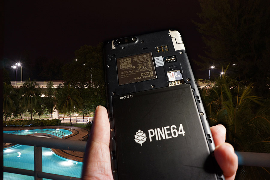
What’s this LTE Modem?
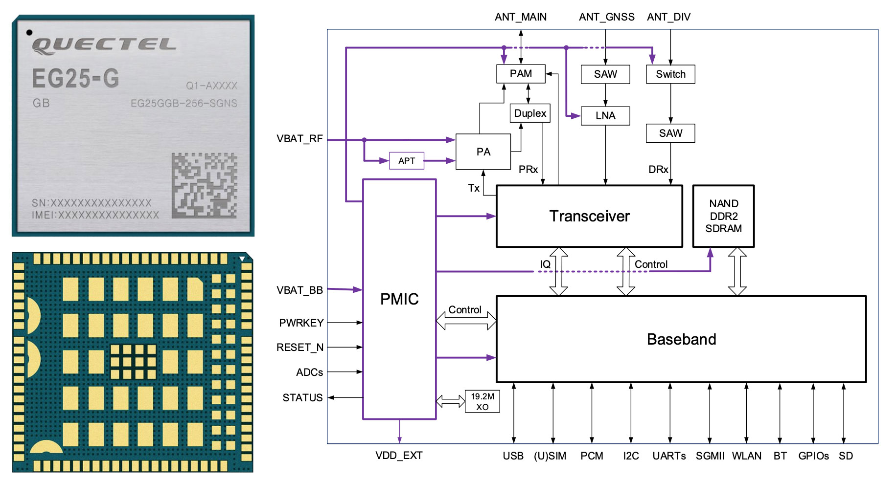
Inside PinePhone is the Quectel EG25-G LTE Modem for 4G LTE Voice Calls, SMS and Mobile Data, plus GPS (pic above)…
To control the LTE Modem, we send AT Commands…
So to dial the number 1711, we send this AT Command…
ATD1711;The LTE Modem has similar AT Commands for SMS and Mobile Data.
(EG25-G runs on Qualcomm MDM 9607 with a Cortex-A7 CPU inside)
How to send the AT Commands to LTE Modem?
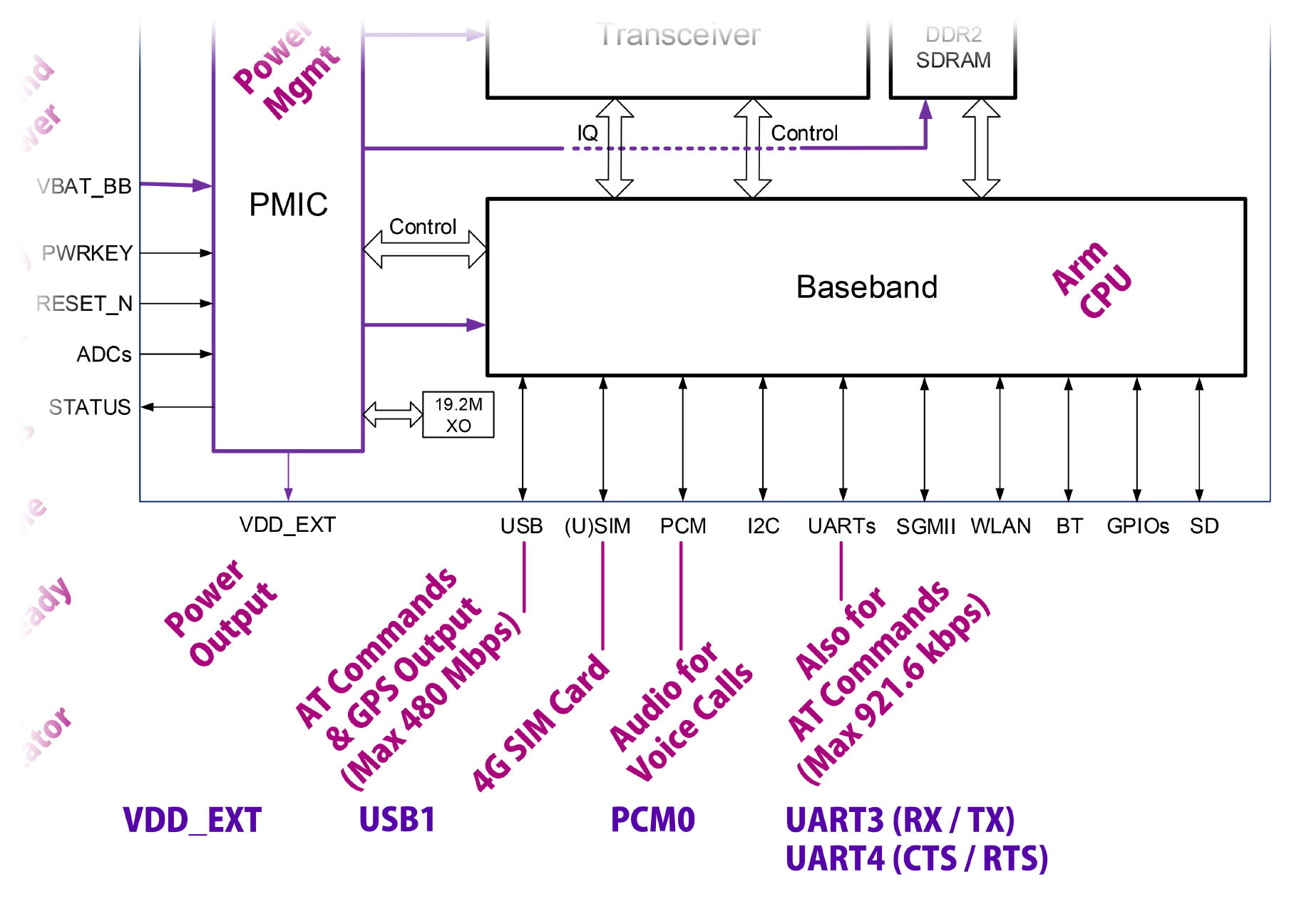
The LTE Modem accepts AT Commands in two ways (pic below)…
Via the UART Port (Serial)
Which is Slower: Up to 921.6 kbps
Via the USB Port (USB Serial)
Which is Faster: Up to 480 Mbps
So if we’re sending and receiving lots of 4G Mobile Data, USB is the better way.
(UART Interface is probably sufficient for a Feature Phone)
Let’s talk about the UART and USB Interfaces…
There’s a band of bass players in my PinePhone?
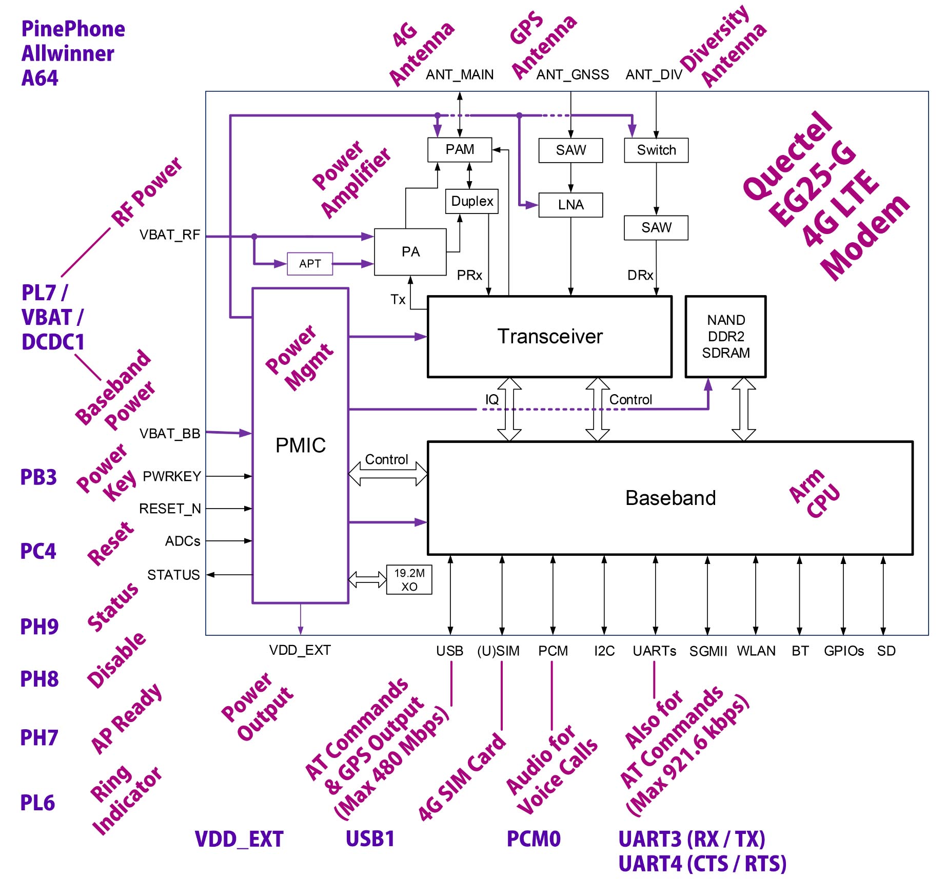
Ahem the Baseband Processor inside the LTE Modem (pic above) is the hardware that handles the Radio Functions for 4G LTE and GPS.
According to the PinePhone Schematic (Page 15), the Baseband Processor talks to PinePhone (Allwinner A64) over the following Data Interfaces (pic above)…
USB ⇆ A64 Port USB1 (USB Serial)
For AT Commands and GPS Output. (Up to 480 Mbps)
SIM ⇆ PinePhone 4G SIM Card
For connecting to the 4G LTE Mobile Network.
PCM ⇆ A64 Port PCM0
PCM Digital Audio Stream for 4G Voice Calls.
UART ⇆ A64 Port UART3 (RX / TX), UART4 (CTS / RTS), PB2 (DTR)
Simpler, alternative interface for AT Commands. Default 115.2 kbps, up to 921.6 kbps.
UART is slower than USB, so we should probably use USB instead of UART.
(Unless we’re building a simple Feature Phone without GPS)
PinePhone also controls the LTE Modem with a bunch of GPIO Pins…
PinePhone’s LTE Modem is controlled only by AT Commands?
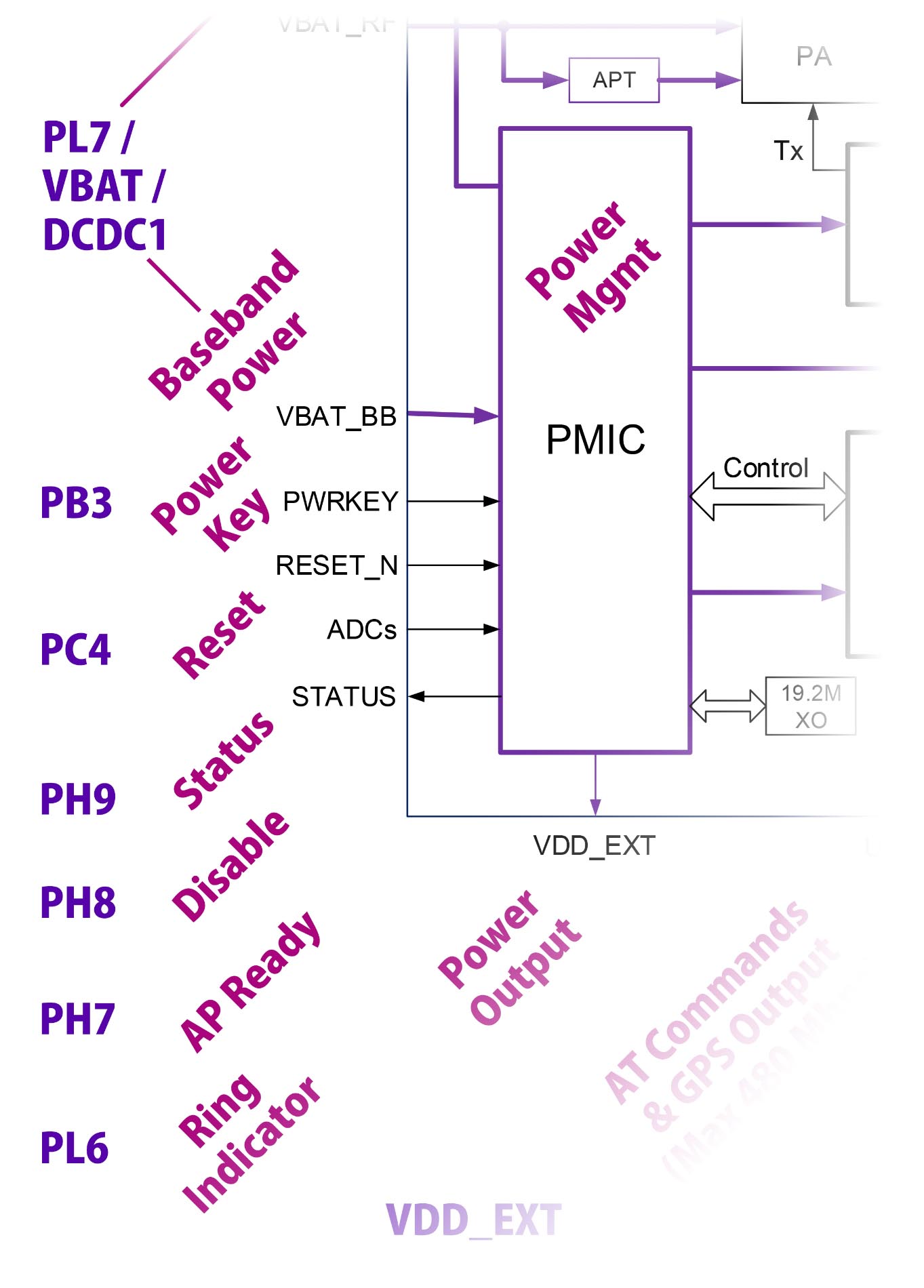
There’s more! According to the PinePhone Schematic (Page 15), the LTE Modem is controlled by the following GPIO Pins (pic above)…
Baseband Power ← A64 Port PL7
Supplies power to LTE Modem.
(Also connected to Battery Power VBAT and Power Management DCDC1)
Power Key ← A64 Port PB3
Power up the LTE Modem.
Reset ← A64 Port PC4
Reset the LTE Modem.
We’ll control the above GPIO Pins to power up the LTE Modem at startup. (More in the next section)
Also at startup, we’ll read this GPIO Pin to check if the LTE Modem is hunky dory…
Status → A64 Port PH9
Read the Modem Status.
These GPIO Pins control the Airplane Mode and Sleep State…
Disable ← A64 Port PH8
Enable or Disable Airplane Mode.
AP Ready ← A64 Port PH7
Set the Modem Sleep State.
And the LTE Modem signals PinePhone on this GPIO Pin for Incoming Calls and SMS Messages…
Ring Indicator → A64 Port PL6
Indicates Incoming Calls and SMS Messages.
Let’s power up the LTE Modem…
How will we power up the LTE Modem?
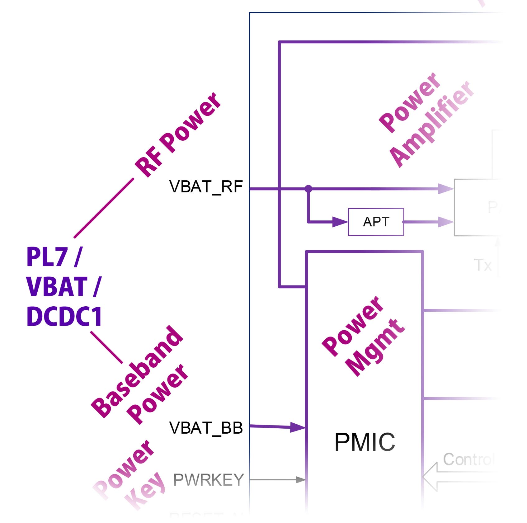
PinePhone Schematic (Page 15) says that PinePhone controls the power via GPIO Pin PL7 (pic above)…
RF Power ← A64 Port PL7
Supplies power to the Radio Frequency Transmitter and Receiver.
(4G LTE and GPS Transceiver)
Baseband Power ← A64 Port PL7
Supplies power to the Baseband Processor.
(4G LTE and GPS Radio Functions)
GPIO Pin PL7 (bottom left) switches on the Battery Power 4G-BAT (top left)…

Which powers the LTE Modem via VBAT_BB (top right).
Thus LTE Modem won’t power up without the Lithium-ion Battery.
(WPM1481 is a Power Controller)
What’s Switch SW1-A? (Bottom left)
Hardware Privacy Switch 1 (Modem) should be set to “On”.
Or the LTE Modem won’t power on!
(Indeed that’s a Hardware Switch, not a Soft Switch)
So we set GPIO Pin PL7 and the modem powers on?
There’s a Soft Switch inside the LTE Modem that we need to toggle…
Power Key ← A64 Port PB3
Power up the LTE Modem.
Sounds complicated, but we’ll explain the complete Power Up Sequence in a while.
(Power Key works like the press-and-hold Power Button on vintage Nokia Phones)
Anything else to power up the LTE Modem?
In a while we’ll set the Reset Pin and check the Status Pin…
Reset ← A64 Port PC4
Reset the LTE Modem.
Status → A64 Port PH9
Read the Modem Status.
We need to program PinePhone’s Power Management Integrated Circuit (PMIC) to supply 3.3 V on DCDC1. Here’s why…
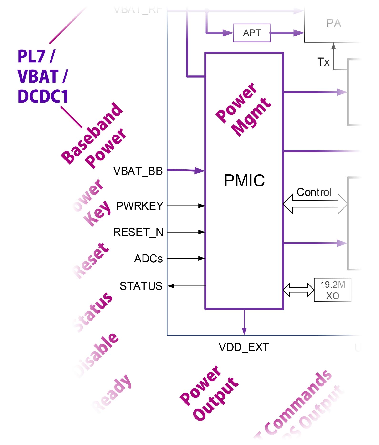
Wait there’s a Power Output for the LTE Modem?
Yeah it gets confusing. The LTE Modem outputs 1.8 Volts to PinePhone (pic above)…
Power Output (1.8 V) → PinePhone VDD_EXT
Power Output from LTE Modem to PinePhone. (1.8 V)
Which goes into PinePhone’s Voltage Translators as VDD_EXT (top left)…
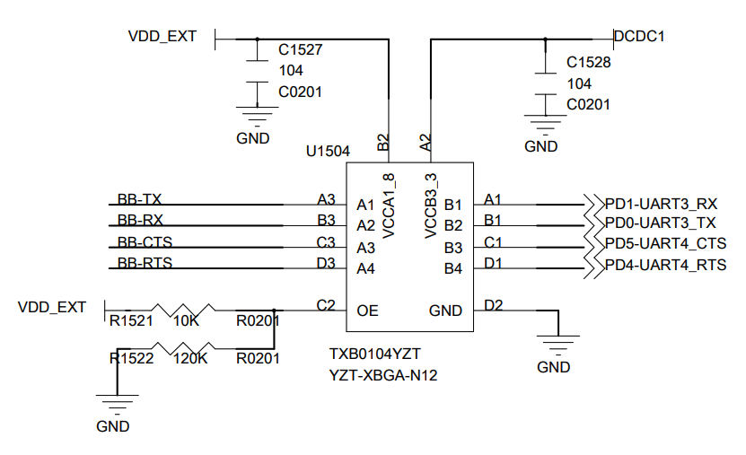
(TXB0104 is a Voltage Translator)
The circuit above converts the UART Signals (TX / RX / CTS / RTS)…
From 1.8 V (LTE Modem, left)
To 3.3 V (PinePhone, right)
Voltage Translators are also used for the LTE Modem Control Pins.
What’s DCDC1? (Top right)
We need to program PinePhone’s Power Management Integrated Circuit (PMIC) to supply 3.3 V on DCDC1.
Otherwise the UART Port (and the Control Pins) will get blocked by the Voltage Translators.
Why 1.8 V for the LTE Modem?
Most parts of the LTE Modem run on 3.3 V… Just that it needs to power up the SIM Card at 1.8 V. (See this)
(Remember that the SIM Card is actually a microcontroller)
This Low Voltage Signaling is probably meant for newer, power-efficient gadgets. (Like this)
Whoa LTE Modem has more pins than a Bowling Alley! (Pic above)
How exactly do we power up the LTE Modem?
Earlier we spoke about PinePhone’s GPIO Pins that control the LTE Modem…
| LTE Modem Pin | A64 GPIO Pin |
|---|---|
| RF Power | ← PL7 |
| Baseband Power | ← PL7 |
| Reset | ← PC4 |
| Power Key | ← PB3 |
| Disable | ← PH8 |
| Status | → PH9 |
This is how we control the GPIO Pins to power up the LTE Modem…
Program PinePhone’s Power Management Integrated Circuit (PMIC) to supply 3.3 V on DCDC1 (Like this)
We skip this because DCDC1 is already powered on.
Set PL7 to High to power on the RF Transceiver and Baseband Processor
Set PC4 to Low to deassert LTE Modem Reset
Set PH7 (AP-READY) to Low to wake up the modem
Set PB2 (DTR) to Low to wake up the modem
Wait 30 milliseconds for VBAT Power Supply to be stable
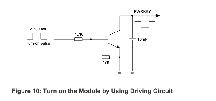
Toggle PB3 (Power Key) to start the LTE Modem, like this:
Set PB3 to High…
And wait 600 milliseconds…
Then set PB3 to Low.
Set PH8 to High to disable Airplane Mode
Read PH9 to check the LTE Modem Status:
PH9 goes from High to Low when the LTE Modem is ready, in 2.5 seconds.
UART and USB Interfaces will be operational in 13 seconds
EG25-G Hardware Design (Page 41) beautifully illustrates the Power On Sequence…
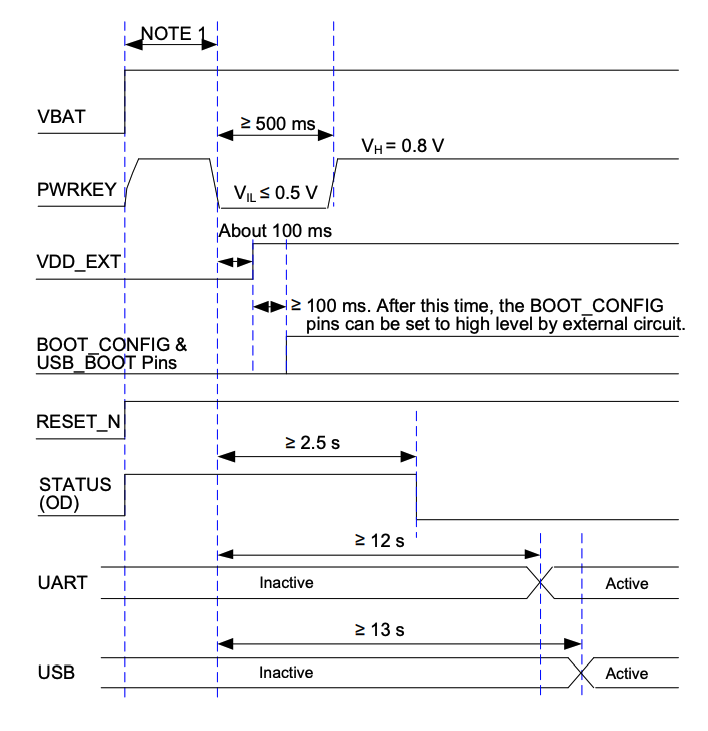
Note that Power Key and Reset are High-Low Inverted when accessed via GPIO Pins PC4 and PB3.
(High becomes Low and vice versa)
Power Key looks funky: High → Low → High…
Yeah the Power Key is probably inspired by the press-and-hold Power Button on vintage Nokia Phones.
(Power Key works differently on pre-production PinePhones)
Let’s implement the steps with Apache NuttX RTOS…
(Kudos to Genode OS for the Power On Sequence)
We’ve seen the Power On Sequence for LTE Modem…
How will we implement it in Apache NuttX RTOS?
This is how we implement the LTE Modem’s Power On Sequence in NuttX: pinephone_modem.c
// Read PH9 to check LTE Modem Status
#define STATUS (PIO_INPUT | PIO_PORT_PIOH | PIO_PIN9)
ret = a64_pio_config(STATUS);
DEBUGASSERT(ret == OK);
_info("Status=%d\n", a64_pio_read(STATUS));(a64_pio_config comes from A64 PIO Driver)
We begin by reading PH9 for the LTE Modem Status.
Then we set PL7 to High to power up the RF Transceiver and Baseband Processor: pinephone_modem.c
// Set PL7 to High to Power On LTE Modem (4G-PWR-BAT)
// Configure PWR_BAT (PL7) for Output
#define P_OUTPUT (PIO_OUTPUT | PIO_PULL_NONE | PIO_DRIVE_MEDLOW | \
                  PIO_INT_NONE | PIO_OUTPUT_SET)
#define PWR_BAT (P_OUTPUT | PIO_PORT_PIOL | PIO_PIN7)
a64_pio_config(PWR_BAT);  // TODO: Check result

// Set PWR_BAT (PL7) to High
a64_pio_write(PWR_BAT, true);
// Omitted: Print the status(a64_pio_write comes from A64 PIO Driver)
(pinephone_modem_init is called by pinephone_bringup)
We set PC4 to Low to deassert the LTE Modem Reset…
// Set PC4 to Low to Deassert LTE Modem Reset (BB-RESET / RESET_N)
// Configure RESET_N (PC4) for Output
#define RESET_N (P_OUTPUT | PIO_PORT_PIOC | PIO_PIN4)
a64_pio_config(RESET_N);  // TODO: Check result

// Set RESET_N (PC4) to Low
a64_pio_write(RESET_N, false);
// Omitted: Print the status
Set PH7 (AP-READY) and PB2 (DTR) to Low to wake up the modem…
// Set AP-READY (PH7) to Low to wake up modem
// Configure AP-READY (PH7) for Output and set to Low
#define AP_READY (P_OUTPUT | PIO_PORT_PIOH | PIO_PIN7)
a64_pio_config(AP_READY);  // TODO: Check result
a64_pio_write(AP_READY, false);

// Set DTR (PB2) to Low to wake up modem
// Configure DTR (PB2) for Output and set to Low
#define DTR (P_OUTPUT | PIO_PORT_PIOB | PIO_PIN2)
a64_pio_config(DTR);  // TODO: Check result
a64_pio_write(DTR, false);
Wait 30 milliseconds for the power to be stable…
// Wait 30 ms
up_mdelay(30);
Now we toggle PB3 for the Power Key: High → 600 milliseconds → Low…
// Set PB3 to Power On LTE Modem (BB-PWRKEY / PWRKEY).
// PWRKEY should be pulled down at least 500 ms, then pulled up.
// Configure PWRKEY (PB3) for Output
#define PWRKEY (P_OUTPUT | PIO_PORT_PIOB | PIO_PIN3)
a64_pio_config(PWRKEY);  // TODO: Check result

// Set PWRKEY (PB3) to High
a64_pio_write(PWRKEY, true);
// Omitted: Print the status

// Wait 600 ms for PWRKEY
up_mdelay(600);
// Omitted: Print the status

// Set PWRKEY (PB3) to Low
a64_pio_write(PWRKEY, false);
// Omitted: Print the status
Finally we set PH8 to High to disable Airplane Mode…
// Set PH8 to High to Disable Airplane Mode (BB-DISABLE / W_DISABLE#)
// Configure W_DISABLE (PH8) for Output
#define W_DISABLE (P_OUTPUT | PIO_PORT_PIOH | PIO_PIN8)
a64_pio_config(W_DISABLE);  // TODO: Check result

// Set W_DISABLE (PH8) to High
a64_pio_write(W_DISABLE, true);
// Omitted: Print the status
To wrap up, we wait for LTE Modem Status to turn Low: pinephone_modem.c
// Poll for Modem Status until it becomes Low
for (int i = 0; i < 30; i++) {  // Max 1 minute

  // Read the Modem Status
  uint32_t status = a64_pio_read(STATUS);
  // Omitted: Print the status

  // Stop if Modem Status is Low
  if (status == 0) { break; }

  // Wait 2 seconds
  up_mdelay(2000);
}
Let’s run this!
We’ve implemented the Power On Sequence for LTE Modem…
Does it work on Apache NuttX RTOS?
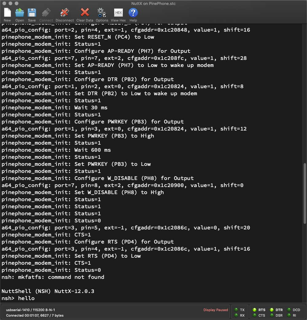
Yes it works! NuttX reads the Modem Status and switches on the power (PL7)…
Configure STATUS (PH9) for Input
Status=0

Set PWR_BAT (PL7) to High
Status=1Then it deasserts the reset (PC4) and wakes up the modem (PH7 and PB2)…
Set RESET_N (PC4) to Low
Set AP-READY (PH7) to Low to wake up modem
Set DTR (PB2) to Low to wake up modem

Wait 30 ms
Status=1
NuttX toggles the Power Key (PB3): High → 600 milliseconds → Low…
Set PWRKEY (PB3) to High
Wait 600 ms

Set PWRKEY (PB3) to Low
Status=1
And it disables Airplane Mode (PH8)…
Set W_DISABLE (PH8) to High
Status=1
Finally it waits for the LTE Modem Status (PH9) to turn Low…
pinephone_modem_init: Status=1
pinephone_modem_init: Status=1
pinephone_modem_init: Status=1
pinephone_modem_init: Status=0
And the LTE Modem is up! (Roughly 6 seconds)
This matches the Power Up Sequence that we saw earlier…
(EG25-G Hardware Design, Page 41)
(Power Key and Reset are High-Low Inverted)
Will the LTE Modem accept AT Commands now?
Not yet. The LTE Modem might take 30 seconds to be fully operational!
Let’s observe the UART Port…
(TXB0104 is a Voltage Translator)
LTE Modem has started successfully on NuttX…
How will we send AT Commands to the modem?
The LTE Modem is connected to PinePhone (Allwinner A64) at these UART Ports (pic above)…
A64 Port UART3: RX and TX
(GPIO PD1 and PD0)
(Default 115.2 kbps, up to 921.6 kbps)
A64 Port UART4: CTS and RTS
(GPIO PD5 and PD4)
A64 Port PB2: DTR
Thus we may check UART3 to see if the LTE Modem responds to AT Commands: hello_main.c
// Open /dev/ttyS1 (UART3)
int fd = open("/dev/ttyS1", O_RDWR);
printf("Open /dev/ttyS1: fd=%d\n", fd);
assert(fd > 0);

// Repeat 5 times: Write command and read response
for (int i = 0; i < 5; i++) {

  // Write command
  const char cmd[] = "AT\r";
  ssize_t nbytes = write(fd, cmd, strlen(cmd));
  printf("Write command: nbytes=%ld\n%s\n", nbytes, cmd);
  assert(nbytes == strlen(cmd));

  // Read response
  static char buf[1024];
  nbytes = read(fd, buf, sizeof(buf) - 1);
  if (nbytes >= 0) { buf[nbytes] = 0; }
  else { buf[0] = 0; }
  printf("Response: nbytes=%ld\n%s\n", nbytes, buf);

  // Wait a while
  sleep(2);
}

// Close the device
close(fd);
The NuttX App above sends the command “AT” to the LTE Modem over UART3. (5 times)
Watch what happens when we run it…
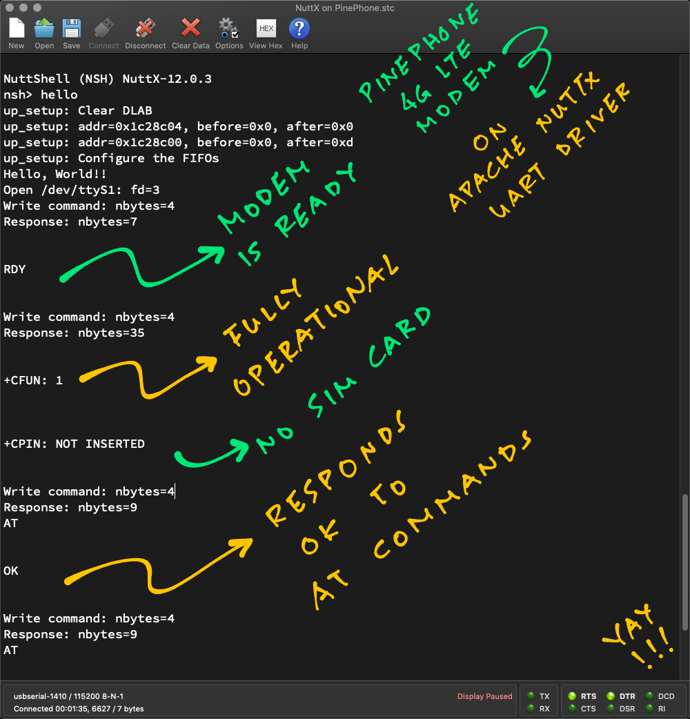
Our NuttX App sends command “AT” to the LTE Modem over UART3…
Open /dev/ttyS1
Write command: AT\r
But it hangs there. No response!
Remember that the LTE Modem might take 30 seconds to become operational. Be patient, the response appears in a while…
Response:
RDY“RDY” means that the LTE Modem is ready for AT Commands!
(EG25-G AT Commands, Page 297)
Our NuttX App sends command “AT” again…
Write command: AT\r
Response:
+CFUN: 1
+CPIN: NOT INSERTED
LTE Modem replies…
“+CFUN: 1”
This says that the LTE Modem is fully operational
“+CPIN: NOT INSERTED”
This says that we haven’t inserted a SIM Card into the LTE Modem
Our NuttX App sends command “AT” once more…
Write command: AT\r
Response:
AT
OK
LTE Modem echoes our command “AT”…
And responds to our command with “OK”.
Which means that our LTE Modem is running AT Commands all OK!
UART3 works with NuttX?
We modified the Allwinner A64 UART Driver to support UART3. The changes will be upstreamed to NuttX Mainline later…
TODO: Disable UART2 and /dev/ttyS2 so that UART3 maps neatly to /dev/ttyS3. (See this)
There’s another way to test the LTE Modem: Via USB…
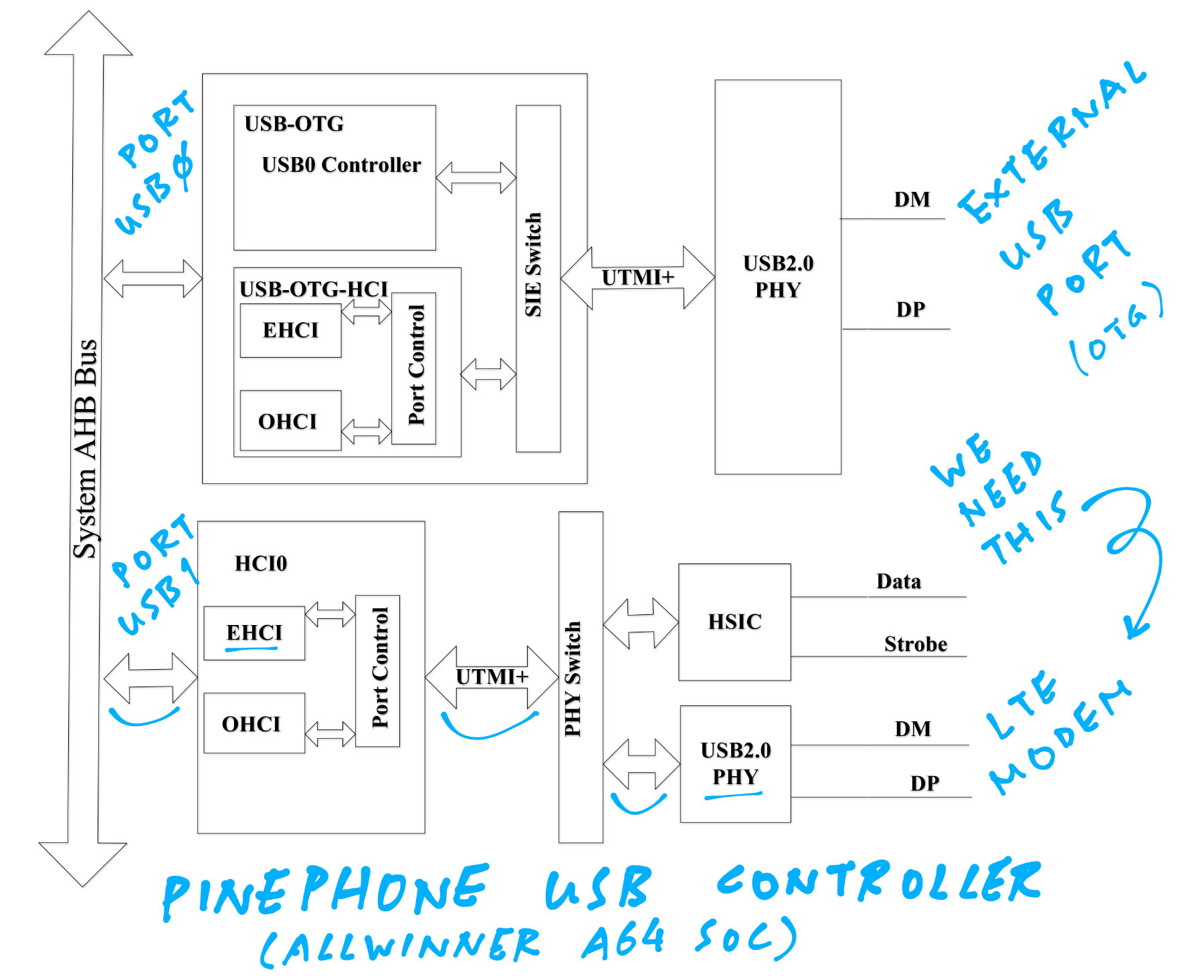
USB Controller Block Diagram from Allwinner A64 User Manual
We talked about testing the LTE Modem the UART way…
What about the USB way?
Yep the USB Interface should work for testing the LTE Modem…
USB ⇆ A64 Port USB1 (USB Serial)
(Up to 480 Mbps)
How’s that coming along?
We fixed the NuttX USB EHCI Driver (pic above) to handle USB Interrupts…
But somehow the LTE Modem isn’t triggering any USB Interrupts (13 seconds after startup)…
Which fails the enumeration of USB Devices (like the LTE Modem). And we can’t connect to the USB Interface of the LTE Modem.
But then we discovered that the GPIO Pins for Power Key and Reset are High-Low Inverted. So we need to retest.
Stay tuned for updates on the USB Testing!
(This crash needs to be fixed when USB Hub Support is enabled)
Quectel EG25-G LTE Modem inside PinePhone
I hope this article was helpful for learning about PinePhone’s 4G LTE Modem…
What’s the Quectel EG25-G LTE Modem
How it’s connected inside PinePhone
How we make Phone Calls and send Text Messages
How we power up the LTE Modem
Programming the LTE Modem with UART, USB and Apache NuttX RTOS
Up Next: Find out how we make phone calls and send text messages with PinePhone’s 4G LTE Modem…
Also check out the other articles on NuttX for PinePhone…
Many Thanks to my GitHub Sponsors for supporting my work! This article wouldn’t have been possible without your support.
Got a question, comment or suggestion? Create an Issue or submit a Pull Request here…
There’s plenty more inside PinePhone’s LTE Modem. Check out these articles…
Take note of these Limitations and Design Decisions…
LTE Modem Pinout is different for pre-production editions of PinePhone! (Like Braveheart 1.1)
I’m using PinePhone Hardware Revision 1.2 (Ubports Edition)…
Why are we experimenting with BOTH UART and USB for the LTE Modem?
What’s the purpose of the above LTE Modem pins?
This section describes the purpose of every LTE Modem pin connected to PinePhone…
From EG25-G Hardware Design (Page 22)…
| Pin Name | Pin No. | I/O | Description |
|---|---|---|---|
| VDD_EXT | 7 | PO | Provide 1.8 V for external circuit |
From EG25-G Hardware Design (Page 22)…
| Pin Name | Pin No. | I/O | Description |
|---|---|---|---|
| PWRKEY | 21 | DI | Turn on / off the module |
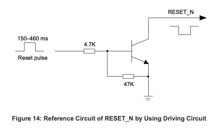
| RESET_N | 20 | DI | Reset signal of the module |
PWRKEY should be pulled down at least 500 ms, then pulled up
“Make sure that VBAT is stable before pulling down PWRKEY pin. It is recommended that the time between powering up VBAT and pulling down PWRKEY pin is no less than 30 ms.”
“RESET_N pin can be used to reset the module. The module can be reset by driving RESET_N to a low level voltage for 150–460 ms”
Note: PWRKEY and RESET_N are High-Low Inverted when accessed through PinePhone’s GPIO Pins
(High becomes Low and vice versa)
From EG25-G Hardware Design (Page 22)…
| Pin Name | Pin No. | I/O | Description |
|---|---|---|---|
| STATUS | 61 | OD | Indicate the module operating status |
When PWRKEY is pulled Low, STATUS goes High for ≥2.5 s, then STATUS goes Low
From EG25-G Hardware Design (Page 22)…
| Pin Name | Pin No. | I/O | Description |
|---|---|---|---|
| USB_VBUS | 71 | PI | USB connection detection |
From EG25-G Hardware Design (Page 24)…
| Pin Name | Pin No. | I/O | Description |
|---|---|---|---|
| RI | 62 | DO | Ring indicator |
| CTS | 64 | DO | Clear to send |
| RTS | 65 | DI | Request to send |
| DTR | 66 | DI | Data terminal ready, sleep mode control |
| TXD | 67 | DO | Transmit data |
| RXD | 68 | DI | Receive data |
Voltage Level is 1.8 V
Ring Indicator is configured with AT Command “AT+QCFG” (See this)
CTS and RTS might not work correctly on PinePhone (See this)
DTR is pulled up by default. Low level wakes up the module.
TXD and RXD (UART) default to 115.2 kbps, support up to 921.6 kbps
From EG25-G Hardware Design (Page 32)…
| Pin Name | Pin No. | I/O | Description |
|---|---|---|---|
| W_DISABLE# | 4 | DI | Airplane mode control |
| AP_READY | 2 | DI | Application processor sleep state detection |
Voltage Level is 1.8 V
“W_DISABLE# pin is pulled up by default. Driving it to low level will let the module enter airplane mode”
From EG25-G Hardware Design (Page 21)…
| Type | Description |
|---|---|
| AI | Analog Input |
| AO | Analog Output |
| DI | Digital Input |
| DO | Digital Output |
| IO | Bidirectional |
| OD | Open Drain |
| PI | Power Input |
| PO | Power Output |