📝 24 Mar 2023
USB Controller Block Diagram from Allwinner A64 User Manual
Weeks ago we talked about porting Apache NuttX RTOS (Real-Time Operating System) to Pine64 PinePhone. And how we might turn it into a Feature Phone…
But to make phone calls and send text messages, we need to control the LTE Modem over USB…
Thus today we’ll build a USB Driver for NuttX on PinePhone. As we find out…
What’s USB Enhanced Host Controller Interface (EHCI)
Why it’s simpler than USB On-The-Go (OTG)
How we ported the USB EHCI Driver from NuttX to PinePhone
Handling USB Clocks and USB Resets on PinePhone
(Based on tips from U-Boot Bootloader)
And the NuttX EHCI Driver boots OK on PinePhone! 🎉
Let’s dive into the fascinating world of USB EHCI…
(Thanks to Lwazi Dube for teaching me about EHCI 🙂)
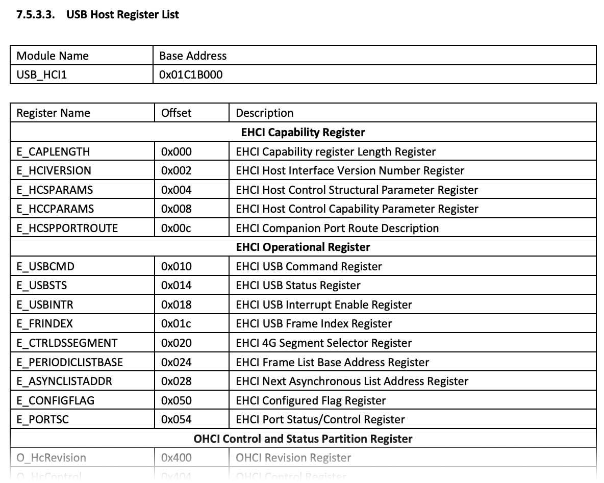
USB EHCI Registers in Allwinner A64 User Manual (Page 585)
What’s USB EHCI?
According to the Official Spec…
“The Enhanced Host Controller Interface (EHCI) specification describes the Register-Level Interface for a Host Controller for the Universal Serial Bus (USB) Revision 2.0”
“The specification includes a description of the Hardware and Software Interface between System Software and the Host Controller Hardware”
So EHCI is a standard, unified way to program the USB Controller on any Hardware Platform?
Yep and USB EHCI is supported on PinePhone!
Which means we can build the USB Driver for PinePhone… By simply reading and writing the (Memory-Mapped) EHCI Registers in Allwinner A64 USB Controller! (Pic above)
What are the USB EHCI Registers?
The Standard EHCI Registers are documented here…
“Enhanced Host Controller Interface for USB 2.0: Specification”
(Skip the “Version 1.1 Addendum”, Allwinner A64 only implements Version 1.0 of the spec)
Allwinner A64 implements the EHCI Registers for Port USB1 at…
USB_HCI1 Base Address: 0x01C1 B000
(Pic above)
More about this in the Allwinner A64 User Manual…
Section 7.5.3.3: USB Host Register List (Page 585, pic above)
Section 7.5.3.4: EHCI Register Description (Page 587)
Section 7.5.3.5: OHCI Register Description (Page 601)
Section 7.5.3.6: HCI Interface Control and Status Register Description (Page 619)
Section 7.5.3.7: USB Host Clock Requirement (Page 620)
This looks messy, but the NuttX EHCI Driver will probably run OK on PinePhone.
USB EHCI sounds like a lifesaver?
Yep USB Programming on PinePhone would be super complicated without EHCI!
Let’s take a peek at life without EHCI…
(EHCI always reminds me of Don Norman)
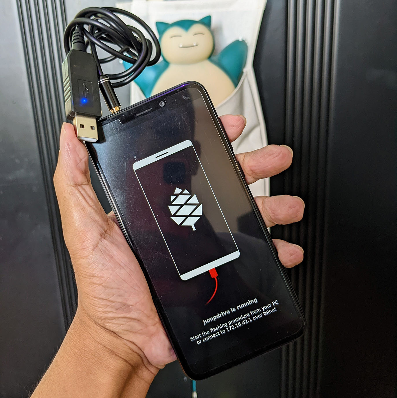
PinePhone Jumpdrive appears as a USB Drive when connected to a computer
What’s USB On-The-Go?
PinePhone supports USB On-The-Go (OTG), which works as two modes…
USB Host: PinePhone controls other USB Devices
USB Device: PinePhone is controlled by a USB Host
This means if we connect PinePhone to a computer, it will appear as a USB Drive.
(Assuming the right drivers are started)
Is USB OTG compatible with USB EHCI?
EHCI supports only USB Host, not USB Device.
(Hence the name “Enhanced Host Controller Interface”)
PinePhone supports both USB OTG and USB EHCI. PinePhone’s USB Physical Layer can switch between OTG and EHCI modes. (As we’ll soon see)
How would we program USB OTG?
To do USB OTG, we would need to create a driver for the Mentor Graphics (MUSB) OTG Controller inside PinePhone…
Which gets really low-level and complex. (Like this)
Thankfully we won’t need USB OTG and the Mentor Graphics Driver. Here’s why…
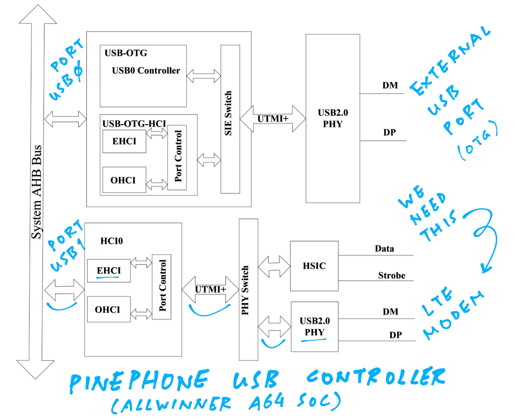
USB Controller Block Diagram from Allwinner A64 User Manual (Page 583)
Phew! We’re doing USB EHCI, not USB OTG?
According to the Allwinner A64 User Manual (Page 583), there are two USB Ports in Allwinner A64: USB0 and USB1…
Port USB0 is exposed as the External USB Port on PinePhone
(Top part of pic above)
Port USB1 is connected to the Internal LTE Modem
(Bottom part of pic above)
The names are kinda confusing in the A64 User Manual…
| USB Port | Alternate Name | Base Address |
|---|---|---|
| Port USB0 | USB-OTG-EHCI / OHCI | 0x01C1 A000 (USB_HCI0) |
| Port USB1 | USB-EHCI0 / OHCI0 | 0x01C1 B000 (USB_HCI1) |
Port USB0 isn’t documented, but it appears in the Memory Mapping of Allwinner A64 User Manual. (Page 73)
But they look so different in the pic…
They ain’t two peas in a pod of pink dolphins because…
Only Port USB0 supports USB On-The-Go (OTG).
Which means if we connect PinePhone to a computer, it will appear as a USB Drive. (Assuming the right drivers are started)
That’s why Port USB0 is exposed as the External USB Port on PinePhone.
Both USB0 and USB1 support USB Enhanced Host Controller Interface (EHCI).
Which will work only as a USB Host. (Not USB Device)
And that’s perfectly hunky dory for the LTE Modem on USB1. (Pic below)
We need the LTE Modem for our Feature Phone?
Exactly! Today we’re making a Feature Phone with the LTE Modem.
So we’ll talk only about Port USB1 (EHCI / Non-OTG), since it’s connected to the LTE Modem. (Pic below)
Let’s build the EHCI Driver…
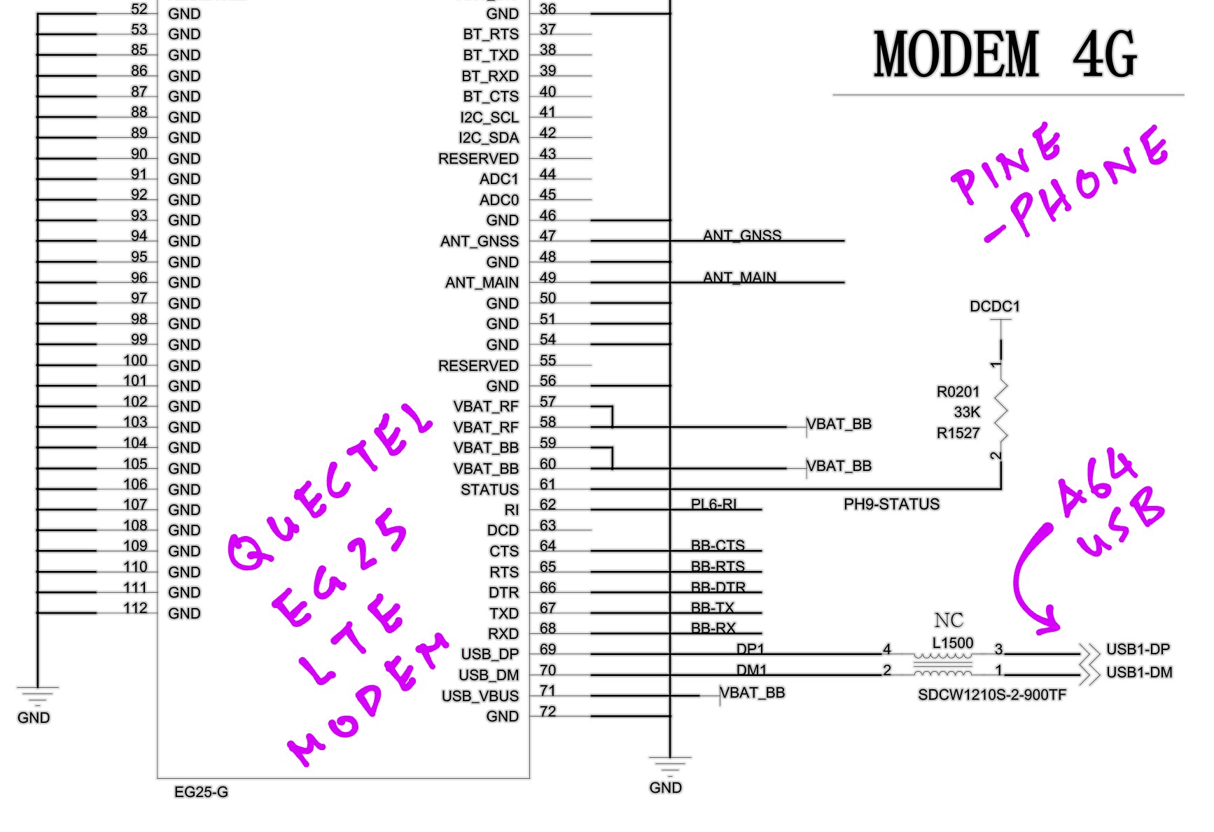
Quectel EG25-G LTE Modem in PinePhone Schematic (Page 15)
Does NuttX have a USB EHCI Driver?
Yep! Apache NuttX RTOS has a USB EHCI Driver…
Which we’ll port to PinePhone as…
But the EHCI Register Addresses are specific to PinePhone right?
That’s why we customised the EHCI Register Addresses specially for PinePhone and Allwinner A64: a64_usbotg.h
// Address of EHCI Device / Host Capability Registers
// For Allwinner A64: USB_HCI1
#define A64_USBOTG_HCCR_BASE 0x01c1b000

// Address of Device / Host / OTG Operational Registers
// For Allwinner A64: USB_HCI1 + 0x10
#define A64_USBOTG_HCOR_BASE (A64_USBOTG_HCCR_BASE + 0x10)
(EHCI Base Address is 0x01C1 B000)
We start the USB EHCI Driver in the PinePhone Bringup Function: pinephone_bringup.c
int pinephone_bringup(void) {
  ...
  // Start the USB EHCI Driver
ret = a64_usbhost_initialize();(a64_usbhost_initialize is defined here)
(Which calls a64_ehci_initialize)
Let’s boot our new EHCI Driver on PinePhone and watch what happens…
What happens when we boot NuttX with our customised EHCI Driver?
When NuttX boots our EHCI Driver for PinePhone, it halts with an Assertion Failure…
Assertion failed:
at file: chip/a64_ehci.c:4996
task: nsh_main 0x4008b0d0
Which says that the a64_qh_s struct must be aligned to 32 bytes: a64_ehci.c
DEBUGASSERT((sizeof(struct a64_qh_s) & 0x1f) == 0);But somehow it’s not! The actual size of the a64_qh_s struct is 72 bytes…
sizeof(struct a64_qh_s) = 72Which most certainly isn’t aligned to 32 bytes.
Huh? What’s with the struct size?
Take a guess! Here’s the definition of a64_qh_s: a64_ehci.c
// Internal representation of the EHCI Queue Head (QH)
struct a64_qh_s {

  // Hardware representation of the queue (head)
  struct ehci_qh_s hw;

  // Endpoint used for the transfer
  struct a64_epinfo_s *epinfo;

  // First qTD in the list (physical address)
  uint32_t fqp;

  // Padding to assure 32-byte alignment
  uint8_t pad[8];
};
The pointer looks sus…
Yep epinfo is a pointer, normally 4 bytes on 32-bit platforms…
  // Pointer Size is Platform Dependent
  struct a64_epinfo_s *epinfo;
But PinePhone is the very first Arm64 port of NuttX!
Thus epinfo actually occupies 8 bytes on PinePhone and other 64-bit platforms.
How has the struct changed for 32-bit platforms vs 64-bit platforms?
On 32-bit platforms: a64_qh_s was previously 64 bytes
(48 + 4 + 4 + 8)
On 64-bit platforms: a64_qh_s is now 72 bytes
(48 + 8 + 4 + 8, round up for 4-byte alignment)
We fix this by padding a64_qh_s from 72 bytes to 96 bytes…
struct a64_qh_s {
  ...
  // Original Padding: 8 bytes
  uint8_t pad[8];

  // Added this: Pad from 72 to 96 bytes for 64-bit platforms
  uint8_t pad2[96 - 72];
};And this fixes our Assertion Failure!
This 64-bit patching sounds scary… What about other structs?
To be safe, we verified that the other Struct Sizes are still valid for 64-bit platforms: a64_ehci.c
DEBUGASSERT(sizeof(struct ehci_itd_s)  == SIZEOF_EHCI_ITD_S);
DEBUGASSERT(sizeof(struct ehci_sitd_s) == SIZEOF_EHCI_SITD_S);
DEBUGASSERT(sizeof(struct ehci_qtd_s)  == SIZEOF_EHCI_QTD_S);
DEBUGASSERT(sizeof(struct ehci_overlay_s) == 32);
DEBUGASSERT(sizeof(struct ehci_qh_s)   == 48);
DEBUGASSERT(sizeof(struct ehci_fstn_s) == SIZEOF_EHCI_FSTN_S);
FYI: These are the Struct Sizes in the EHCI Driver…
sizeof(struct a64_qh_s)    = 72
sizeof(struct a64_qtd_s)   = 32
sizeof(struct ehci_itd_s)  = 64
sizeof(struct ehci_sitd_s) = 28
sizeof(struct ehci_qtd_s)  = 32
sizeof(struct ehci_overlay_s) = 32
sizeof(struct ehci_qh_s)   = 48
sizeof(struct ehci_fstn_s) = 8
Let’s continue booting NuttX…
(We need to fix this NuttX typo: SIZEOF_EHCI_OVERLAY is defined twice)
So NuttX boots without an Assertion Failure?
Yeah but our USB EHCI Driver fails with a timeout when booting on PinePhone…
usbhost_registerclass:
  Registering class:0x40124838 nids:2
EHCI Initializing EHCI Stack
a64_printreg:
  01c1b010<-00000000
a64_printreg:
  01c1b014->00000000
EHCI ERROR:
  Timed out waiting for HCHalted.
  USBSTS: 000000
EHCI ERROR:
  a64_reset failed: 110
a64_usbhost_initialize:
ERROR: a64_ehci_initialize failedThe timeout happens while waiting for the USB Controller to Halt: a64_ehci.c
// Reset the USB EHCI Controller
static int a64_reset(void) {

  // Halt the EHCI Controller
  a64_putreg(0, &HCOR->usbcmd);

  // Wait for EHCI Controller to halt
  timeout = 0;
  do {
    // Wait one microsecond and update the timeout counter
    up_udelay(1);  timeout++;

    // Get the current value of the USBSTS register
    regval = a64_getreg(&HCOR->usbsts);
  }
  while (((regval & EHCI_USBSTS_HALTED) == 0) && (timeout < 1000));

  // Is the EHCI still running?  Did we timeout?
  if ((regval & EHCI_USBSTS_HALTED) == 0) {

    // Here's the Halt Timeout that we hit
    usbhost_trace1(EHCI_TRACE1_HCHALTED_TIMEOUT, regval);
    return -ETIMEDOUT;
  }
What’s a64_putreg and a64_getreg?
Our EHCI Driver calls a64_getreg and a64_putreg to read and write the EHCI Registers.
They appear in our log like so…
a64_printreg:
  01c1b010<-00000000

a64_printreg:
01c1b014->00000000Which means that our driver has written 0 to 01C1 B010, and read 0 from 01C1 B014.
What are 01C1 B010 and 01C1 B014?
01C1 B000 is the Base Address of the USB EHCI Controller on Allwinner A64
01C1 B010 is the USB Command Register USBCMD
01C1 B014 is the USB Status Register USBSTS
When we see this…
a64_printreg:
  01c1b010<-00000000

a64_printreg:
01c1b014->00000000It means…
Our driver wrote Command 0 (Stop) to USB Command Register USBCMD.
Which should Halt the USB Controller.
Then we read USB Status Register USBSTS.
This returns 0, which means that the USB Controller has NOT been Halted.
(HCHalted = 0)
That’s why the USB Driver failed: It couldn’t Halt the USB Controller at startup.
Why?
Probably because we haven’t powered on the USB Controller? Says our log…
TODO: Switch off USB bus power
TODO: Setup pins, with power initially off
TODO: Reset the controller from the OTG peripheral
TODO: Program the controller to be the USB host controllerAnd maybe we need to initialise the USB Physical Layer.
How do we power on the USB Controller?
Let’s get inspired by consulting the U-Boot Bootloader…
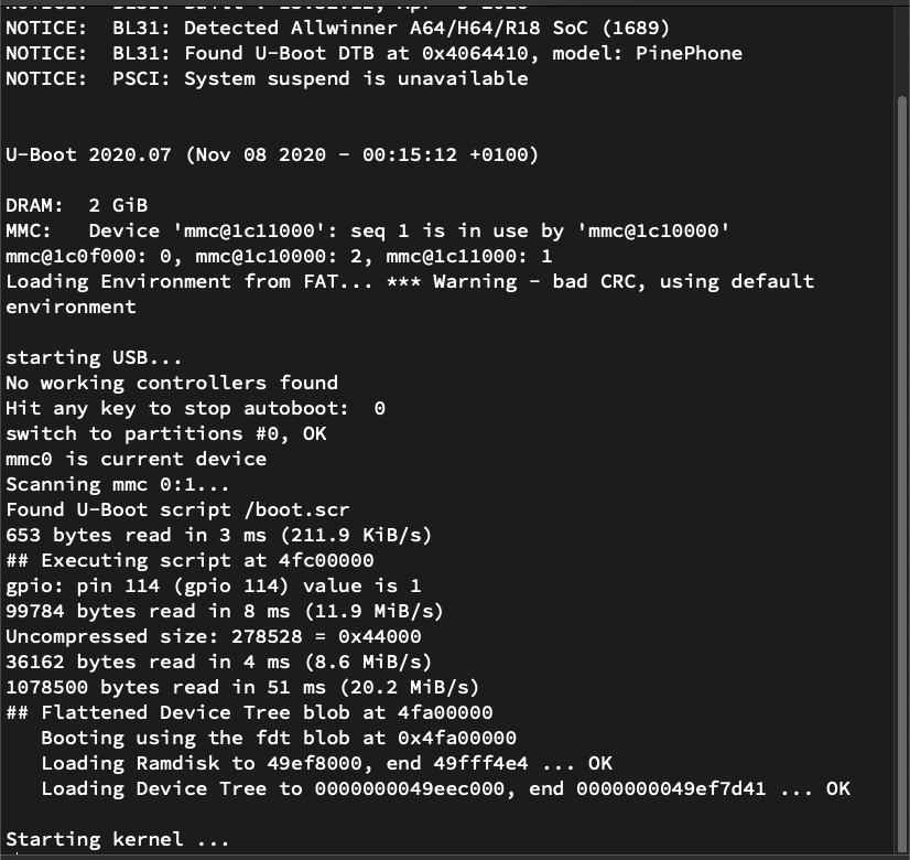
U-Boot Bootloader on PinePhone
We need to power on PinePhone’s USB Controller…
How can U-Boot Bootloader help?
U-Boot Bootloader is the very first thing that runs when we power on our PinePhone.
U-Boot allows booting from a USB Drive… Thus it must have a USB Driver inside!
Let’s find the PinePhone USB Driver inside U-Boot and study it.
How to find the PinePhone USB Driver in U-Boot?
When we search for PinePhone in the Source Code of U-Boot Bootloader, we find this Build Configuration: pinephone_defconfig
CONFIG_DEFAULT_DEVICE_TREE="sun50i-a64-pinephone-1.2"Which refers to this PinePhone Device Tree: sun50i-a64-pinephone-1.2.dts
#include "sun50i-a64-pinephone.dtsi"Which includes another Device Tree: sun50i-a64-pinephone.dtsi
#include "sun50i-a64.dtsi"
#include "sun50i-a64-cpu-opp.dtsi"
...
&ehci0 { status = "okay"; };
&ehci1 { status = "okay"; };

&usb_otg {
  dr_mode = "peripheral";
  status = "okay";
};

&usb_power_supply { status = "okay"; };
&usbphy { status = "okay"; };
Which includes this Allwinner A64 Device Tree: sun50i-a64.dtsi
usb_otg: usb@1c19000 {
  compatible = "allwinner,sun8i-a33-musb";
  reg = <0x01c19000 0x0400>;
  clocks = <&ccu CLK_BUS_OTG>;
  resets = <&ccu RST_BUS_OTG>;
  interrupts = <GIC_SPI 71 IRQ_TYPE_LEVEL_HIGH>;
  interrupt-names = "mc";
  phys = <&usbphy 0>;
  phy-names = "usb";
  extcon = <&usbphy 0>;
  dr_mode = "otg";
  status = "disabled";
};
That’s for USB OTG (On-The-Go), which we’ll skip today.
Next comes the USB PHY (Physical Layer), which is the electrical wiring for Ports USB0 and USB1: sun50i-a64.dtsi
usbphy: phy@1c19400 {
  compatible = "allwinner,sun50i-a64-usb-phy";
  reg =
    <0x01c19400 0x14>,
    <0x01c1a800 0x4>,
    <0x01c1b800 0x4>;
  reg-names =
    "phy_ctrl",
    "pmu0",
    "pmu1";
  clocks =
    <&ccu CLK_USB_PHY0>,
    <&ccu CLK_USB_PHY1>;
  clock-names =
    "usb0_phy",
    "usb1_phy";
  resets =
    <&ccu RST_USB_PHY0>,
    <&ccu RST_USB_PHY1>;
  reset-names =
    "usb0_reset",
    "usb1_reset";
  status = "disabled";
  #phy-cells = <1>;
};
(We’ll come back to clocks and resets in a while)
Then comes the EHCI Controller for Port USB0 (which we’ll skip): sun50i-a64.dtsi
ehci0: usb@1c1a000 {
  compatible = "allwinner,sun50i-a64-ehci", "generic-ehci";
  reg = <0x01c1a000 0x100>;
  interrupts = <GIC_SPI 72 IRQ_TYPE_LEVEL_HIGH>;
  clocks =
    <&ccu CLK_BUS_OHCI0>,
    <&ccu CLK_BUS_EHCI0>,
    <&ccu CLK_USB_OHCI0>;
  resets =
    <&ccu RST_BUS_OHCI0>,
    <&ccu RST_BUS_EHCI0>;
  phys = <&usbphy 0>;
  phy-names = "usb";
  status = "disabled";
};
Finally the EHCI Controller for Port USB1 (which we need): sun50i-a64.dtsi
ehci1: usb@1c1b000 {
  compatible = "allwinner,sun50i-a64-ehci", "generic-ehci";
  reg = <0x01c1b000 0x100>;
  interrupts = <GIC_SPI 74 IRQ_TYPE_LEVEL_HIGH>;
  clocks =
    <&ccu CLK_BUS_OHCI1>,
    <&ccu CLK_BUS_EHCI1>,
    <&ccu CLK_USB_OHCI1>;
  resets =
    <&ccu RST_BUS_OHCI1>,
    <&ccu RST_BUS_EHCI1>;
  phys = <&usbphy 1>;
  phy-names = "usb";
  status = "disabled";
};
How helpful is all this?
Super helpful! The above Device Tree says that the PinePhone USB Drivers we seek in U-Boot Bootloader are…
USB PHY (Physical Layer): “allwinner,sun50i-a64-usb-phy”
USB EHCI (Enhanced Host Controller Interface): “allwinner,sun50i-a64-ehci”, “generic-ehci”
USB OTG (On-The-Go): “allwinner,sun8i-a33-musb”
Let’s look inside the PinePhone USB Drivers for U-Boot…
What’s inside the PinePhone USB Drivers for U-Boot Bootloader?
Earlier we searched for the PinePhone USB Drivers inside U-Boot Bootloader and we found these…
Driver for USB PHY (Physical Layer):
Driver for USB EHCI (Enhanced Host Controller Interface):
We skip the USB OTG Driver because we’re only interested in the EHCI Driver (Non-OTG) for PinePhone.
USB PHY Driver looks interesting… It’s specific to PinePhone?
The USB PHY Driver handles the Physical Layer (electrical wiring) that connects to the USB Controller.
To power on the USB Controller ourselves, let’s look inside the USB PHY Driver: sun4i_usb_phy_init
// Init the USB Physical Layer for PinePhone
static int sun4i_usb_phy_init(struct phy *phy) {
  ...
  // Enable the USB Clocks
  clk_enable(&usb_phy->clocks);
  ...
  // Deassert the USB Resets
  reset_deassert(&usb_phy->resets);
In the code above, U-Boot Bootloader will…
Enable the USB Clocks for PinePhone
Deassert the USB Resets for PinePhone
(Deactivate the Reset Signal)
We’ll come back to these in a while. Then U-Boot does this…
  // Check the Allwinner SoC
  if (data->cfg->type == sun8i_a83t_phy ||
      data->cfg->type == sun50i_h6_phy) {
      // Skip this part because PinePhone is `sun50i_a64_phy`
      ...
  } else {
    // Set PHY_RES45_CAL for Port USB0
    if (usb_phy->id == 0)
      sun4i_usb_phy_write(phy, PHY_RES45_CAL_EN,
        PHY_RES45_CAL_DATA,
        PHY_RES45_CAL_LEN);

    // Set USB PHY Magnitude and Rate
    sun4i_usb_phy_write(phy, PHY_TX_AMPLITUDE_TUNE,
      PHY_TX_MAGNITUDE | PHY_TX_RATE,
      PHY_TX_AMPLITUDE_LEN);

    // Disconnect USB PHY Threshold Adjustment
    sun4i_usb_phy_write(phy, PHY_DISCON_TH_SEL,
      data->cfg->disc_thresh, PHY_DISCON_TH_LEN);
  }
Which will…
Set PHY_RES45_CAL for Port USB0 (Why?)
Set USB PHY Magnitude and Rate
Disconnect USB PHY Threshold Adjustment (Why?)
Finally U-Boot does this…
#ifdef CONFIG_USB_MUSB_SUNXI
  // Skip this part because `CONFIG_USB_MUSB_SUNXI` is undefined
  ...
#else
  // Enable USB PHY Bypass
  sun4i_usb_phy_passby(phy, true);

  // Route PHY0 to HCI to allow USB host
  if (data->cfg->phy0_dual_route)
    sun4i_usb_phy0_reroute(data, false);
#endif

  return 0;
}
Which will…
Enable USB PHY Bypass
Route USB PHY0 to EHCI (instead of Mentor Graphics OTG)
(phy0_dual_route is true for PinePhone)
(sun4i_usb_phy_passby is defined here)
(sun4i_usb_phy0_reroute is here)
What’s CONFIG_USB_MUSB_SUNXI?
CONFIG_USB_MUSB_SUNXI enables support for the Mentor Graphics (MUSB) OTG Controller…
config USB_MUSB_SUNXI
  bool "Enable sunxi OTG / DRC USB controller"
  depends on ARCH_SUNXI
  select USB_MUSB_PIO_ONLY
  default y
  ---help---
  Say y here to enable support for the sunxi OTG / DRC USB controller
used on almost all sunxi boards.We assume CONFIG_USB_MUSB_SUNXI is disabled because we won’t be using USB OTG for NuttX (yet).
How exactly do we power on the USB Controller, via the USB Clocks and USB Resets? Let’s find out…
What are the USB Clocks for PinePhone?
Earlier we looked at the PinePhone USB PHY Driver for U-Boot…
And we saw this code that will enable the USB Clocks: sun4i_usb_phy_init
clk_enable(&usb_phy->clocks);What’s usb_phy→clocks?
According to the PinePhone Device Tree, the USB Clocks are…
usb0_phy: CLK_USB_PHY0
usb1_phy: CLK_USB_PHY1
EHCI0: CLK_BUS_OHCI0, CLK_BUS_EHCI0, CLK_USB_OHCI0
EHCI1: CLK_BUS_OHCI1, CLK_BUS_EHCI1, CLK_USB_OHCI1
These are the USB Clocks that our NuttX EHCI Driver should enable.
What clickers are these: CLK_USB and CLK_BUS?
They refer to the Clock Control Unit (CCU) Registers defined in the Allwinner A64 User Manual. (Page 81)
CCU Base Address is 0x01C2 0000
What are the addresses of these CCU Registers?
U-Boot tells us the addresses of the CCU Registers for USB Clocks: clk_a64.c
// USB Clocks: CCU Offset and Bit Number
static const struct ccu_clk_gate a64_gates[] = {
  [CLK_BUS_EHCI0] = GATE(0x060, BIT(24)),
  [CLK_BUS_EHCI1] = GATE(0x060, BIT(25)),
  [CLK_BUS_OHCI0] = GATE(0x060, BIT(28)),
  [CLK_BUS_OHCI1] = GATE(0x060, BIT(29)),
  [CLK_USB_PHY0]  = GATE(0x0cc, BIT(8)),
  [CLK_USB_PHY1]  = GATE(0x0cc, BIT(9)),
  [CLK_USB_OHCI0] = GATE(0x0cc, BIT(16)),
  [CLK_USB_OHCI1] = GATE(0x0cc, BIT(17)),
So to enable the USB Clock CLK_BUS_EHCI0, we’ll set Bit 24 of the CCU Register at 0x060 + 0x01C2 0000.
These CCU Registers are also mentioned in the Allwinner A64 User Manual, buried deep inside Pages 81 to 147.
How will NuttX enable the USB Clocks?
Our NuttX EHCI Driver will enable the USB Clocks like this: a64_usbhost.c
// Allwinner A64 Clock Control Unit (CCU)
#define A64_CCU_ADDR 0x01c20000

// Enable the USB Clocks for PinePhone
static void a64_usbhost_clk_enable(void) {

  // Enable usb0_phy: CLK_USB_PHY0
  // 0x0cc BIT(8)
  #define CLK_USB_PHY0 (A64_CCU_ADDR + 0x0cc)
  #define CLK_USB_PHY0_BIT 8
  set_bit(CLK_USB_PHY0, CLK_USB_PHY0_BIT);

  // Enable EHCI0: CLK_BUS_OHCI0
  // 0x060 BIT(28)
  #define CLK_BUS_OHCI0 (A64_CCU_ADDR + 0x060)
  #define CLK_BUS_OHCI0_BIT 28
  set_bit(CLK_BUS_OHCI0, CLK_BUS_OHCI0_BIT);

  // Omitted: Do the same for...
  // CLK_USB_PHY0, CLK_USB_PHY1
  // CLK_BUS_OHCI0, CLK_BUS_EHCI0, CLK_USB_OHCI0
  // CLK_BUS_OHCI1, CLK_BUS_EHCI1, CLK_USB_OHCI1
  // Yeah this looks excessive. We probably need only
// USB PHY1, EHCI1 and OHCI1.(set_bit(addr, bit) sets the bit at an address)
(a64_usbhost_clk_enable is called by a64_usbhost_initialize)
Now we do the same for the USB Resets…
TODO: What about OHCI1_12M_SRC_SEL and OHCI0_12M_SRC_SEL? (Allwinner A64 User Manual, Page 113)
What are the USB Resets for PinePhone?
A while ago we looked at the PinePhone USB PHY Driver for U-Boot…
And we saw this code that will deassert (deactivate) the USB Resets: sun4i_usb_phy_init
reset_deassert(&usb_phy->resets);(reset_deassert is defined here)
(Which calls sunxi_reset_deassert)
(Which calls sunxi_set_reset phew!)
What’s usb_phy→resets?
According to the PinePhone Device Tree, the USB Resets are…
usb0_reset: RST_USB_PHY0
usb1_reset: RST_USB_PHY1
EHCI0: RST_BUS_OHCI0, RST_BUS_EHCI0
EHCI1: RST_BUS_OHCI1, RST_BUS_EHCI1
These are the USB Resets that our NuttX EHCI Driver shall deassert.
What exactly are RST_USB and RST_BUS?
They’re the Clock Control Unit (CCU) Registers defined in the Allwinner A64 User Manual. (Page 81)
CCU Base Address (once again) is 0x01C2 0000
What are the addresses of these CCU Registers?
U-Boot helpfully reveals the addresses of the CCU Registers for USB Resets: clk_a64.c
// USB Resets: CCU Offset and Bit Number
static const struct ccu_reset a64_resets[] = {
  [RST_USB_PHY0]  = RESET(0x0cc, BIT(0)),
  [RST_USB_PHY1]  = RESET(0x0cc, BIT(1)),
  [RST_BUS_EHCI0] = RESET(0x2c0, BIT(24)),
  [RST_BUS_EHCI1] = RESET(0x2c0, BIT(25)),
  [RST_BUS_OHCI0] = RESET(0x2c0, BIT(28)),
  [RST_BUS_OHCI1] = RESET(0x2c0, BIT(29)),
Hence to deassert the USB Reset RST_USB_PHY0, we’ll set Bit 0 of the CCU Register at 0x0CC + 0x01C2 0000.
These CCU Registers are also mentioned in the Allwinner A64 User Manual, buried deep inside Pages 81 to 147.
How will NuttX deassert the USB Resets?
Our NuttX EHCI Driver will deassert the USB Resets like so: a64_usbhost.c
// Allwinner A64 Clock Control Unit (CCU)
#define A64_CCU_ADDR 0x01c20000

// Deassert the USB Resets for PinePhone
static void a64_usbhost_reset_deassert(void) {

  // Deassert usb0_reset: RST_USB_PHY0
  // 0x0cc BIT(0)
  #define RST_USB_PHY0 (A64_CCU_ADDR + 0x0cc)
  #define RST_USB_PHY0_BIT 0
  set_bit(RST_USB_PHY0, RST_USB_PHY0_BIT);

  // Deassert EHCI0: RST_BUS_OHCI0
  // 0x2c0 BIT(28)
  #define RST_BUS_OHCI0 (A64_CCU_ADDR + 0x2c0)
  #define RST_BUS_OHCI0_BIT 28
  set_bit(RST_BUS_OHCI0, RST_BUS_OHCI0_BIT);

  // Omitted: Do the same for...
  // RST_USB_PHY0, RST_USB_PHY1
  // RST_BUS_OHCI0, RST_BUS_EHCI0
  // RST_BUS_OHCI1, RST_BUS_EHCI1
  // Yeah this looks excessive. We probably need only
// USB PHY1, EHCI1 and OHCI1.(set_bit(addr, bit) sets the bit at an address)
(a64_usbhost_clk_enable is called by a64_usbhost_initialize)
We’ve powered up the USB Controller via the USB Clocks and USB Resets. Let’s test this!
Booting NuttX EHCI Driver on PinePhone
Now that we’ve powered up the USB Controller on PinePhone…
Will the EHCI Driver start correctly on NuttX?
Remember the NuttX EHCI Driver failed during PinePhone startup…
Then we discovered how the U-Boot Bootloader enables the USB Clocks and deasserts the USB Resets…
So we did the same for NuttX on PinePhone: a64_usbhost.c
// Init the USB EHCI Host at NuttX Startup
int a64_usbhost_initialize(void) {

  // Enable the USB Clocks for PinePhone
  a64_usbhost_clk_enable();

  // Deassert the USB Resets for PinePhone
a64_usbhost_reset_deassert();(a64_usbhost_clk_enable is defined here)
(a64_usbhost_reset_deassert is defined here)
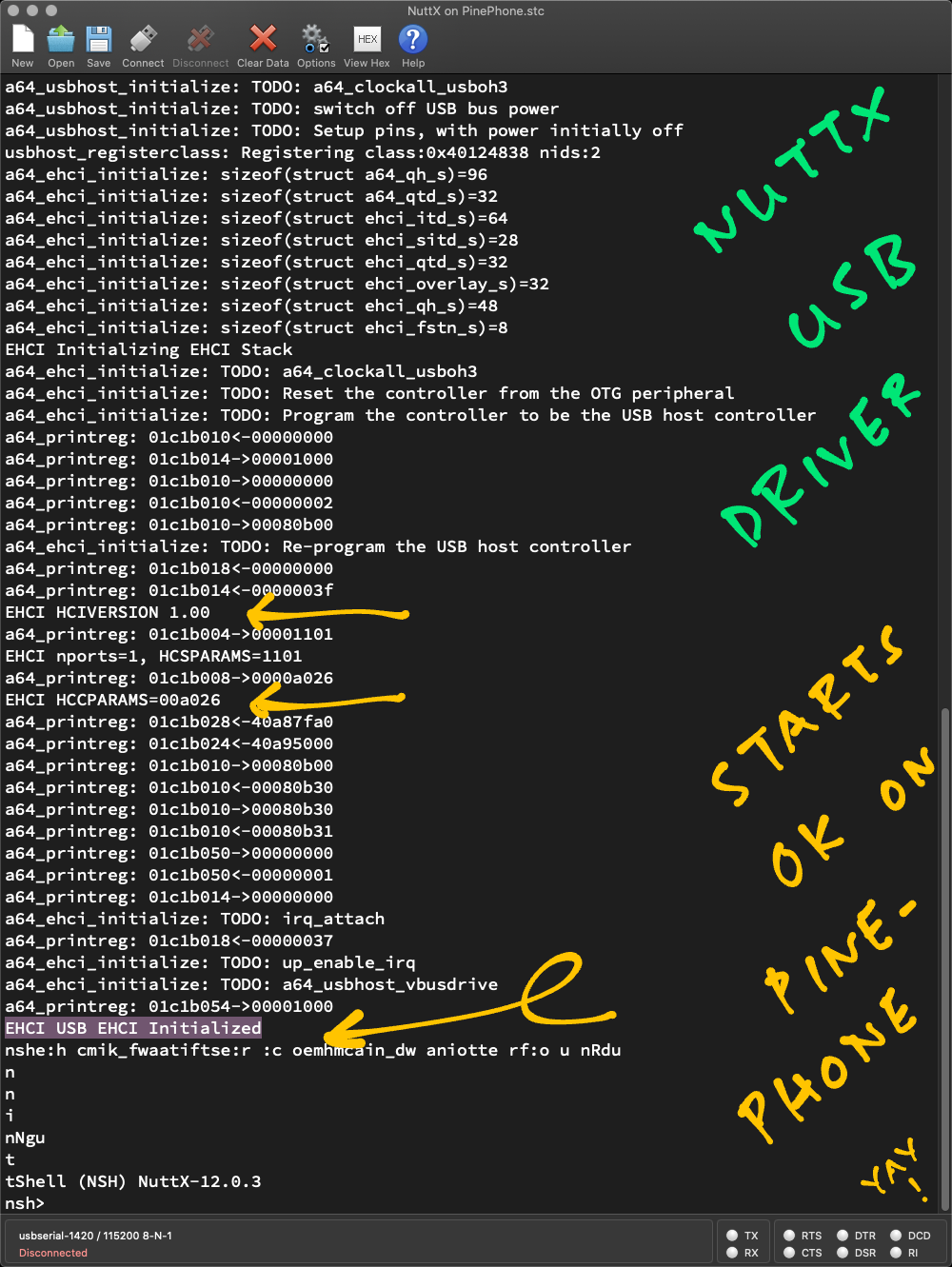
And now the NuttX EHCI Driver starts OK on PinePhone yay! 🎉
Here’s the log…
a64_usbhost_clk_enable:
  CLK_USB_PHY0,  CLK_USB_PHY1
  CLK_BUS_OHCI0, CLK_BUS_EHCI0
  CLK_USB_OHCI0, CLK_BUS_OHCI1
  CLK_BUS_EHCI1, CLK_USB_OHCI1

a64_usbhost_reset_deassert:
  RST_USB_PHY0,  RST_USB_PHY1
  RST_BUS_OHCI0, RST_BUS_EHCI0
RST_BUS_OHCI1, RST_BUS_EHCI1The log above shows NuttX enabling the USB Clocks and deasserting the USB Resets for…
USB PHY0 and USB PHY1
EHCI0 and OHCI0
EHCI1 and OHCI1
(Yeah this looks excessive. We probably need only USB PHY1, EHCI1 and OHCI1)
Then the NuttX EHCI Driver starts…
usbhost_registerclass:
  Registering class:0x40124838 nids:2
EHCI Initializing EHCI Stack
EHCI HCIVERSION 1.00
EHCI nports=1, HCSPARAMS=1101
EHCI HCCPARAMS=00a026
EHCI USB EHCI Initialized

NuttShell (NSH) NuttX-12.0.3
nsh> Which says that NuttX has successfully started the EHCI Controller. Yay!
But does the driver actually work?
We’ll find out soon as we test the NuttX EHCI Driver on PinePhone! Our test plan…
Enumerate the USB Devices on PinePhone
Handle the USB Interrupts on PinePhone
Verify the values of HCSPARAMS and HCCPARAMS
EHCI nports=1, HCSPARAMS=1101
EHCI HCCPARAMS=00a026The USB Descriptors for PinePhone’s LTE Modem are defined here…
Check out the progress here…
(I promised to reward myself with a Bread Machine when the NuttX EHCI Driver boots OK on PinePhone… Time to go shopping! 😀)
Today we made a significant breakthrough in supporting PinePhone USB on NuttX…
NuttX USB Driver now boots OK on PinePhone! 🎉
We tweaked slightly the NuttX Driver for USB Enhanced Host Controller Interface (EHCI)
Which is a lot simpler than USB On-The-Go (OTG)
Remember to enable the USB Clocks
And deassert the USB Resets
U-Boot Bootloader is a terrific resource for PinePhone USB
We’re one step closer to our dream of a NuttX Feature Phone!
Meanwhile please check out the other articles on NuttX for PinePhone…
Many Thanks to my GitHub Sponsors for supporting my work! This article wouldn’t have been possible without your support.
Special Thanks to TL Lim for the inspiring and invigorating chat! 🙂
Got a question, comment or suggestion? Create an Issue or submit a Pull Request here…