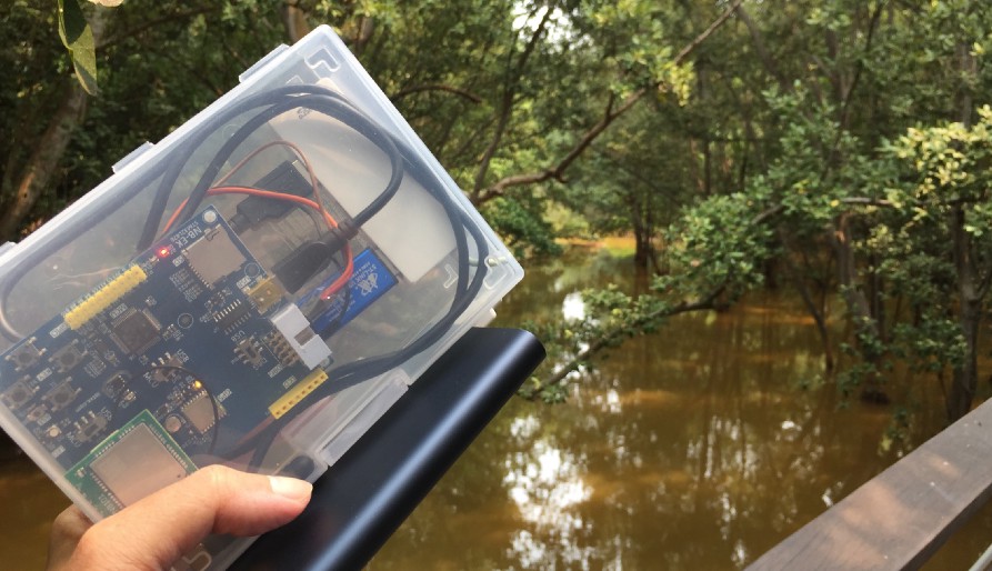
NB-IoT GPS Tracker running on the Ghostyu NB-EK-L476 Developer Kit with STM32L476RCT6 microcontroller, Quectel L70-R GPS module and Quectel BC95 NB-IoT module. Photo taken during the field test at Berlayer Creek Boardwalk (and mangrove swamp) in Singapore.
Build an NB-IoT GPS Tracker on STM32 L476 with Apache Mynewt and Embedded Rust
Plus Quectel L70-R GPS, Quectel BC95 NB-IoT modules and thethings.io

The Completed NB-IoT GPS Tracker Application showing geolocation and sensor data (raw temperature)
Let’s build an NB-IoT GPS Tracker! A simple gadget that determines its current location based on received GPS signals… And transmits the location to a server via NB-IoT.
We shall take an existing Apache Mynewt Embedded OS + Embedded Rust project from the article “Rust Rocks NB-IoT! STM32 Blue Pill with Quectel BC95-G on Apache Mynewt”… And extend it with a GPS module: Quectel L70-R.
The project already includes the Quectel BC95 NB-IoT module for transmitting sensor data in CoAP format over NB-IoT.
STM32 Blue Pill F103 doesn’t support floating-point computations in hardware, so it will be inefficient to compute floating-point latitude/longitude coordinates for the GPS module.
We’ll upgrade the STM32 F103 microcontroller to an STM32 L476 because it supports floating-point computations in hardware.
Thankfully there’s already a developer kit that contains the STM32 L476 microcontroller, Quectel L70-R GPS module and Quectel BC95 NB-IoT module… Ghostyu NB-EK-L476 Developer Kit, as described in the article “Quick Peek of Huawei LiteOS with NB-IoT on Ghostyu NB-EK-L476 Developer Kit (STM32L476RCT6)”. Perfect for our NB-IoT GPS Tracker!
Alternatively we may create your own kit based on the same STM32L476RCT6 microcontroller and Quectel modules.
Upgrading from STM32 Blue Pill F103 to L476
How hard is it to switch microcontrollers and migrate a Mynewt + Rust project from STM32 Blue Pill F103 to L476? As we shall find out… Not that hard!
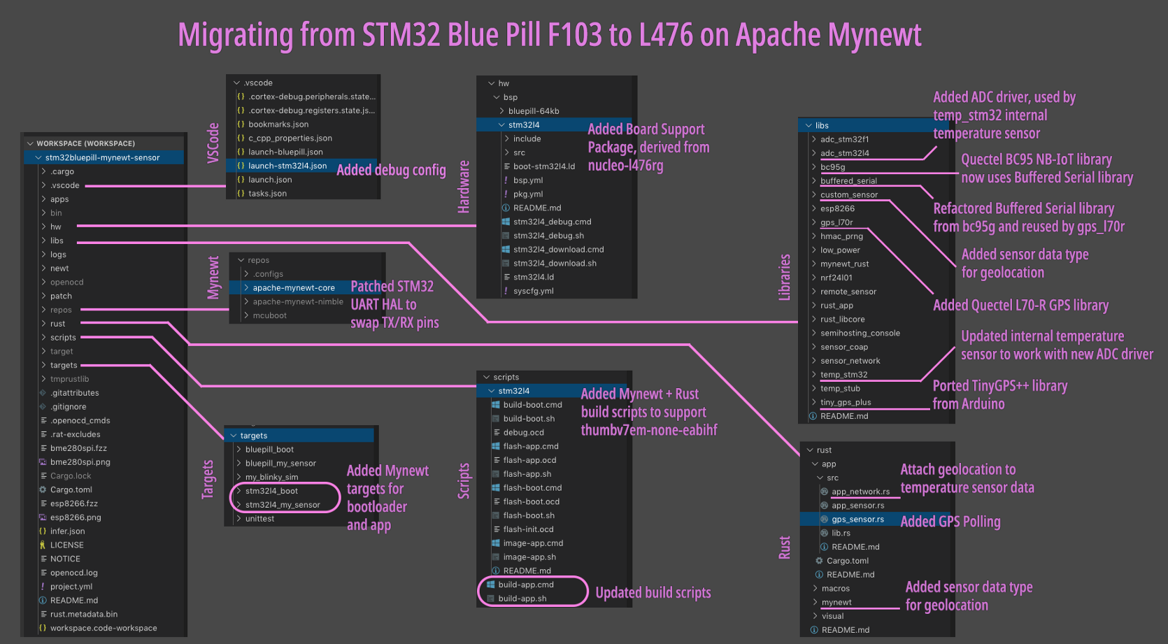
Below is the overall map of changes made to the Mynewt + Rust project while building the NB-IoT GPS Tracker. We’ll study each block in the subsequent sections.
Even if you’re new to Mynewt or Rust, feel free to skim this article! While building the NB-IoT GPS Tracker we made changes to a number of components in Mynewt OS and the Rust application… You’ll soon understand how the various parts of Mynewt and Rust work together to create an IoT gadget.
The complete source code is
available at the l476 branch of this repository…
Changes made for Mynewt Board Support Package
Mynewt Board Support Package
Every Mynewt project begins with a Board Support Package… Either take an existing one, or adapt from one. Check out the Board Support Packages
A Board Support Package contains information, scripts and drivers necessary to build Mynewt for our microcontroller and the associated peripherals on our microcontroller board: flash memory, LEDs, UART ports, …
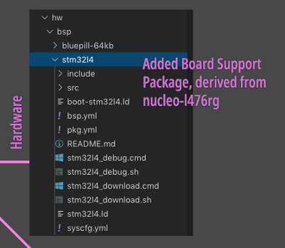
For this project, we customised
an existing Board Support Package nucleo-l476rg
by copying into hw/bsp/stm32l4
and renaming it. (The
previous project used the Board Support Package hw/bsp/bluepill-64kb)
Our board is similar to the Nucleo L476RG, except that the
Nucleo has 1 MB of flash ROM while ours has only 256 KB. Here’s how we resized the flash ROM by
editing hw/bsp/stm32l4/bsp.yml…
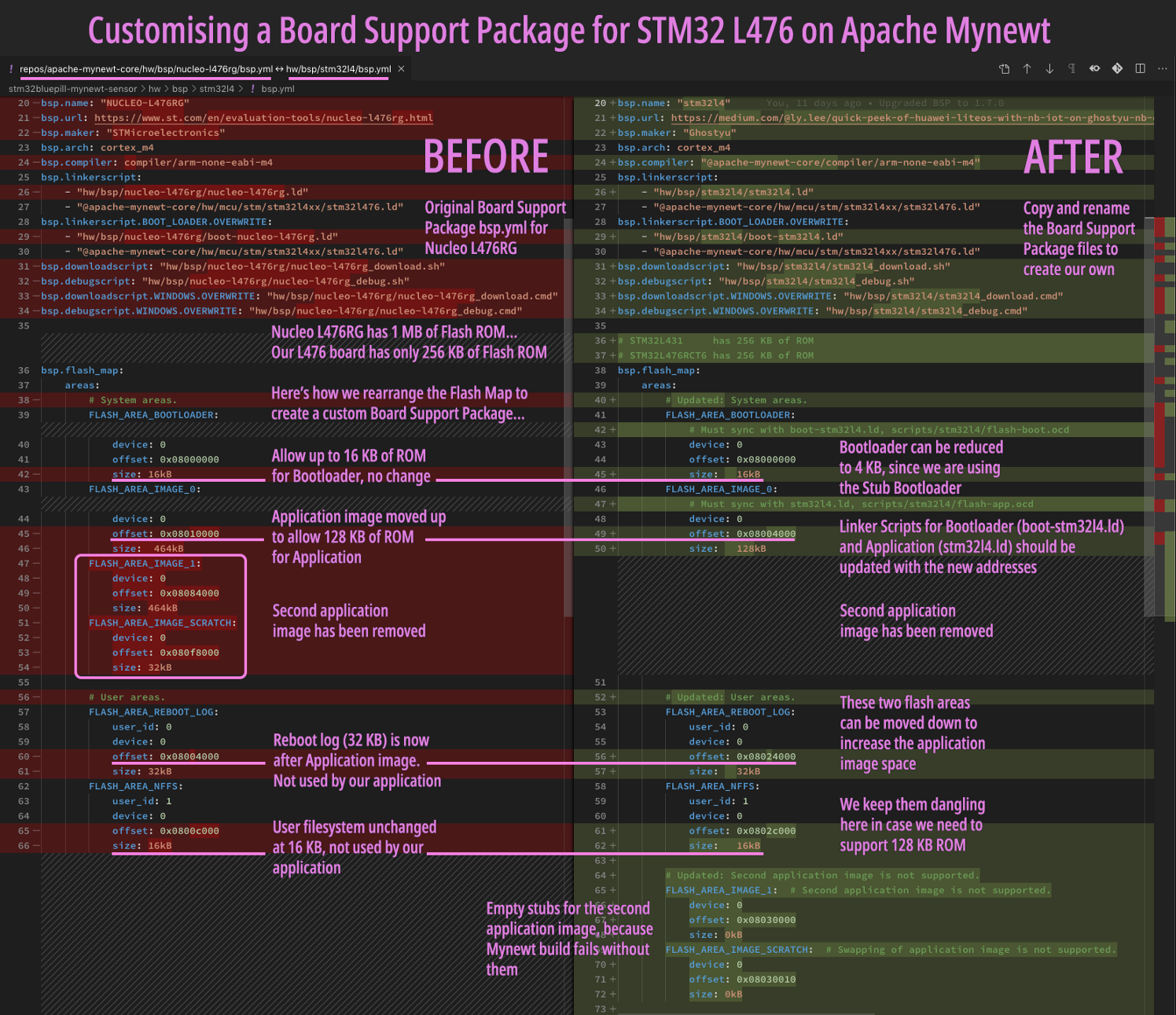
Customising a Board Support Package for STM32 L476 on Mynewt
The Board Support Package for the Nucleo defines two UART ports…
- The first is named
UART_0which points to portUSART2(connected to the Quectel BC95 NB-IoT module) - The second is named
UART_1which points to portUSART1(not used)
(Yep don’t confuse the Mynewt port name with the actual UART port)
For our board we need a third port…
UART_2which points to portLPUART1(connected to the Quectel L70-R GPS module)
Here’s how we add UART_2 by editing hw/bsp/stm32l4/syscfg.yml…
Adding UART_2 to Board Support Package Configuration. From https://github.com/lupyuen/stm32bluepill-mynewt-sensor/blob/l476/hw/bsp/stm32l4/syscfg.yml
But wait… This says that UART_2 will point to port USART3, not LPUART1!
Mynewt doesn’t have the driver code to support LPUARTs (Low Power UART) on the STM32 platform, so we used a quick hack…
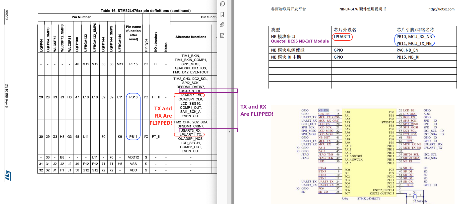
From STM32L476xx Datasheet https://www.st.com/resource/en/datasheet/stm32l476je.pdf and Ghostyu NB-EK-L476 Hardware Manual https://drive.google.com/file/d/14KZqMO6cj20eKqM85iJNth8vf_WbI5VM/view?usp=sharing
The STM32L476 Datasheet says that
LPUART1 and USART3 share
the same TX and RX pins,
except that they are flipped. (How odd!) STM32 programs may configure the UART
port such that the TX and RX pins are swapped… That’s how we disguised USART3 as LPUART1! More about
swapping TX and RX in a
while.
We complete the UART
customisation by adding the above code to hw/bsp/stm32l4/src/hal_bsp.c.
We are now ready to use our custom Board Support Package!
Changes made for Mynewt Hardware Abstraction Layer
Mynewt Hardware Abstraction Layer
Let’s talk about the Hardware Abstraction Layer (HAL) in Mynewt… Because there are two definitions of HAL used in Mynewt that may confuse us…
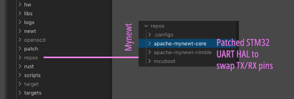
General HAL for STM32 in repos/apache-mynewt-core/hw/mcu/stm/stm32_common
1️⃣ The first type of HAL is the
General HAL that abstracts all the hardware on our microcontroller. The
General HAL enables us to write Mynewt applications that are portable across microcontrollers. Here’s
an example of a General HAL that abstracts the GPIO interface:
https://mynewt.apache.org/latest/os/modules/hal/hal_gpio/hal_gpio.html

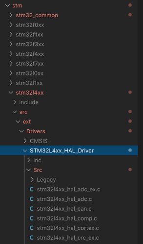
Vendor-Specific HAL for STM32 in repos/apache-mynewt-core/hw/mcu/stm/stm32l4xx
2️⃣ The second type of HAL is the
Vendor-Specific HAL provided by a microcontroller maker (like
STMicroelectronics) that abstracts the differences between various models of microcontrollers, e.g.
STM32 F103 vs L476. Here’s a Vendor-Specific HAL: https://github.com/apache/mynewt-core/tree/master/hw/mcu/stm/stm32l4xx/src/ext/Drivers/STM32L4xx_HAL_Driver/Src
From now on, when we mention “HAL” we refer to 1️⃣ General HAL.
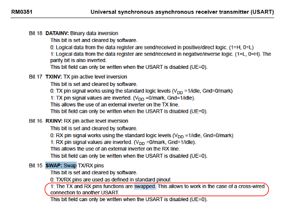
From STM32L4x6 Reference Manual: https://www.st.com/content/ccc/resource/technical/document/reference_manual/02/35/09/0c/4f/f7/40/03/DM00083560.pdf/files/DM00083560.pdf/jcr:content/translations/en.DM00083560.pdf
Recall that we need to patch the
UART HAL so that the TX and RX pins are swapped for port USART3 (so that it behaves like LPUART1). The STM32L4x6 Reference Manual
says that we may set the SWAP bit of UART register CR2 to swap the TX/RX pins.
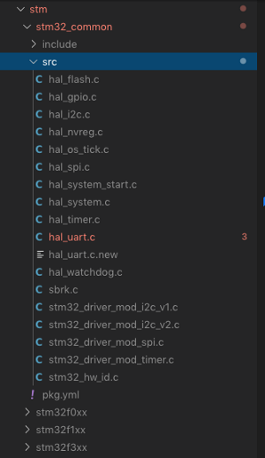
The UART HAL for STM32 is
implemented in apache-mynewt-core/hw/mcu/stm/stm32_common/src/hal_uart.c
(inside the repos folder of our project). Edit the file at line
468 to set the SWAP bit of CR2 like this…
You may refer to this patched version of hal_uart.c.
This patch depends on two conditions…
1️⃣ UART_2_SWAP_TXRX must be set to 1 in the syscfg.yml configuration file. Remember
that UART_2 is the Mynewt name for port USART3.
2️⃣ UART port must be USART3
Where is USART_CR2_SWAP defined? In the Vendor-Specific HAL.
In Visual Studio Code, the patch should look like this…
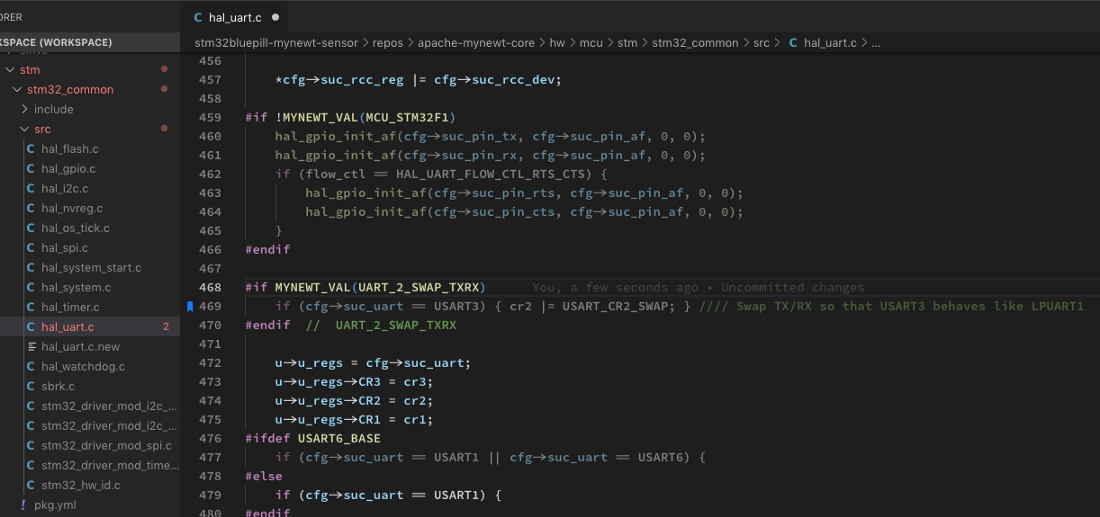
Patching hal_uart.c to swap TX/RX pins for USART3
Mynewt Targets

Changes made for Mynewt Targets
Mynewt Applications are designed to be portable across microcontrollers… The same application may be recompiled to run on STM32 Blue Pill F103, STM32 F476, or even BBC micro:bit (based on Nordic nRF51).
To compile a Mynewt Application
for a specific microcontroller board, we run the newt target
command like this…
This creates two targets stm32l4_boot (for the bootloader) and stm32l4_my_sensor (for the application)…
1️⃣ stm32l4_boot
is based on the Stub Bootloader located at apps/boot_stub
2️⃣ stm32l4_my_sensor
is based on our platform-indepedent Sensor Application located at apps/my_sensor_app
(which will be merged with the Rust application during compilation)
Both targets stm32l4_boot and stm32l4_my_sensor point to the same Board Support Package for STM32
L476 (hw/bsp/stm32l4),
so they will produce Bootloader and Application Firmware Images that will run on our STM32 L476 board.
(The
previous project used targets bluepill_boot
and bluepill_my_sensor)
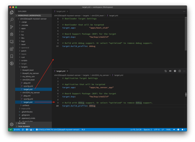
Instead of running the newt target command to create the targets, we may copy the target
folders ourselves to create the targets. Be sure to update target.yml to point to the correct Board Support Package (see
above).
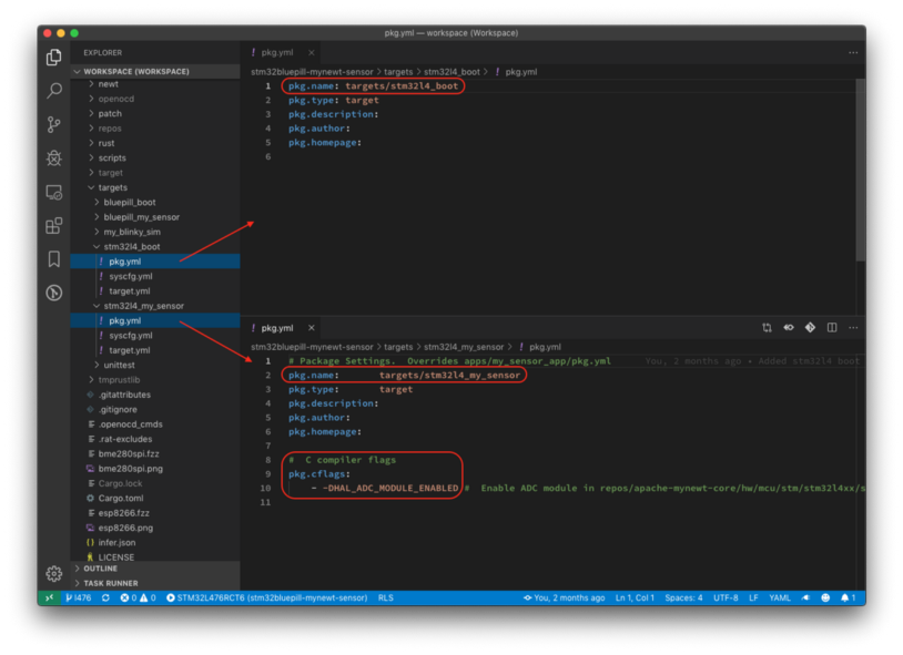
The package name pkg.name in pkg.yml should be
updated. C Compiler Directives and Linker Directives should be specified in pkg.yml, as shown above.
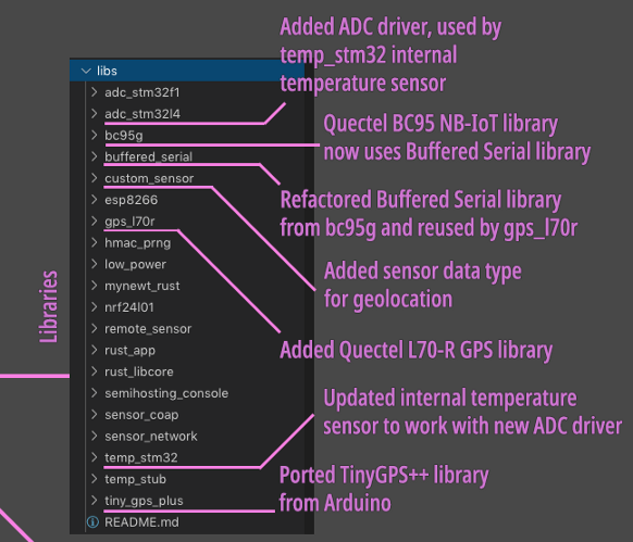
Changes made for Mynewt Libraries
Mynewt Libraries
Let’s look at the changes made to
the Mynewt libraries and drivers (located in libs)
that are used by our NB-IoT GPS Tracker application. Recall that the
previous project has already provided libraries for transmitting sensor data in CoAP format over
NB-IoT, also for reading the STM32 internal temperature sensor.
1️⃣ gps_l70r:
Driver for the Quectel L70-R GPS module. This is a new driver that connects to the UART port to
receive geolocation information (latitude, longitude, altitude) from the GPS module. It calls tiny_gps_plus
to parse the NMEA messages generated by the
GPS module.
2️⃣ tiny_gps_plus:
TinyGPS++ library that was
ported from Arduino. It parses NMEA messages generated by the GPS module to obtain geolocation
information.
3️⃣ custom_sensor:
We added a custom Sensor Data Type for the GPS geolocation, which contains latitude, longitude and
altitude. This enables the gps_l70r
GPS driver to be polled like any other sensor (e.g. internal temperature sensor) via Mynewt’s Sensor Framework.
4️⃣ mynewt_rust:
Helper functions were added to allow the Rust application to read the new Geolocation Sensor Data Type
5️⃣ buffered_serial:
Library that buffers data from the UART port for easier parsing. Used by the GPS driver gps_l70r
and the Quectel NB-IoT driver bc95g
6️⃣ adc_stm32l4:
We added this driver to support the Analog-To-Digital Converter (ADC) found in the STM32 L476
microcontroller. The ADC driver is used by the internal temperature sensor temp_stm32
7️⃣ temp_stm32:
This is the driver for the internal temperature sensor. The driver has been updated to use adc_stm32l4
to read the internal temperature sensor on the STM32 L476 microcontroller.
With these updates, our Rust application shall be able to poll the GPS sensor for the geolocation, attach the geolocation to the internal temperature sensor data, and transmit the geolocated sensor data to the CoAP Server at thethings.io over NB-IoT.
Application Configuration
Where do we configure the
settings for the libraries? In the System Configuration File for our Target Application targets/stm32l4_my_sensor/syscfg.yml…
Application Configuration. From https://github.com/lupyuen/stm32bluepill-mynewt-sensor/blob/l476/targets/stm32l4_my_sensor/syscfg.yml
(The System Configuration File
for the
previous project was at targets/bluepill_my_sensor/syscfg.yml)
Here we enable the drivers for
the GPS and NB-IoT modules, by setting GPS_L70R and BC95G to 1. We specify the
UART port for the GPS and NB-IoT modules like this…
GPS_L70R_UART: 0  #  Connect to Quectel L70R module on USART2
BC95G_UART:    2  #  Connect to Quectel BC95-G module on LPUART1
                  #  i.e. USART3 with TX/RX pins swapped
Why 0 and 2? Because the Mynewt
UART ports are named like this…
UART_0 → USART2
UART_1 → USART1
UART_2 → USART3
Recall that we need to swap the
TX/RX pins for port USART3
so that it behaves like LPUART1. We have applied a patch in
hal_uart.c that swaps the pins only if UART_2_SWAP_TXRX is set to 1…
# Swap TX/RX pins for USART3 so that USART3 behaves like LPUART1
UART_2_SWAP_TXRX: 1
On the Ghostyu developer kit, the GPS module is disabled by default. The GPS driver needs to set Pin PA1 to high to enable the GPS module. We specify the pin like this…
# GPIO Pin PA1 enables and disables the GPS module
GPS_L70R_ENABLE_PIN: MCU_GPIO_PORTA(1)
Rust Application
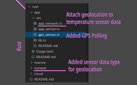
Changes made for Rust Application
In the previous project we have created an Embedded Rust application that polls the internal temperature sensor every 10 seconds and transmits the temperature to the CoAP server (at thethings.io). Now we’ll extend the Rust application to transmit the GPS Geolocation (latitude, longitude) together with the temperature.
We reused the Rust modules in
rust/app/src
from the previous application…
1️⃣ lib.rs:
Main program that starts the sensors and networking
2️⃣ app_sensor.rs:
Poll the internal temperature sensor temp_stm32 and call app_network.rs
to transmit the data
3️⃣ app_network.rs:
Compose a CoAP Message with a JSON Payload to transmit the temperature data to the CoAP server at
thethings.io
We added a new module gps_sensor.rs
that instructs Mynewt to poll our GPS sensor every 11 seconds. This is possible because our GPS driver
gps_l70r
has been integrated with Mynewt’s Sensor Framework so
that it works like any other sensor (such as the internal temperature sensor).
Now we have two sources of sensor data in our Rust application…
1️⃣ Internal Temperature Sensor Data, generated by the temp_stm32
driver
2️⃣ GPS
Geolocation (latitude, longitude, altitude), generated by the gps_l70r
driver
To conserve NB-IoT packets, we’ll
aggregate the two types of sensor data and transmit as a single CoAP message. That’s why the Sensor
Listeners for both sensors have been updated to forward the polled sensor data to a new function aggregate_sensor_data() defined in app_network.rs…
When aggregate_sensor_data() receives a GPS Geolocation, it doesn’t
transmit the data to the server. Instead it stores the GPS Geolocation.
When aggregate_sensor_data() receives the temperature sensor data, it
attaches the stored GPS Geolocation to the sensor data, and transmits the geolocated sensor data like
this…
{ "values": [
   { "key"  : "t",
     "value": 960,
     "geo"  : { "lat": 1.2701, "long": 103.8078 }}
     ...
]}
This JSON Payload format is
specified by thethings.io for transmitting sensor data (temperature t = 960) with attached geolocation (latitude = 1.2701, longitude = 103.8078).
The Rust code for creating the
JSON Payload is exactly the same as before, based on the coap!
macro…
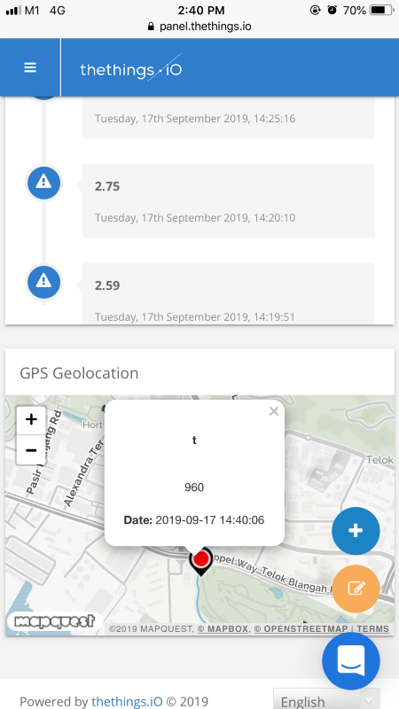
Geolocated Sensor Data rendered in a dashboard at thethings.io
How is this possible? Because the
coap!
macro has been updated to emit the GPS Geolocation
attached to the sensor data in val (if the GPS Geolocation
exists).
The screen shows how the Geolocated Sensor Data transmitted by our device would be rendered in a dashboard at thethings.io.
That’s the power of creating a
Domain-Specific Language (like coap!) in Rust… We simply focus
on the intent of transmitting sensor data, and let the macro decide how to generate the right payload
to match our intent.
One more enhancement implemented in the Mynewt Rust Wrapper: The polling of Mynewt sensors in the Rust application has been made simpler by introducing Rust Iterators…
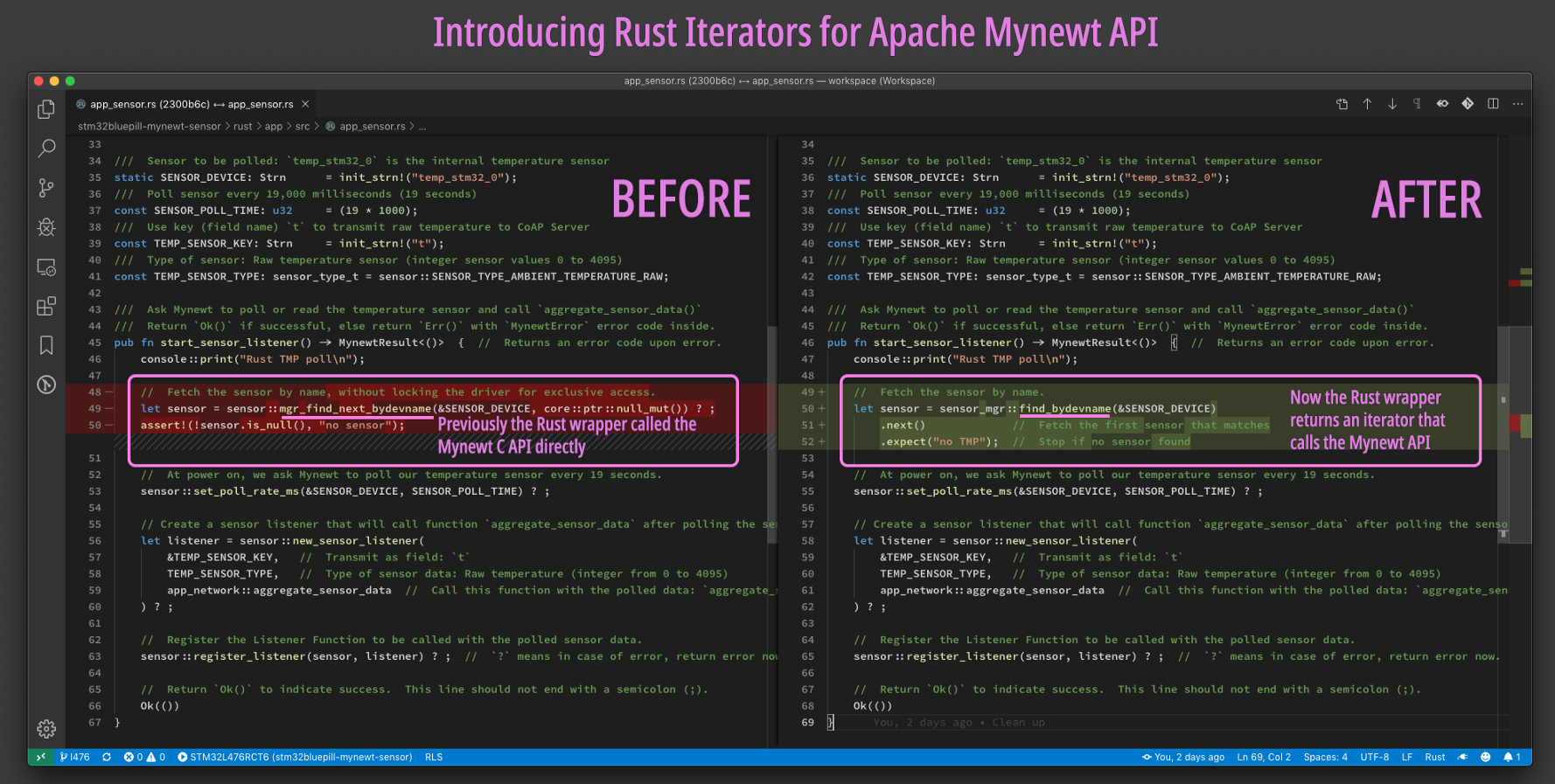
Rust Iterators for polling Mynewt sensors. From https://github.com/lupyuen/stm32bluepill-mynewt-sensor/blob/l476/rust/app/src/app_sensor.rs
Mynewt Build and Flash Scripts
Changes made for Mynewt Build and Flash Scripts
Mynewt provides the command-line tool newt
for building the firmware image and flashing it to the microcontroller. On Windows, newt requires the MSYS2 and MinGW toolchains to be
installed.
I wanted to simplify the
installation of the Mynewt build tools on Windows (and make them more robust), so I chose to write my
own build and flash scripts based on pure Windows, without MSYS2 and MinGW. Earlier I have
experimented with newt on Windows Subsystem for Linux
but the performance was awful so I dropped it.
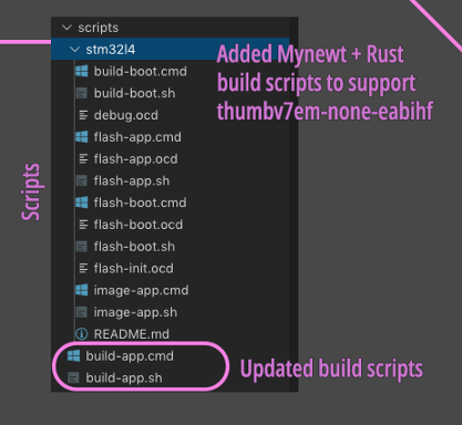
The custom build scripts for
STM32 L476 are located in the scripts/stm32l4
folder (except for build-app, which is located in scripts).
The *.cmd scripts are for Windows, *.sh scripts are for macOS and Linux (though not extensively tested
for Linux). *.ocd are the OpenOCD scripts for flashing
and debugging (they control the ST-Link interface).
1️⃣ build-boot.cmd, .sh:
Build the bootloader by running newt build stm32l4_boot
2️⃣ build-app.cmd, .sh:
Build the application by running newt build stm32l4_my_sensor.
Also builds the Rust application and injects the compiled Rust code into the build.
Previously the Rust build for
STM32 Blue Pill F103 was targeted for thumbv7m-none-eabi (Arm
Cortex M3), now the Rust build for STM32 L476 is targeted for thumbv7em-none-eabihf (Arm Cortex M4 with Hardware Floating-Point)
3️⃣ image-app.cmd, .sh:
Create the application firmware image: newt create-image -v stm32l4_my_sensor 1.0.0
4️⃣ flash-boot.cmd, .sh:
Flash the bootloader with OpenOCD
5️⃣ flash-boot.ocd:
OpenOCD script for flashing the bootloader
6️⃣ flash-app.cmd, .sh:
Flash the application with OpenOCD
7️⃣ flash-app.ocd:
OpenOCD script for flashing the application
8️⃣ flash-init.ocd:
OpenOCD initialisation script called by flash-boot.ocd and flash-app.ocd
9️⃣ debug.ocd:
OpenOCD script for debugging the application. Called by the Cortex-Debug Extension in
.vscode/launch-stm32l4.json
The newt command in the Windows scripts refer to the Windows build of newt,
which works without MSYS2 and MinGW.
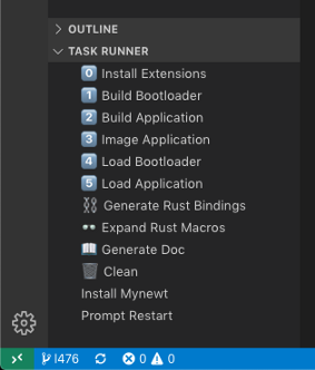
Visual Studio Code Tasks in the Task Runner
The above scripts are linked into
.vscode/tasks.json
so that they will appear as Tasks in Visual Studio Code.
If we’re using the Task Runner Extension, the tasks will appear like this.
(The custom build and flash
scripts from the
previous project are located in the scripts
folder)
Visual Studio Code Configuration
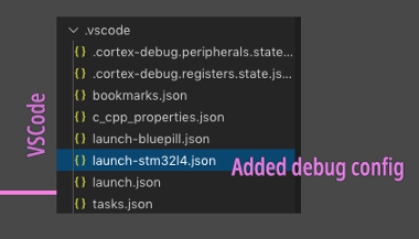
Changes made for Visual Studio Code Configuration
Cortex-Debug is the debugger
we’re using in Visual Studio Code to debug our application. We added a new debugger configuration
.vscode/launch-stm32l4.json
for STM32 L476.
The debugger configuration
specifies the OpenOCD scripts and GDB commands for debugging the
application. Note that launch.json,
the current debugger configuration, is overwritten by launch-stm32l4.json
whenever the application is rebuilt. So we should never edit launch.json.
Cortex-Debug Configuration. From https://github.com/lupyuen/stm32bluepill-mynewt-sensor/blob/l476/.vscode/launch-stm32l4.json
(The debugger configuration from
the
previous project is at .vscode/launch-bluepill.json)
Connect the Hardware
To build the NB-IoT GPS Tracker we’ll need the following hardware…
1️⃣ Ghostyu NB-EK-L476 Developer Kit, as described in the article “Quick Peek of Huawei LiteOS with NB-IoT on Ghostyu NB-EK-L476 Developer Kit (STM32L476RCT6)”
The kit includes the STM32L476RCT6 microcontroller, Quectel BC95 NB-IoT module (with antenna) and Quectel L70-R GPS module (with antenna).
Alternatively: You may assemble your own kit based on the same STM32 microcontroller and Quectel modules.
Remember to select a Quectel NB-IoT module that works with your local NB-IoT Frequency Band. You may consider this Quectel BC95-G Global NB-IoT Module (breakout board with antenna), which supports all global bands.
To connect the components in your custom kit, refer to the Ghostyu NB-EK-L476 schematics. Note that the Quectel NB-IoT module may require additional power, like tapping the 5V pin from ST-Link instead of sharing the ST-Link’s 3.3V pin with the microcontroller.
2️⃣ ST-Link V2
USB Adapter: Under $2, search AliExpress for st-link v2
3️⃣ NB-IoT SIM from your local NB-IoT network operator. Many thanks to StarHub for sponsoring the NB-IoT SIM that I used for this tutorial!
Pins connected from the SWD Debug Port to ST-Link: SWDIO, SWCLK, VCC, GND
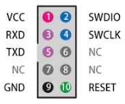
SWD Debug Port on Ghostyu NB-EK-L476
Connect the following pins from
the SWD Debug Port to ST-Link: SWDIO, SWCLK, VCC, GND.
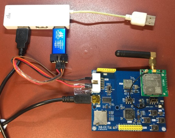
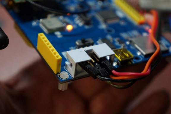
Ghostyu STM32 L476 Development Kit powered by both ST-Link and micro-USB port. At top left is a USB hub.
For the Ghostyu NB-EK-L476, you need to connect the micro-USB port on the board to another USB port on your computer. This means that the board will have two power sources: 3.3V power from ST-Link, and 5V power from micro-USB port. This ensures that the NB-IoT module will have sufficient power.
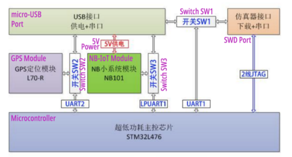
NB-IoT Module Power Supply for Ghostyu NB-EK-L476. From https://drive.google.com/file/d/14KZqMO6cj20eKqM85iJNth8vf_WbI5VM/view?usp=sharing
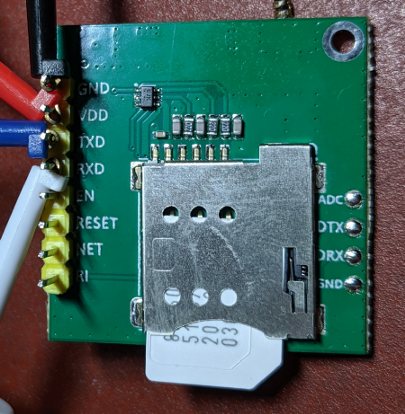
SIM partially exposed to show the unusual orientation
Insert the NB-IoT SIM into the Quectel NB-IoT Breakout Board according to the orientation shown in the photo. (Yes the SIM notch faces outward, not inward)
Remember: Always connect the antenna before powering up the NB-IoT module!
If you’re using Windows: Make sure that the ST-Link Driver has been installed before connecting ST-Link to your computer
Install and Run the NB-IoT GPS Tracker
Follow the instructions in this article to install, build and run our application on the STM32 L476 development board (or equivalent).
While running the application, the Console Log should look like this…
Adapter Output Log from https://github.com/lupyuen/stm32bluepill-mynewt-sensor/blob/l476/logs/standalone-node.log
Here you can see the program reading the internal temperature sensor.
The temperature sensor data is combined with the GPS geolocation into a JSON Payload.
The JSON Payload is then transmitted as a CoAP Message to the CoAP server at thethings.io.
In the Console Log, there is a
URL displayed: http://blue-pill-geolocate.appspot.com/...
Clicking this URL opens a web page that displays the computed temperature (in degrees Celsius) and the GPS geolocation, based on the sensor data received by thethings.io from your device over NB-IoT. This URL is randomly-generated each time we restart our device.
We have installed a script at thethings.io that
pushes the computed temperature and geolocation to blue-pill-geolocate.appspot.com. For more details, check the section
“Advanced Topic: WiFi Geolocation with thethings.io and Google App Engine” in the
article “Connect STM32 Blue Pill to ESP8266 with Apache Mynewt”.
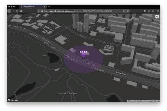
Computed temperature and the GPS geolocation
Does the transmission of geolocation work when the device is on the move (say, when mounted on a vehicle?) If the device moves between NB-IoT cells, will the transmission still succeed?
Yes! I have tested the NB-IoT GPS Tracker while walking around… Geolocation updates are indeed transmitted correctly to thethings.io as I walk.
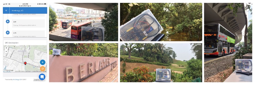
Field testing of the NB-IoT GPS Tracker
Here’s a video demo of the NB-IoT GPS Tracker…
thethings.io Configuration
If you’re happy to view the
sensor data using my server at blue-pill-geolocate.appspot.com,
you may skip this section. If you wish to configure your own account for thethings.io, read on…
Follow the steps in the three
videos below to configure your thethings.io account and install the Cloud Code Scripts. Click CC to view the instructions.
Note: There is one additional Cloud Code Function to be installed: push_sensor_data.
Copy the code from this link to create a new
Cloud Code Function named push_sensor_data.
The Thing Token should be updated
in the COAP_URI setting of the System Configuration File targets/stm32l4_my_sensor/syscfg.yml
thethings.io Configuration: Part 1 of 3. Click CC to view the instructions.
thethings.io Configuration: Part 2 of 3. Click CC to view the instructions.
thethings.io Configuration: Part 3 of 3. Click CC to view the instructions.
At the dashboard page, create a new Widget with the following settings…
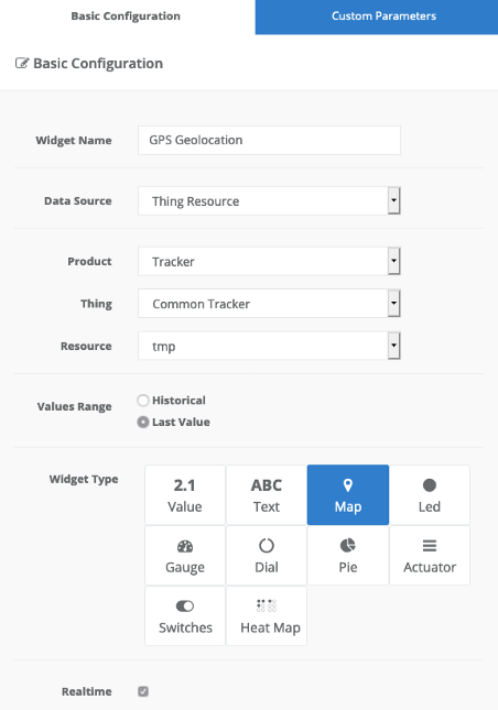
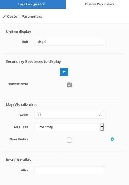
The geolocated temperature will be shown in the Widget. Here’s how it looks…
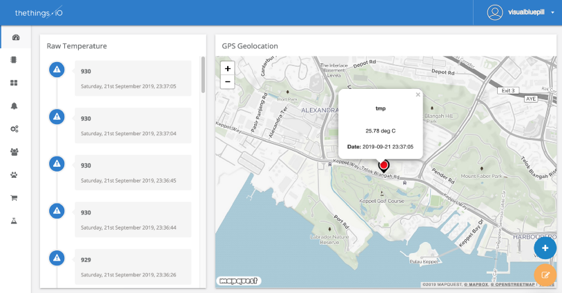
thethings.io dashboard with geolocated temperature sensor data
Here’s a video demo of thethings.io dashboard with geolocated temperature sensor data…
Video demo of thethings.io dashboard with geolocated temperature sensor data
What’s Next?
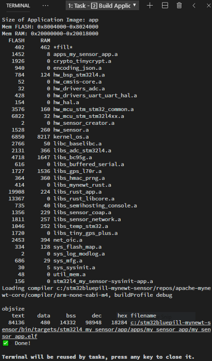
RAM and ROM usage in Application Build Log. From https://github.com/lupyuen/stm32bluepill-mynewt-sensor/blob/l476/logs/build-application.log
We have created an NB-IoT GPS Tracker in only 84 KB of Flash ROM (with debugging symbols included). Mighty impressive considering that it includes Mynewt Embedded OS and the Embedded Rust Libraries!
STM32 L476 is definitely a good choice for building an NB-IoT GPS Tracker. Mynewt did a great job of shielding the microcontroller-specific details and making embedded applications truly portable. And the application was created with only a few lines of Rust application code… Rust is incredibly productive for creating embedded applications!
For my next article I shall be taking a break from STM32 (since we have proved that it’s so easy to port Mynewt applications across STM32 microcontrollers)… And explore Nordic nRF52832 with Mynewt and Rust!