📝 9 Jun 2021
How is our firmware loaded into BL602’s flash memory?
How does BL602 prevent tampering of firmware?
All this and much, much more shall be explained as we learn about the Boot2 Bootloader for the BL602 RISC-V + WiFi SoC.
Let’s ponder what happens when we flash to BL602 the firmware that we have built…
(We’ll call it the Application Firmware)
Sounds easy! We transfer the Application Firmware from our computer to BL602 (over USB)…
Then BL602 writes the Application Firmware to flash memory. Right?
Not quite. We talked about flashing Application Firmware in the article…
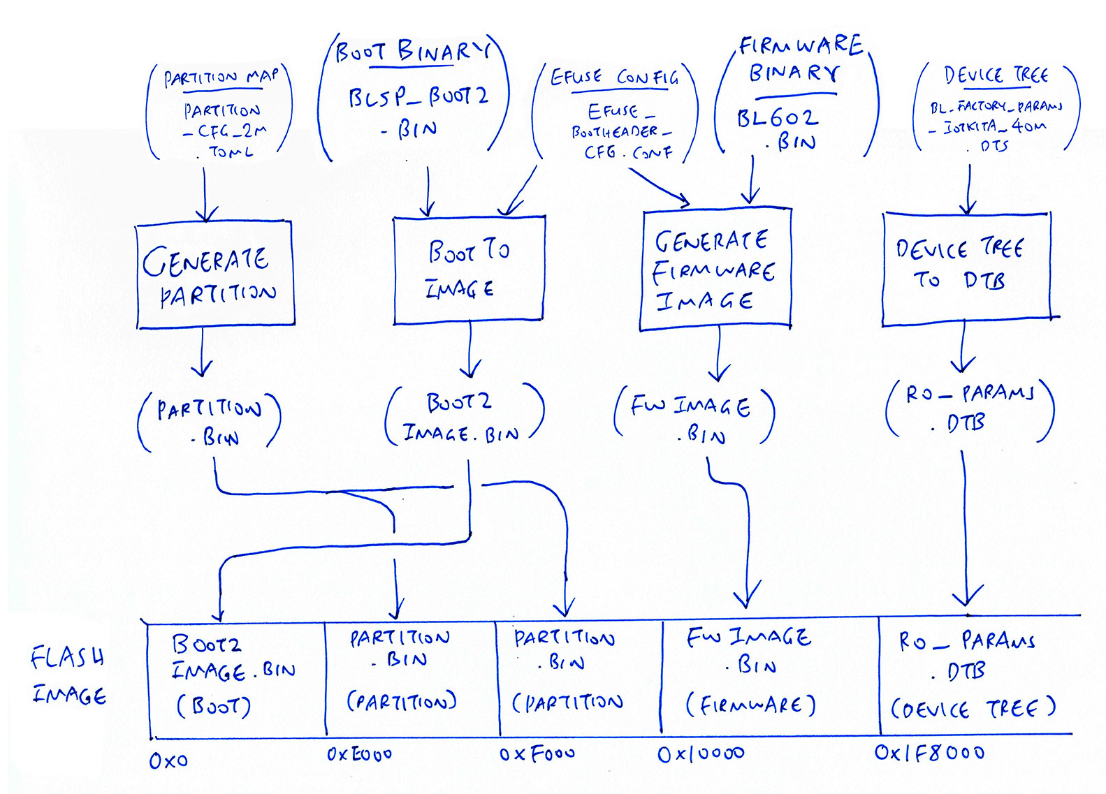
During flashing, we transfer a Flashing Image from our computer to BL602 over USB, helped by the EFlash Loader…
The Flashing Image contains…
Boot2 Bootloader blsp_boot2.bin
(Written to the Flashing Image as boot2image.bin)
Application Firmware bl602.bin
(Written to the Flashing Image as fwimage.bin)
Partition Table partition.bin and Device Tree ro_params.dtb
Here’s how the Flashing Image is constructed…
Why is the Boot2 Bootloader transferred to BL602 during flashing?
During flashing, our Application Firmware isn’t written directly to BL602’s XIP Flash Memory.
Instead, BL602 runs the Boot2 Bootloader which…
Extracts our Application Firmware from the transferred Flashing Image
Writes our Application Firmware to XIP Flash Memory
Starts our Application Firmware from XIP Flash Memory
XIP means Execute In Place.
It refers to the External Flash Memory (SPI Flash) that will store our executable firmware code.
Isn’t External Flash Memory too slow for running firmware code?
XIP uses Cache Memory (RAM) to speed up access to External Flash Memory.
This Cache Memory makes it possible to run firmware code stored in Flash Memory.
Where is the Boot2 Bootloader located?
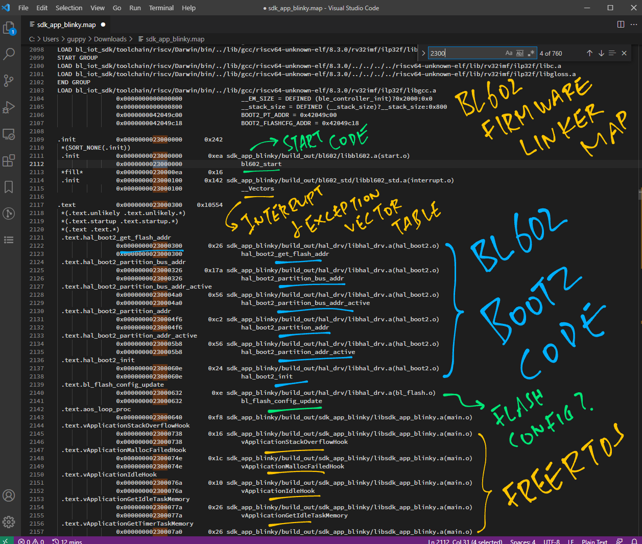
BL602 runs the Boot2 Bootloader from XIP Flash Memory at address 0x2300 0000.
Yep it’s the same address as our Application Firmware!
So the Bootloader overwrites itself by our Application Firmware?
Not quite. We’ll learn later how the Boot2 Bootloader remaps the XIP Flash Memory to start the Application Firmware.
Is Boot2 really a Bootloader?
On other microcontrollers, the Bootloader is the first thing that runs when powered on. (Before jumping to the Application Firmware)
On BL602, the Boot2 Bootloader also installs new Application Firmware into XIP Flash Memory.
(Somewhat similar to the MCUBoot Bootloader for PineTime Smart Watch)
Why so complicated?
BL602’s Boot2 Bootloader allows Application Firmware to be flashed securely to XIP Flash Memory…
Boot2 Bootloader supports flashing of AES-Encrypted Application Firmware
(So it’s possible to push encrypted firmware updates over-the-air)
Boot2 Bootloader can use Digital Signatures to verify that the Application Firmware is authentic
(Prevents tampering of firmware updates)
We’ll learn more about BL602 firmware security in a while.
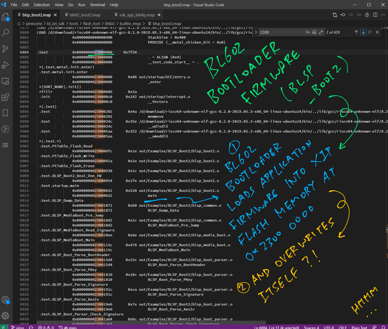
BL602 Boot2 Bootloader runs at address 0x2300 0000
To understand the BL602 Bootloader, let’s look at the code inside…
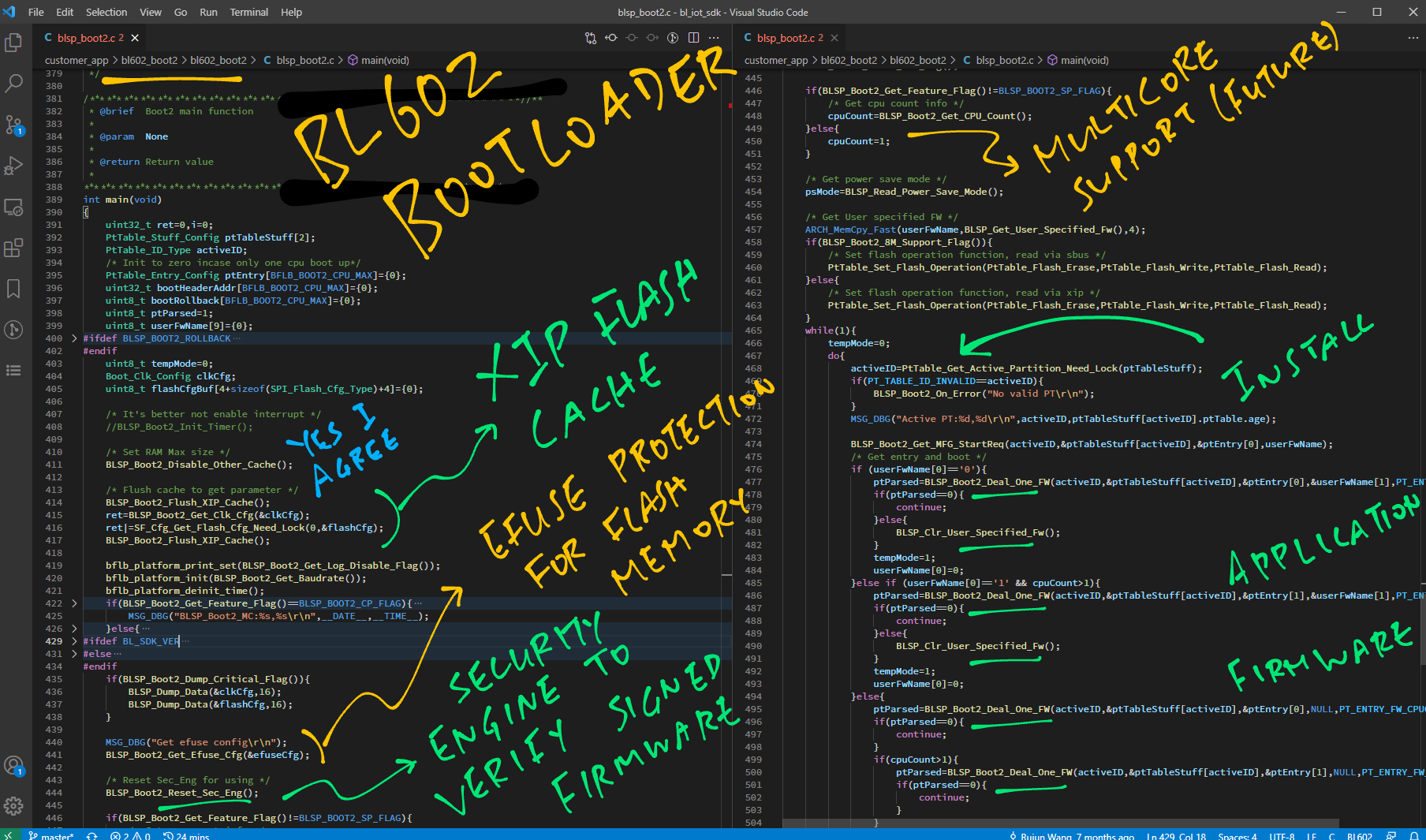
The Bootloader starts by fetching the Clock Configuration and SPI Flash Configuration from the Flashing Image (See this)
//  SPI Flash Configuration
SPI_Flash_Cfg_Type flashCfg;

//  EFuse Hardware Configuration
Boot_Efuse_HW_Config efuseCfg;

int main(void) {
    ...
  //  It's better not enable interrupt
  //  BLSP_Boot2_Init_Timer();

  //  Set RAM Max size
  BLSP_Boot2_Disable_Other_Cache();

  //  Flush cache to get parameter
  BLSP_Boot2_Flush_XIP_Cache();

  Boot_Clk_Config clkCfg;  //  Clock Configuration
  ret = BLSP_Boot2_Get_Clk_Cfg(&clkCfg);

  ret |= SF_Cfg_Get_Flash_Cfg_Need_Lock(0, &flashCfg);
  BLSP_Boot2_Flush_XIP_Cache();
Next the Bootloader initialises the Hardware Platform…
  bflb_platform_print_set(BLSP_Boot2_Get_Log_Disable_Flag());

  bflb_platform_init(BLSP_Boot2_Get_Baudrate());

  bflb_platform_deinit_time();
We fetch the EFuse Configuration (for decrypting the Application Firmware and for verifying the firmware signature)
  MSG_DBG("Get efuse config\r\n");
  BLSP_Boot2_Get_Efuse_Cfg(&efuseCfg);
(We’ll see BLSP_Boot2_Get_Efuse_Cfg in a while)
We reset the Security Engine (for AES Encryption operations)
  //  Reset Sec_Eng for using
  BLSP_Boot2_Reset_Sec_Eng();
The Bootloader supports multicore CPUs. (Each core will start the Application Firmware with different parameters)
BL602 is a single-core CPU, so the CPU Count will be set to 1…
  if (BLSP_Boot2_Get_Feature_Flag() != BLSP_BOOT2_SP_FLAG) {
    //  Get CPU count info
    cpuCount = BLSP_Boot2_Get_CPU_Count();
  } else {
    cpuCount = 1;
  }
We fetch the Application Firmware Name from the Flashing Image.
Our Application Firmware is always named “FW” (See this)
  //  Get power save mode
  psMode = BLSP_Read_Power_Save_Mode();

  //  Get User specified firmware
  uint8_t userFwName[9] = {0};  //  Firmware Name
  ARCH_MemCpy_Fast(
    userFwName,
    BLSP_Get_User_Specified_Fw(),
    4);
We register the functions that will be called to Erase, Write and Read the Partition Table…
  if (BLSP_Boot2_8M_Support_Flag()) {
    //  Set flash operation function, read via sbus
    PtTable_Set_Flash_Operation(PtTable_Flash_Erase,
      PtTable_Flash_Write, PtTable_Flash_Read);
  } else {
    //  Set flash operation function, read via xip
    PtTable_Set_Flash_Operation(PtTable_Flash_Erase,
      PtTable_Flash_Write, PtTable_Flash_Read);
  }
(Yes the parameters for both calls of PtTable_Set_Flash_Operation are identical)
The Bootloader enters two loops…
Outer Loop “while”: Loops until the writing (or rollback) of Application Firmware is complete
Inner Loop “do”: Loops through the Partition Table Entries until the writing of Application Firmware to XIP Flash Memory is complete
  while (1) {
    tempMode = 0;
    do {
Let’s probe the inner loop…
We fetch the next Partition Table Entry from the Flashing Image…
      activeID = PtTable_Get_Active_Partition_Need_Lock(ptTableStuff);
      if (PT_TABLE_ID_INVALID==activeID){ BLSP_Boot2_On_Error("No valid PT\r\n"); }

      BLSP_Boot2_Get_MFG_StartReq(
        activeID,
        &ptTableStuff[activeID],
        &ptEntry[0],
        userFwName);
We skip these two conditions because our Application Firmware is named “FW” and we’re running on a single-core CPU…
      //  Get entry and boot
      if (userFwName[0] == '0') {
        //  Skip this code because our Firmware Name is "FW"
        ...
      } else if (userFwName[0] == '1' && cpuCount > 1) {
        //  Skip this code because our CPU Count is 1 (single core)
        ...
      }
Now comes the fun part!
The Bootloader extracts the Application Firmware (from the Flashing Image) and writes it to XIP Flash Memory…
      else {
        ptParsed = BLSP_Boot2_Deal_One_FW(
          activeID,
          &ptTableStuff[activeID],
          &ptEntry[0],
          NULL,
          PT_ENTRY_FW_CPU0);

        if (ptParsed == 0) { continue; }
        if (cpuCount > 1) {
          //  Skip this code because our CPU Count is 1 (single core)
          ...
        }
      }
We’ll study BLSP_Boot2_Deal_One_FW in the next chapter.
The Inner Loop repeats until it has located and processed the Application Firmware…
      ptParsed = 1;
    } while (ptParsed == 0);
Now that the Application Firmware has been written to XIP Flash Memory, let’s get ready to start the Application Firmware!
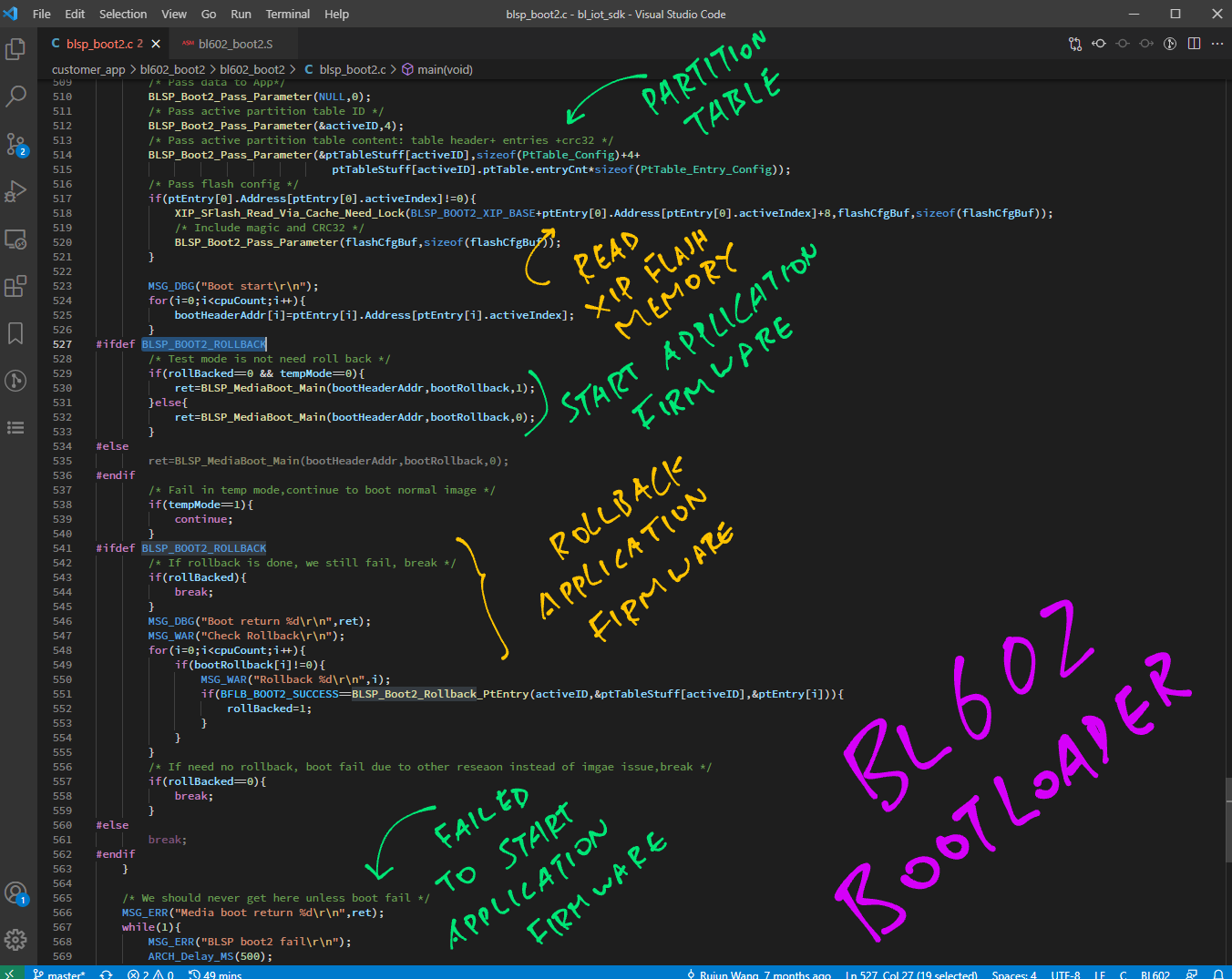
We stage the Partition Table Entry that will be passed to the firmware…
    //  Pass data to App
    BLSP_Boot2_Pass_Parameter(NULL, 0);

    //  Pass active partition table ID
    BLSP_Boot2_Pass_Parameter(&activeID, 4);

    //  Pass active partition table content: table header + entries + crc32
    BLSP_Boot2_Pass_Parameter(
      &ptTableStuff[activeID],
      sizeof(PtTable_Config) + 4
        + ptTableStuff[activeID].ptTable.entryCnt
          * sizeof(PtTable_Entry_Config));
We pass the Flash Configuration too…
    //  Pass flash config
    if (ptEntry[0].Address[ptEntry[0].activeIndex] != 0) {
      XIP_SFlash_Read_Via_Cache_Need_Lock(
        BLSP_BOOT2_XIP_BASE
          + ptEntry[0].Address[ptEntry[0].activeIndex]
          + 8,
        flashCfgBuf,
        sizeof(flashCfgBuf));

      //  Include magic and CRC32
      BLSP_Boot2_Pass_Parameter(
        flashCfgBuf,
        sizeof(flashCfgBuf));
    }
We initialise the Boot Header for each core (in a multicore CPU)
    MSG_DBG("Boot start\r\n");
    for (i = 0; i < cpuCount; i++) {
      bootHeaderAddr[i] = ptEntry[i].Address[ptEntry[i].activeIndex];
    }
Finally we jump to the Application Firmware that has been written to XIP Flash Memory…
#ifdef BLSP_BOOT2_ROLLBACK  //  This is true
    //  Test mode is not need roll back
    if (rollBacked == 0 && tempMode == 0) {
      ret = BLSP_MediaBoot_Main(bootHeaderAddr, bootRollback, 1);
    } else {
      ret = BLSP_MediaBoot_Main(bootHeaderAddr, bootRollback, 0);
    }
#else  //  This is false
    ...
#endif
    //  Fail in temp mode, continue to boot normal image
if (tempMode == 1) { continue; }(BLSP_BOOT2_ROLLBACK is defined because the Bootloader supports firmware rollback)
We’ll cover BLSP_MediaBoot_Main in a while.
What happens if the Bootloader fails to update or start the new Application Firmware?
The Bootloader will rollback the Application Firmware and restore the previous version into XIP Flash Memory…
#ifdef BLSP_BOOT2_ROLLBACK  //  This is true
    //  If rollback is done, we still fail, break
    if (rollBacked) { break; }
    for (i = 0; i < cpuCount; i++) {
      if (bootRollback[i] != 0) {
        if (BFLB_BOOT2_SUCCESS == BLSP_Boot2_Rollback_PtEntry(
          activeID, &ptTableStuff[activeID], &ptEntry[i])) {
          rollBacked = 1;
        }
      }
    }
    //  If need no rollback, boot fail due to other reseaon instead of imgae issue, break
    if (rollBacked == 0) { break; }
#else  //  This is false
    ...
#endif
  }
(The Outer Loop ends here)
The Main Function of the Bootloader will never return, because the Bootloader always jumps to the Application Firmware…
  //  We should never get here unless boot fail
  MSG_ERR("Media boot return %d\r\n",ret);
  while (1) {
    MSG_ERR("BLSP boot2 fail\r\n");
    ARCH_Delay_MS(500);
  }
}
That’s how the Bootloader installs our Application Firmware and starts the firmware!
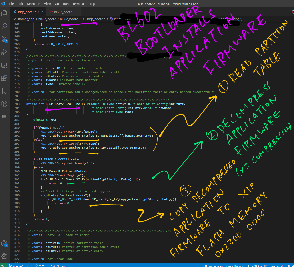
As we’ve seen, the Bootloader calls BLSP_Boot2_Deal_One_FW to…
Extract the Application Firmware from the Flashing Image
Write the Application Firmware to XIP Flash Memory
Here’s how it works: blsp_boot2.c
//  Boot2 deal with one firmware.
//  Return 0 for partition table changed, need re-parse.
//  Return 1 for partition table or entry parsed successfully.
static int BLSP_Boot2_Deal_One_FW(
  PtTable_ID_Type activeID,       //  Active partition table ID
  PtTable_Stuff_Config *ptStuff,  //  Pointer of partition table stuff
  PtTable_Entry_Config *ptEntry,  //  Pointer of active entry
  uint8_t *fwName,                //  Firmware name pointer
  PtTable_Entry_Type type) {      //  Firmware name ID
  uint32_t ret;

  if (fwName != NULL) {
    MSG_DBG("Get FW:%s\r\n", fwName);
    ret = PtTable_Get_Active_Entries_By_Name(ptStuff, fwName, ptEntry);
  } else {
    MSG_DBG("Get FW ID:%d\r\n", type);
    ret = PtTable_Get_Active_Entries_By_ID(ptStuff, type, ptEntry);
  }
BLSP_Boot2_Deal_One_FW starts by fetching the Partition Table Entry for our Application Firmware named “FW”.
Then it extracts the Application Firmware from the Flashing Image…
  if (PT_ERROR_SUCCESS != ret) {
    MSG_ERR("Entry not found\r\n");
  } else {
    BLSP_Dump_PtEntry(ptEntry);
    MSG_DBG("Check Img\r\n");
    if (BLSP_Boot2_Check_XZ_FW(activeID, ptStuff, ptEntry) == 1) {
      return 0;
    }
BLSP_Boot2_Check_XZ_FW extracts and decompresses the Application Firmware. (XZ Compression)
Now that we have the decompressed Application Firmware, we write the firmware to XIP Flash Memory…
    //  Check if this partition need copy
    if (ptEntry->activeIndex >= 2) {
      if (BFLB_BOOT2_SUCCESS == BLSP_Boot2_Do_FW_Copy(
        activeID,
        ptStuff,
        ptEntry)) {
        return 0;
      }
    }
  }
  return 1;
}
In the next chapter we study BLSP_Boot2_Do_FW_Copy.
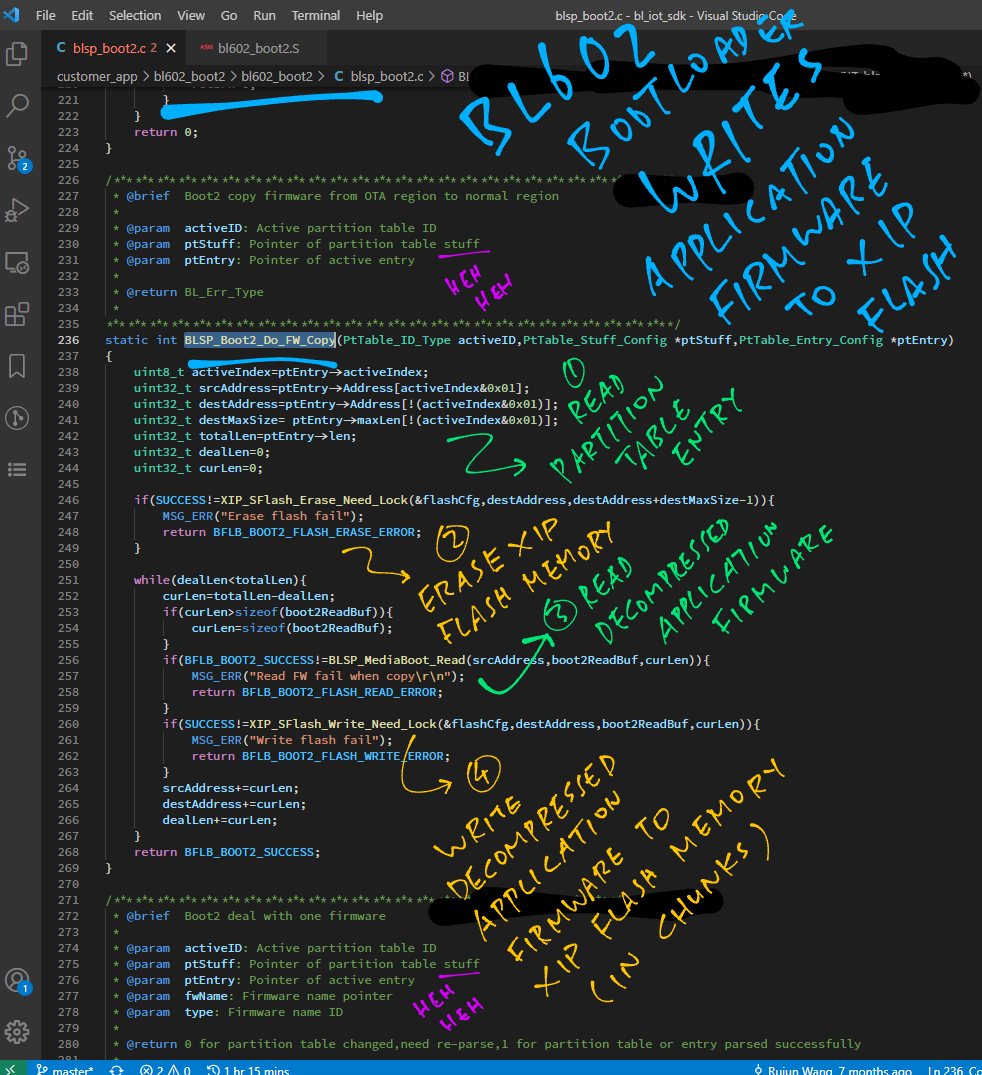
Previously on “Days Of Our Lives”… The Bootloader decompresses the Application Firmware and calls BLSP_Boot2_Do_FW_Copy to write the firmware to XIP Flash Memory.
Watch what happens next: blsp_boot2.c
//  Buffer for writing to XIP Flash Memory
#define BFLB_BOOT2_READBUF_SIZE  4 * 1024
uint8_t boot2ReadBuf[BFLB_BOOT2_READBUF_SIZE] __attribute__((section(".system_ram")));

//  Boot2 copy firmware from OTA region to normal region
static int BLSP_Boot2_Do_FW_Copy(
  PtTable_ID_Type activeID,         //  Active partition table ID
  PtTable_Stuff_Config *ptStuff,    //  Pointer of partition table stuff
  PtTable_Entry_Config *ptEntry) {  //  Pointer of active entry

  uint8_t activeIndex = ptEntry->activeIndex;
  uint32_t srcAddress = ptEntry->Address[activeIndex&0x01];
  uint32_t destAddress = ptEntry->Address[!(activeIndex&0x01)];
  uint32_t destMaxSize = ptEntry->maxLen[!(activeIndex&0x01)];
  uint32_t totalLen = ptEntry->len;
  uint32_t dealLen = 0;
  uint32_t curLen = 0;
BLSP_Boot2_Do_FW_Copy starts by fetching the Partition Table Entry for the Application Firmware, containing Source Address, Destination Address and Firmware Length.
(More about the Partition Table in the next chapter)
Then it erases the XIP Flash Memory at the Destination Address…
  if (SUCCESS != XIP_SFlash_Erase_Need_Lock(
    &flashCfg,
    destAddress,
    destAddress+destMaxSize - 1)) {
    MSG_ERR("Erase flash fail");
    return BFLB_BOOT2_FLASH_ERASE_ERROR;
  }
Next we handle the decompressed Application Firmware, chunk by chunk (4 KB)
  while (dealLen < totalLen) {
    curLen = totalLen - dealLen;
    if (curLen > sizeof(boot2ReadBuf)) {
      curLen = sizeof(boot2ReadBuf);
    }
We read the decompressed Application Firmware (in 4 KB chunks)
    if (BFLB_BOOT2_SUCCESS != BLSP_MediaBoot_Read(
      srcAddress,
      boot2ReadBuf,
      curLen)) {
      MSG_ERR("Read FW fail when copy\r\n");
      return BFLB_BOOT2_FLASH_READ_ERROR;
    }
We write the firmware to XIP Flash Memory (in 4 KB chunks)
    if (SUCCESS != XIP_SFlash_Write_Need_Lock(
      &flashCfg,
      destAddress,
      boot2ReadBuf,
      curLen)) {
      MSG_ERR("Write flash fail");
      return BFLB_BOOT2_FLASH_WRITE_ERROR;
    }
Finally we repeat the steps with the next 4 KB chunk, until the entire decompressed Application Firmware is written to XIP Flash Memory…
    srcAddress += curLen;
    destAddress += curLen;
    dealLen += curLen;
  }
  return BFLB_BOOT2_SUCCESS;
}
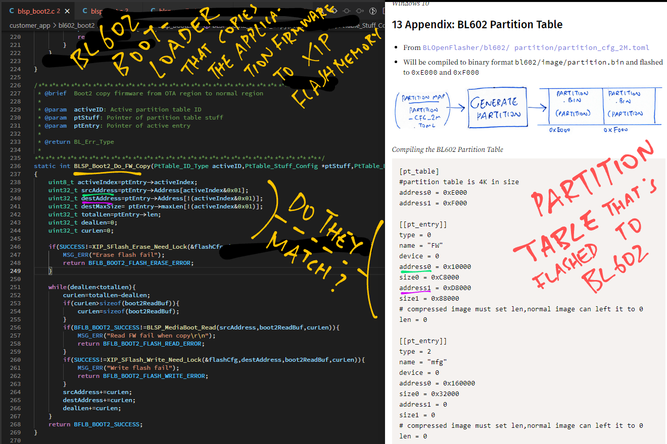
The Bootloader appears to be driven by the Partition Table (from the Flashing Image). What’s inside the Partition Table?
Each entry of the Partition Table describes a section of the Flashing Image.
Here’s the Partition Table Entry that describes our Application Firmware…
[[pt_entry]]
type     = 0
name     = "FW"
device   = 0
address0 = 0x10000
size0    = 0xC8000
address1 = 0xD8000
size1    = 0x88000
len      = 0
(From this BL602 Partition Table)
This Partition Table Entry says that our Application Firmware (compressed) is located in the Flash Image at offset 0x10000 with size 0xC8000 (compressed).
(But why are there two firmware sections 0x10000 and 0xD8000?)
With this information, our Bootloader will be able to decompress the Application Firmware and write to XIP Flash Memory…
static int BLSP_Boot2_Do_FW_Copy( ... ) {
  //  Fetch the Partition Table Entry for the Application Firmware
  uint8_t activeIndex = ptEntry->activeIndex;
  uint32_t srcAddress = ptEntry->Address[activeIndex&0x01];
  uint32_t destAddress = ptEntry->Address[!(activeIndex&0x01)];
  uint32_t destMaxSize = ptEntry->maxLen[!(activeIndex&0x01)];
  uint32_t totalLen = ptEntry->len;
(We’ve seen this earlier in blsp_boot2.c)
Exercise for the Reader: Please take these two things…
pt_entry Partition Table Entry above
BLSP_Boot2_Do_FW_Copy code above
Match them and verify that the code makes sense!
(Maybe we’ll figure out why there are two firmware sections 0x10000 and 0xD8000)
More about BL602 Partition Table
Earlier we’ve seen these functions called by the Bootloader to access XIP Flash Memory…
XIP_SFlash_Erase_Need_Lock: Erase XIP Flash Memory
XIP_SFlash_Read_Via_Cache_Need_Lock: Read XIP Flash Memory
XIP_SFlash_Write_Need_Lock: Write XIP Flash Memory
These XIP Flash Memory Functions are defined in the Bootloader right?
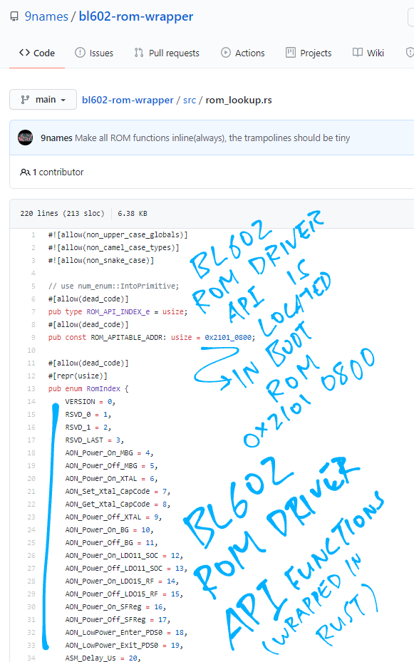
Not quite… The XIP Flash Memory Functions are located in the BL602 Boot ROM!
Shiver me timbers and call me Shirley! What’s the BL602 Boot ROM?
BL602 Boot ROM is the region of Read-Only Memory at 0x2100 0000 that contains…
Boot Code that’s run whenever we power on (or reset) BL602
(The Boot Code runs just before the Bootloader)
ROM Driver API called by the Bootloader
(Like the XIP Flash Memory Functions above)
Why put the ROM Driver API in the Boot ROM?
We reduce the Bootloader size by placing the low-level functions in Boot ROM
Some ROM Driver Functions need to run in a secure, tamper-proof ROM environment
(Like the functions for decrypting and verifying Application Firmware)
Wait this sounds familiar…?
Our computers have a similar Boot ROM… It’s called the Unified Extensible Firmware Interface (UEFI)
It contains secure boot code that’s run whenever we power on our computer.
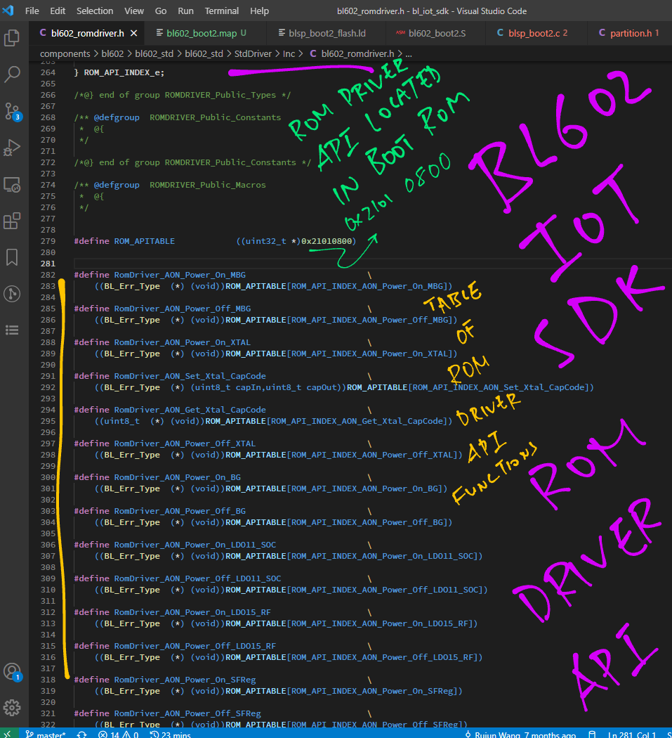
In the next chapter we shall explore the Table of ROM Driver API Functions located in ROM API at 0x2101 0800
From bl602_romdriver.h …
How did we find out that the ROM Driver API is located in Boot ROM?
Let’s look at the RISC-V Disassembly for the Bootloader: bl602_boot2.S
__ALWAYS_INLINE BL_Err_Type ATTR_TCM_SECTION
XIP_SFlash_Read_Via_Cache_Need_Lock(
  uint32_t addr,
  uint8_t *data,
  uint32_t len) {
  return RomDriver_XIP_SFlash_Read_Via_Cache_Need_Lock(
    addr,
    data,
    len);
}
That’s the C definition of the function XIP_SFlash_Read_Via_Cache_Need_Lock.
(Which is called by the Bootloader to read XIP Flash Memory)
The function looks kinda empty?
Yes, because XIP_SFlash_Read_Via_Cache_Need_Lock is a Stub Function.
It forwards the Function Call to the _Real Function: RomDriver_XIP_SFlash_Read_Via_Cache Need_Lock.
Where is the Real Function for reading XIP Flash Memory?
After the code above we see the RISC-V Assembly Code that the GCC Compiler has emitted for our Stub Function…
2201050a <XIP_SFlash_Read_Via_Cache_Need_Lock>:
2201050a:	210117b7          	lui	a5,0x21011
2201050e:	aa47a303          	lw	t1,-1372(a5) # 21010aa4 <StackSize+0x210106a4>
22010512:	8302                jr	t1
So the Real Function is located at 0x2101 0aa4?
Right! _RomDriver_XIP_SFlash_Read_Via_Cache Need_Lock is located in the Boot ROM at 0x2101 0aa4.
(Remember that the Boot ROM lives at 0x2100 0000 to 0x2101 FFFF)
Hence when the Bootloader reads XIP Flash Memory…
Bootloader calls the Stub Function at 0x2201 050a
(Located in ITCM)
Stub Function calls the Real Function at 0x2101 0aa4
(Located in Boot ROM)
What’s ITCM?
ITCM means Instruction Tightly Coupled Memory.
This is Cache Memory (RAM) that has been configured (via the Level 1 Cache Controller) for code execution.
(See “Chapter 7: L1C (Level 1 Cache)” in the BL602 Reference Manual)
What are the functions in the ROM Driver API?
The ROM Driver Functions are listed in bl602_romdriver.c and bl602_romdriver.h
The functions cover…
Power On / Off, Power Management, Reset
Memory Access, Flash Memory
GPIO, EFuse and Delay
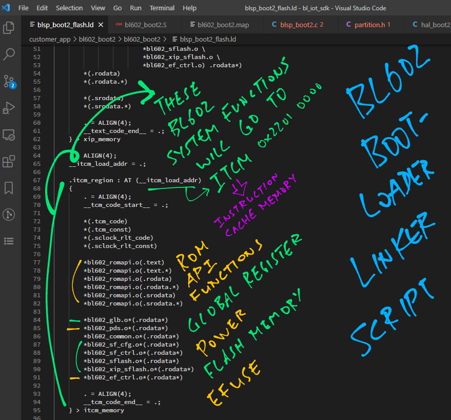
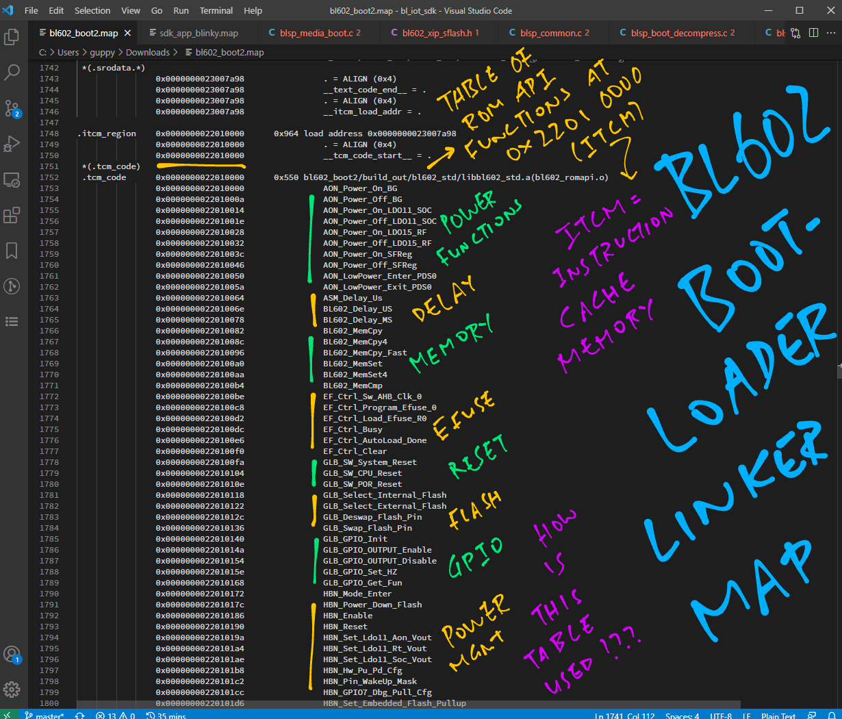
The Bootloader Linker Map bl602_boot2.map reveals the Table of ROM Driver Stub Functions at ITCM address 0x2201 0000…
Earlier we’ve seen the Bootloader calling BLSP_MediaBoot_Main to start our Application Firmware.
Let’s look inside the function: blsp_media_boot.c
 //  Media boot main process
int32_t BLSP_MediaBoot_Main(
  uint32_t cpuBootheaderAddr[BFLB_BOOT2_CPU_MAX],  //  CPU bootheader address list
  uint8_t cpuRollBack[BFLB_BOOT2_CPU_MAX],         //  CPU need roll back flag hold list
  uint8_t rollBack) {  //  1 for rollback when imge error occurs, 0 for not rollback when imge error occurs

  //  Omitted: Reset some parameters
  ...
  //  Omitted: Try to boot from flash
  ret = BLSP_MediaBoot_Parse_One_FW(
    &bootImgCfg[i],
    bootHeaderAddr[i],
    bootHeaderAddr[i] + BFLB_FW_IMG_OFFSET_AFTER_HEADER);
  ...
  //  Omitted: Get MSP and PC value
  ...
  //  Fix invalid PC and MSP
  BLSP_Fix_Invalid_MSP_PC();

  //  Prepare jump to entry
  BLSP_MediaBoot_Pre_Jump();

  //  We should never get here unless something is wrong
  return BFLB_BOOT2_FAIL;
}
This code calls BLSP_MediaBoot_Pre_Jump to start the firmware.
Let’s trace it: blsp_common.c
//  Media boot pre-jump
int32_t BLSP_MediaBoot_Pre_Jump(void) {
  //  Security Engine deinit
  BLSP_Boot2_Reset_Sec_Eng();

  //  Platform deinit
  bflb_platform_deinit();

  //  Jump to entry point
  BLSP_Boot2_Jump_Entry();
  return BFLB_BOOT2_SUCCESS;
}
Here we clean up the Security Engine and the Hardware Platform after use.
Then we call BLSP_Boot2_Jump_Entry to jump to the Application Firmware.
Let’s probe deeper: blsp_common.c
//  Boot2 jump to entryPoint
void ATTR_TCM_SECTION BLSP_Boot2_Jump_Entry(void) {
  ...
  BLSP_Sboot_Finish();

  //  Enable cache with flash offset.
  //  Note: After this, should be no flash direct read,
  //  If need to read, should take flash offset into consideration
  if (0 != efuseCfg.encrypted[0]) {
    //  For encrypted img, use non-continuous read
    ret = BLSP_Boot2_Set_Cache(
      0,
      &flashCfg,
      &bootImgCfg[0]);
  } else {
    //  For unencrypted img, use continuous read
    ret = BLSP_Boot2_Set_Cache(
      1,
      &flashCfg,
      &bootImgCfg[0]);
  }
  //  Omitted: Set decryption before reading MSP and PC
  if (0 != efuseCfg.encrypted[0]) {
    BLSP_Boot2_Set_Encrypt(0, &bootImgCfg[0]);
    BLSP_Boot2_Set_Encrypt(1, &bootImgCfg[1]);
    ...
  }
  //  Omitted: Handle Other CPU's entry point
  ...
  //  Handle CPU0's entry point
  if (bootImgCfg[0].imgValid) {
    pentry = (pentry_t) bootImgCfg[0].entryPoint;
    if (bootImgCfg[0].mspVal != 0) {
      __set_MSP(bootImgCfg[0].mspVal);
    }
    ...
    //  Jump to the entry point
    if (pentry != NULL) { pentry(); }
  }
As expected, the function ends by jumping to the Entry Point of our Application Firmware: pentry
But before that, it calls BLSP_Boot2_Set_Cache to fix up the XIP Flash Memory.
Let’s find out why.
Remember that the Bootloader and Application Firmware are both programmed to run at the same XIP Flash Memory address 0x2300 0000.
Does the Bootloader overwrite itself with the Application Firmware?
Not quite! Here’s the answer, many thanks to 9names on Twitter…
“It doesn’t overwrite itself, that’s the trick. What is at
0x23000000depends on how the cache is configured, you can change it!”
“See
BLSP_Boot2_Jump_Entryinblsp_common.cfor an example. This is what makes it possible to boot multiple applications without patching the firmware”
We’ve seen BLSP_Boot2_Jump_Entry in the previous chapter: blsp_common.c
//  Boot2 jump to entryPoint
void ATTR_TCM_SECTION BLSP_Boot2_Jump_Entry(void) {
  ...
  //  Enable cache with flash offset.
  //  Note: After this, should be no flash direct read,
  //  If need to read, should take flash offset into consideration
  //  For unencrypted img, use continuous read
  ret = BLSP_Boot2_Set_Cache(
    1,
    &flashCfg,
    &bootImgCfg[0]);
This code calls BLSP_Boot2_Set_Cache to fix up the cache for XIP Flash Memory: blsp_port.c
//  Media boot set cache according to image config
int32_t ATTR_TCM_SECTION BLSP_Boot2_Set_Cache(
  uint8_t contRead,
SPI_Flash_Cfg_Type *flashCfg,
    Boot_Image_Config *bootImgCfg) {
  ...
  //  If flash caching is enabled...
  if (bootImgCfg[0].cacheEnable) {

    //  And the Entry Point is in XIP Flash Memort 0x2300 0000...
    if ((bootImgCfg[0].entryPoint & 0xFF000000) == BLSP_BOOT2_XIP_BASE) {

      //  Set the flash image offset
      SF_Ctrl_Set_Flash_Image_Offset(
        bootImgCfg[0].imgStart.flashOffset);

      //  Enable reading of flash cache
      SFlash_Cache_Read_Enable(
        flashCfg,
        SF_CTRL_QIO_MODE,
        contRead,
        bootImgCfg[0].
        cacheWayDisable);
When we match this code with this Flashing Image Configuration, we get…
cacheEnable is true
entryPoint is BLSP_BOOT2_XIP_BASE (0x2300 0000)
imgStart is 0x2000
The calls to SF_Ctrl_Set_Flash_Image_Offset and SFlash_Cache_Read_Enable will remap the XIP Cache.
After remapping the XIP Cache, 0x2300 0000 will point to our Application Firmware. (Instead of the Bootloader)
And that’s how we switch over from Bootloader to Application Firmware in XIP Flash Memory!
(Note that SF_Ctrl_Set_Flash_Image_Offset and SFlash_Cache_Read_Enable are defined in the Boot ROM and we can’t see the source code. So it’s possible that our interpretation is incorrect)
What’s an EFuse in BL602?
An EFuse stores one bit of data (0 or 1) in a special way… Once an EFuse is set to 1, it can never be reset to 0.
BL602 has 1,024 EFuses (1,024 bits).
How are EFuses used in BL602?
Since the EFuses are one-time write-only bits, they are useful for storing AES Encryption Keys securely.
Once the AES Encryption Keys have been injected into BL602’s EFuses, they can never be changed.
Why would we need AES Encryption Keys in BL602?
BL602 Bootloader supports flashing of AES-Encrypted Application Firmware
(So it’s possible to push encrypted firmware updates over-the-air)
BL602 Bootloader can use Digital Signatures to verify that the Application Firmware is authentic
(Prevents tampering of firmware updates)
We don’t encrypt and sign firmware images during development.
But let’s watch how the BL602 Bootloader handles encrypted and signed firmware images for commercial BL602 gadgets.
How does the Bootloader work with the EFuse Hardware?
Earlier we saw the Bootloader calling BLSP_Boot2_Get_Efuse_Cfg to read the EFuse Configuration.
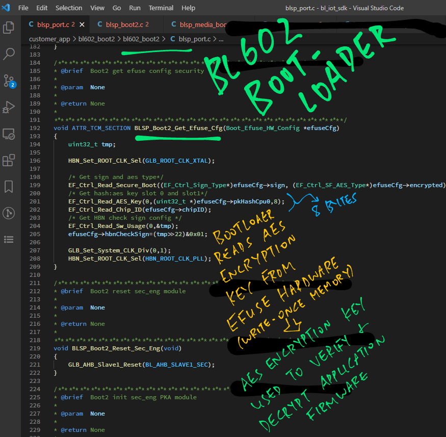
Here’s what happens inside: blsp_port.c
//  Boot2 get efuse config security
void ATTR_TCM_SECTION BLSP_Boot2_Get_Efuse_Cfg(
  Boot_Efuse_HW_Config *efuseCfg) {
  uint32_t tmp;

  HBN_Set_ROOT_CLK_Sel(GLB_ROOT_CLK_XTAL);

  //  Get sign and AES type
  EF_Ctrl_Read_Secure_Boot(
    (EF_Ctrl_Sign_Type*) efuseCfg->sign,
    (EF_Ctrl_SF_AES_Type*) efuseCfg->encrypted);

  //  Get hash: AES key slot 0 and slot 1
  EF_Ctrl_Read_AES_Key(
    0,
    (uint32_t *) efuseCfg->pkHashCpu0,
    8);
  EF_Ctrl_Read_Chip_ID(efuseCfg->chipID);

  //  Get HBN check sign config
  EF_Ctrl_Read_Sw_Usage(0, &tmp);
  efuseCfg->hbnCheckSign = (tmp >> 22) & 0x01;

  GLB_Set_System_CLK_Div(0, 1);
  HBN_Set_ROOT_CLK_Sel(HBN_ROOT_CLK_PLL);
}
This code calls the EF_Ctrl Functions from the BL602 Standard Driver to access the EFuse Hardware.
We decrypt the firmware with the EFuse Key here: blsp_port.c
//  Set encryption config
int32_t ATTR_TCM_SECTION BLSP_Boot2_Set_Encrypt(
  uint8_t index,                    //  Region index
  Boot_Image_Config *bootImgCfg) {  //  Boot image config pointer to hold parsed information
  ...
  //  Set AES Key
  SF_Ctrl_AES_Set_Key_BE(
      index,
      NULL,
      (SF_Ctrl_AES_Key_Type) (bootImgCfg->encryptType - 1));

  //  Set AES Initialisation Vector
  SF_Ctrl_AES_Set_IV_BE(
      index,
      bootImgCfg->aesiv,
      bootImgCfg->imgStart.flashOffset);

  //  Set AES Region
  SF_Ctrl_AES_Set_Region(
      index,
      1,  //  Enable this region
      1,  //  Hardware key
      bootImgCfg->imgStart.flashOffset,
      bootImgCfg->imgStart.flashOffset + len - 1,
      bootImgCfg->aesRegionLock);

  //  Enable AES decryption
  SF_Ctrl_AES_Enable_BE();
SF_Ctrl_AES_Enable();Today we looked at the Boot Code in the BL602 Bootloader and BL602 Boot ROM…
We’ve seen all the BL602 Boot Code right?
Wait… There’s more!
Our BL602 Application Firmware includes these functions from the BL602 Boot2 Hardware Abstraction Layer…
This is revealed by the Linker Map for our Blinky Firmware: sdk_app_blinky.map
(We might talk about these functions in a future article… Lemme know if you’re keen!)
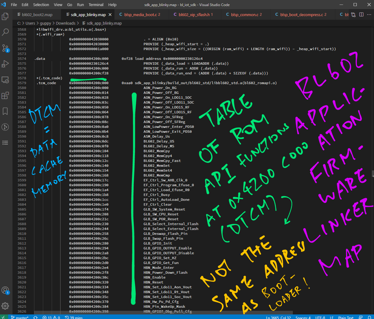
Remember Table of ROM Driver Stub Functions loaded by the Bootloader into ITCM (Instruction Cache Memory)?
Our Application Firmware has a similar Table of ROM Driver Stub Functions. But it’s loaded into DTCM (Data Cache Memory) instead…
How does BL602 Bootloader compare with other Bootloaders?
ESP32 Secure Boot V2
Similar to BL602, ESP32 supports XIP Flash Memory and EFuse Protection.
Hence the Bootloaders for ESP32 and BL602 probably work the same way.
RP2040
RP2040 also supports XIP Flash Memory in its Hardware Flash API (hardware_flash)
RP2040 has a Second Stage Bootloader (boot_stage2) that probably works like the BL602 Bootloader.
Remember the Boot ROM in BL602? RP2040 provides an API (pico_bootrom) to access functions and data in the Boot ROM.
PineTime Smart Watch (Nordic nRF52832)
PineTime doesn’t have XIP Flash Memory. But it has Internal Flash Memory (inside the microcontroller).
During startup, PineTime’s MCUBoot Bootloader installs new firmware by swapping in the firmware from External Flash Memory to Internal Flash Memory.
Similar to BL602 Bootloader, PineTime’s Bootloader supports Firmware Rollback. If the new firmware fails to start, PineTime swaps in the old firmware from External Flash Memory.
Check out this interview that explains the design rationale for the PineTime Bootloader…
Thanks for bearing with me as I attempted to unravel the secrets inside the BL602 Bootloader.
(This is my 20th article on BL602 yay! 🎉)
For my 21st article I shall explore Machine Learning with TensorFlow Lite on BL602…
“Machine Learning on RISC-V BL602 with TensorFlow Lite”
Stay Tuned!
Got a question, comment or suggestion? Create an Issue or submit a Pull Request here…
This article is the expanded version of this Twitter Thread
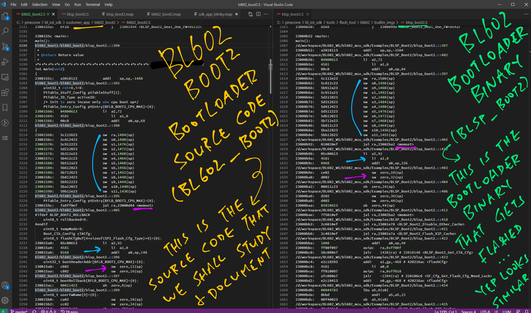
We have been studying the Bootloader Source Code for bl602_boot2… But the Bootloader Binary that’s actually flashed is blsp_boot2. How do we know that are the same?
We don’t have the source code for blsp_boot2. But we were able to disassemble blsp_boot2 and verify that it contains the same code as bl602_boot2.
Compare bl602_boot2.S with blsp_boot2.S …
9names has created Rust Wrappers for the BL602 ROM Driver API…