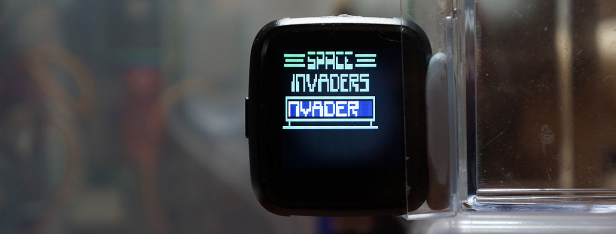
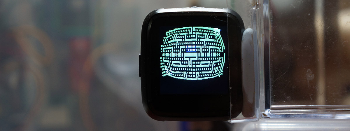
Space Invaders running on CHIP-8 Emulator on PineTime Smart Watch
📝 5 Mar 2020
Running Retro Games with Rust is not that hard on PineTime Smart Watch. Here's how I ported a CHIP-8 Game Emulator to PineTime...
Are you keen to use a Retro Game as a PineTime Watch Face? Lemme know!
We're using the libchip8 CHIP-8 Emulator for Rust. To start the emulator, we load the ROM file for the CHIP-8 game into memory, and call the Emulator to start the game...
///  Run the emulator
extern "C" fn task_func(_arg: Ptr) {
    //  Create the hardware API for rendering the emulator
    let hardware = Hardware::new();

    //  Create the emulator
    let chip8 = libchip8::Chip8::new(hardware);

    //  Load the emulator ROM
    let rom = include_bytes!("../roms/blinky.ch8");

    //  Run the emulator ROM. This will block until emulator terminates
    chip8.run(rom);

    //  Should not come here
    assert!(false, "CHIP8 should not end");
}
From https://github.com/lupyuen/pinetime-rust-mynewt/blob/master/rust/app/src/chip8.rs#L78-L98
Note the neat syntax used in Rust to load binary files into memory...
    //  Load the emulator ROM
    let rom = include_bytes!("../roms/blinky.ch8");
blinky.ch8 is a binary file that contains the program and data for the Blinky CHIP-8 game. By calling the include_bytes! macro, we load the entire binary file into memory as a Rust static memory object.
Here's a list of available CHIP-8 ROM files that we may download into the rust/app/roms folder
To preview the CHIP-8 games in a web browser, use this browser-based CHIP-8 Emulator.
How is Hardware used? We'll find out next...
Blinky running on CHIP-8 Emulator on PineTime Smart Watch
libchip8 is a clever CHIP-8 Emulator that supports all kinds of platforms, including Windows. How does it do that?
libchip8 abstracts all platform-specific operations (like Screen Updates) into the Hardware trait. Here's how we implement the Hardware trait on PineTime to set a screen pixel on or off...
impl libchip8::Hardware for Hardware {
    /// Set the color of a pixel in the screen. true for white, and false for black.
    fn vram_set(&mut self, x: usize, y: usize, color: bool) {
        assert!(x < SCREEN_WIDTH,  "x overflow");  //  x must be 0 to 63
        assert!(y < SCREEN_HEIGHT, "y overflow");  //  y must be 0 to 31
        let i = x + y * SCREEN_WIDTH;              //  index into screen buffer
        unsafe { SCREEN_BUFFER[i] =  //  Screen the screen buffer to...
            if color { 255 }         //  White pixel
            else     {   0 }         //  Black pixel
        };
        //  Remember the boundary of the screen region to be updated
        if self.update_left == 0 && self.update_right == 0 &&
            self.update_top == 0 && self.update_bottom == 0 {
            self.update_left = x as u8; self.update_right  = x as u8;
            self.update_top  = y as u8; self.update_bottom = y as u8;
        }
        //  If this pixel is outside the the boundary of the screen region to be updated, extend the boundary
        if (x as u8) < self.update_left   { self.update_left = x as u8;   }
        if (x as u8) > self.update_right  { self.update_right = x as u8;  }
        if (y as u8) < self.update_top    { self.update_top = y as u8;    }
        if (y as u8) > self.update_bottom { self.update_bottom = y as u8; }
    }
From https://github.com/lupyuen/pinetime-rust-mynewt/blob/master/rust/app/src/chip8.rs#L169-L198
(u8 means unsigned byte; usize is similar to size_t in C )
The CHIP-8 Emulator has a simple screen layout: 64 rows, 32 columns, 1-bit colour (black or white). vram_set updates the pixel colour in a greyscale memory buffer named SCREEN_BUFFER that's only 2 KB (64 rows of 32 bytes)...
/// CHIP8 Virtual Screen size, in Virtual Pixels
const SCREEN_WIDTH:  usize = 64;
const SCREEN_HEIGHT: usize = 32;
/// CHIP8 Virtual Screen Buffer, 8-bit greyscale (from black=0 to white=255) per Virtual Pixel.
/// The greyscale is mapped to 16-bit colour for display.
static mut SCREEN_BUFFER: [u8; SCREEN_WIDTH * SCREEN_HEIGHT] = [0; SCREEN_WIDTH * SCREEN_HEIGHT];  //  2 KB (64 rows of 32 bytes), u8 means unsigned byte
From https://github.com/lupyuen/pinetime-rust-mynewt/blob/master/rust/app/src/chip8.rs#L19-L37
Why did we allocate 8 bits per pixel in SCREEN_BUFFER?
So that we can implement interesting colour effects. (We'll cover this later) We actually update SCREEN_BUFFER with a greyscale colour like this...
//  color is true when emulator draws a white pixel, black otherwise
unsafe { SCREEN_BUFFER[i] =
    if color {
        if self.is_interactive { 255 }  //  Brighter colour when emulator is active
        else { 200 }                    //  Darker colour for initial screen
    }
    else {
        if self.is_interactive { 127 }  //  Fade to black
        else { 0 }                      //  Black for initial screen
    }
};
From https://github.com/lupyuen/pinetime-rust-mynewt/blob/master/rust/app/src/chip8.rs#L169-L198
Something seems to be missing... vram_set updates a screen buffer in memory... But we haven't actually updated the PineTime display!
vram_set is called every time the Emulator paints a pixel. Instead of refreshing the PineTime display pixel by pixel, we update the display by Sprite instead.
What's a Sprite?
No not the lemon-lime drink... It's the graphic that moves around in a game. In the Blinky / Pac-Man game, Pac-Man and the Ghosts are rendered as Sprites.
How do we know when a Sprite has been drawn?
We detect that in the sched function, where we update the PineTime display too.
How does CHIP-8 run game programs and render Sprites?
Think of CHIP-8 as an old-style home computer from the 1980s. It executes simple 8-bit Instructions (Opcodes), reading and writing data to CPU registers and RAM.
CHIP-8 has a unique Instruction that's not found in computers from the 1980s... An Instruction that renders Sprites. Since CHIP-8 renders Sprites as an CHIP-8 Instruction, we should update the PineTime screen only when the CHIP-8 Instruction has completed.
The CHIP-8 Emulator provides a convenient hook for that... It calls sched after executing every CHIP-8 Instruction...
impl libchip8::Hardware for Hardware {
    /// Called in every step; return true for shutdown.
    fn sched(&mut self) -> bool {
        //  If no screen update, return
        if self.update_left == 0 && self.update_right == 0 &&
            self.update_top == 0 && self.update_bottom == 0 { return false; }

        //  If emulator is preparing the initial screen, refresh the screen later
        if !self.is_interactive { return false; }

        //  If emulator is not ready to accept input, refresh the screen later
        if !self.is_checking_input { return false; }
        self.is_checking_input = false;

        //  Tickle the watchdog so that the Watchdog Timer doesn't expire. Mynewt assumes the process is hung if we don't tickle the watchdog.
        unsafe { hal_watchdog_tickle() };

        //  Sleep a while to allow other tasks to run, e.g. SPI background task
        unsafe { os::os_time_delay(1) };

        //  Render the updated region
        render_region(
            self.update_left,
            self.update_top,
            self.update_right,
            self.update_bottom
        );

        //  Reset the screen region to be updated
        self.update_left   = 0;
        self.update_top    = 0;
        self.update_right  = 0;
        self.update_bottom = 0;

        //  Return false to indicate no shutdown
        false
    }
From https://github.com/lupyuen/pinetime-rust-mynewt/blob/master/rust/app/src/chip8.rs#L231-L268
Instead of updating the entire PineTime display, we update only the rectangular portion that has been changed, by calling render_region.
(Recall that screen updates are tracked by vram_set)
Updating the PineTime display really slows down the CHIP-8 Emulator, so we defer all display updates until absolutely necessary.
When is it absolutely necessary to update the PineTime display?
That's when the game has rendered something and is checking whether the player has pressed any buttons
Thus we have these conditions to defer the PineTime display updates in sched...
//  If emulator is preparing the initial screen, refresh the screen later
if !self.is_interactive { return false; }

//  If emulator is not ready to accept input, refresh the screen later
if !self.is_checking_input { return false; }
self.is_checking_input = false;
From https://github.com/lupyuen/pinetime-rust-mynewt/blob/master/rust/app/src/chip8.rs#L231-L268
is_interactive and is_checking_input are flags set in the key function, which is called whenever the CHIP-8 Emulator is checking for button presses.
These simple conditions for defering the PineTime rendering are extremely effective. They make the PineTime CHIP-8 Emulator refresh some screens quicker than other versions of the CHIP-8 Emulator.
(Compare the loading screen for Blinky on PineTime vs other platforms)
Previously in sched we have identified the rectangular region of the PineTime display to be updated. We could call render_block to render the entire region to the PineTime display in a single SPI operation like this...
/// Render the Virtual Screen region
fn render_region(left: u8, top: u8, right: u8, bottom: u8) {
    //  Get the physical bounding box width and height
    let physical_box    = get_bounding_box(left, top, right, bottom);  //  Returns (left,top,right,bottom)
    let physical_width  = (physical_box.2 - physical_box.0 + 1) as usize;
    let physical_height = (physical_box.3 - physical_box.1 + 1) as usize;
    //  If the update region is small, render with a single block
    if physical_width + physical_height <= (BLOCK_WIDTH * PIXEL_WIDTH) + (BLOCK_HEIGHT * PIXEL_HEIGHT) {  //  Will not overflow SPI buffer
        render_block(left, top, right, bottom);
    } else {
        ...
From https://github.com/lupyuen/pinetime-rust-mynewt/blob/master/rust/app/src/chip8.rs#L271-L304
...But it won't always work!
Our Rust display driver for PineTime has a buffer size of 8 KB.
Since one pixel on the PineTime display has 16-bit colour, that means we can (roughly) transmit at most 4,096 pixels in a single SPI operation.
If we need to update the entire CHIP-8 Emulator screen, how many pixels would we need to transmit?
/// CHIP8 Physical Screen size, in Physical Pixels
const PHYSICAL_WIDTH:  usize = 240;
const PHYSICAL_HEIGHT: usize = 200;

/// CHIP8 Virtual Screen size, in Virtual Pixels
const SCREEN_WIDTH:  usize = 64;
const SCREEN_HEIGHT: usize = 32;

/// CHIP8 Virtual Pixel size, in Physical Pixels
const PIXEL_WIDTH:  usize = 3;  //  One Virtual Pixel = 3 x 5 Physical Pixels
const PIXEL_HEIGHT: usize = 5;
From https://github.com/lupyuen/pinetime-rust-mynewt/blob/master/rust/app/src/chip8.rs#L19-L37
To update the entite CHIP-8 display, we would need to transmit 48,000 pixels over SPI (PHYSICAL_WIDTH * PHYSICAL_HEIGHT)... Waaaaay too many pixels!
Why so many pixels? Isn't the CHIP-8 screen size only 64 x 32? (SCREEN_WIDTH by SCREEN_HEIGHT)
Yeah but we need to stretch every CHIP-8 Virtual Pixel into 15 PineTime Physical Pixels to fill the PineTime display!
(That's 3 * 5... PIXEL_WIDTH * PIXEL_HEIGHT)
Unfortunately the PineTime display controller (ST7789) doesn't handle stretching, so we need to do the stretching ourselves.
(But fret not... There's something interesting we shall see later... We can do curved stretching! Just like making pizza or roti prata!)
Thus to prevent the SPI buffer from overflowing, we update the screen in blocks of 32 by 5 Virtual Pixels on CHIP-8... (Or 96 by 25 Physical Pixels on the PineTime display)
/// CHIP8 Virtual Block size. We render the CHIP8 Virtual Screen in blocks of Virtual Pixels, without overflowing the SPI buffer.
/// PendingDataSize in SPI is 8192. (BLOCK_WIDTH * PIXEL_WIDTH * BLOCK_HEIGHT * PIXEL_HEIGHT) * 2 must be less than PendingDataSize
const BLOCK_WIDTH:  usize = 32;
const BLOCK_HEIGHT: usize = 5;  //  Letter height
From https://github.com/lupyuen/pinetime-rust-mynewt/blob/master/rust/app/src/chip8.rs#L27-L33
(Hmmm there's something wrong with the math here...)
Here's how we break the rendering region into smaller blocks to be rendered by render_block...
/// Render the Virtual Screen region
fn render_region(left: u8, top: u8, right: u8, bottom: u8) {
    ...
    //  If the update region is small, render with a single block
    if physical_width + physical_height <= (BLOCK_WIDTH * PIXEL_WIDTH) + (BLOCK_HEIGHT * PIXEL_HEIGHT) {
        ...
    } else {
        //  If the update region is too big for a single block, break the region into blocks and render
        let mut x = left;
        let mut y = top;
        loop {
            let block_right  = (x + BLOCK_WIDTH as u8 - 1).min(right);
            let block_bottom = (y + BLOCK_HEIGHT as u8 - 1).min(bottom);

            let physical_box    = get_bounding_box(left, top, right, bottom);  //  Returns (left,top,right,bottom)
            let physical_width  = (physical_box.2 - physical_box.0 + 1) as usize;
            let physical_height = (physical_box.3 - physical_box.1 + 1) as usize;
            render_block(x, y,
                block_right,
                block_bottom
            );  //  Will not overflow SPI buffer
            x += BLOCK_WIDTH as u8;
            if x > right {
                x = left;
                y += BLOCK_HEIGHT as u8;
                if y > bottom { break; }
            }
        }
    }
}
From https://github.com/lupyuen/pinetime-rust-mynewt/blob/master/rust/app/src/chip8.rs#L271-L304
The function get_bounding_box(left, top, right, bottom) simply returns a Rust tuple (left, top, right, bottom) that may be accessed by using the .0, .1, .2 and .3 notation (shown above like physical_box.0).
get_bounding_box doesn't do much now... But it will become very interesting later when we stretch the CHIP-8 pixels in a curvy way.
(Oh yes I love Rust tuples! As much as roti prata!)
Now we're ready to render a block of CHIP-8 Virtual Pixels (that has been checked by render_region and won't overflow the SPI buffer)...
/// Render the Virtual Block
fn render_block(left: u8, top: u8, right: u8, bottom: u8) {
    //  Create an iterator for the Physical Pixels to be rendered
    let mut block = PixelIterator::new(
        left, top,
        right, bottom,
    );
    //  Get the Physical Pixel dimensions of the Virtual Pixels
    let (left_physical, top_physical, right_physical, bottom_physical) = block.get_window();
    //  Render the block via the iterator
    druid::set_display_pixels(left_physical as u16, top_physical as u16, right_physical as u16, bottom_physical as u16,
        &mut block
    ).expect("set pixels failed");
}
From https://github.com/lupyuen/pinetime-rust-mynewt/blob/master/rust/app/src/chip8.rs#L306-L319
Rendering a block of CHIP-8 Virtual Pixels looks suspiciously simple... What's an Iterator?
A Rust Iterator loops over individual values in a sequence of values. (It's often used in for loops)
Here we create a Rust Iterator that loops over individual Physical PineTime Pixels to be rendered (based on the Virtual CHIP-8 Block that's passed in).
The values returned by the Rust Iterator are 16-bit colour values. Our Rust display driver for PineTime calls the Rust Iterator to enumerate all the 16-bit colour values and blast all values in a single SPI operation. Super efficient!
Here's the implementation of our iterator that enumerates all Physical Pixel Colours within a Virtual Pixel Block that's defined by the Virtual (x, y) Coordinates from (block_left, block_top) to (block_right, block_bottom)...
/// Implement the Iterator for Virtual Pixels in a Virtual Block
impl Iterator for PixelIterator {
    /// This Iterator returns Physical Pixel colour words (16-bit)
    type Item = u16;

    /// Return the next Physical Pixel colour
    #[cfg(not(feature = "chip8_curve"))]  //  If we are not rendering CHIP8 Emulator as curved surface...
    fn next(&mut self) -> Option<Self::Item> {
        if self.y > self.block_bottom { return None; }  //  No more Physical Pixels

        //  Get the 16-bit Physical Colour for the Virtual Pixel at (x, y)
        let color = self.get_color();

        //  Update (x, y) to the next pixel left to right, then top to bottom...
        //  Loop over every stretched horizontal Physical Pixel (x_offset) from 0 to PIXEL_WIDTH - 1
        self.x_offset += 1;
        if self.x_offset >= PIXEL_WIDTH as u8 {
            self.x_offset = 0;

            //  Loop over every Virtual Pixel (x) from block_left to block_right
            self.x += 1;
            if self.x > self.block_right {
                self.x = self.block_left;

                //  Loop over every stretched vertical Vertical Pixel (y_offset) from 0 to PIXEL_HEIGHT - 1
                self.y_offset += 1;
                if self.y_offset >= PIXEL_HEIGHT as u8 {
                    self.y_offset = 0;

                    //  Loop over every Virtual Pixel (y) from block_top to block_bottom
                    self.y += 1;
                }
            }
        }
        //  Return the Physical Pixel color
        return Some(color);
    }
From https://github.com/lupyuen/pinetime-rust-mynewt/blob/master/rust/app/src/chip8.rs#L408-L455
The Iterator returns the next Physical Pixel Colour, as defined by self.x (Current Virtual Column) and self.y (Current Virtual Row).
Let's look at function get_color, which maps greyscale CHIP-8 Virtual Colours to 16-bit PineTime Physical Colours...
CHIP-8 doesn't support colour... Everything is rendered in black and white... Only Two Shades of Grey!
What if we spice up CHIP-8 games with a dash of colour? How shall we colourise a CHIP-8 game that doesn't know anything about colour?
By hooking on to the key function, we know when the game is first seeking input... Everything that the game renders after startup and up till the first call to key is most likely the Initial Loading Screen.
Thus in the key function we flag is_interactive as true at the first call to key.
impl libchip8::Hardware for Hardware {
    /// Check if the key is pressed.
    fn key(&mut self, key: u8) -> bool {
        //  key is 0-9 for keys "0" to "9", 0xa-0xf to keys "A" to "F"
        if !self.is_interactive {
            self.is_interactive = true;
        }
        self.is_checking_input = true;
        //  Compare the key with the last touch event
        if unsafe { KEY_PRESSED == Some(key) } {
            unsafe { KEY_PRESSED = None };  //  Clear the touch event
            return true;
        }
        false
    }
From https://github.com/lupyuen/pinetime-rust-mynewt/blob/master/rust/app/src/chip8.rs#L133-L147
Since we can identify the Initial Loading Screen... Let's colour that screen!
Remember this code from vram_set?
//  color is true when emulator draws a white pixel, black otherwise
unsafe { SCREEN_BUFFER[i] =
    if color {                          //  If emulator draws a white pixel...
        if self.is_interactive { 255 }  //  Brighter colour when emulator is active
        else { 200 }                    //  Darker colour for initial screen
    }
    else {                              //  If emulator draws a black pixel...
        ...
From https://github.com/lupyuen/pinetime-rust-mynewt/blob/master/rust/app/src/chip8.rs#L169-L198
Instead of plain black and white, our CHIP-8 Virtual Screen Buffer now stores 8-bit greyscale... 256 Shades of Grey!
Through the is_interactive flag, we may now paint the Initial Loading Screen as greyscale 200. Other pixels drawn after the Initial Loading Screen will be set to greyscale 255.
Greyscale 200 is converted into a greenish hue, while greyscale 255 is converted to bright white...
/// Convert the Virtual Colour (8-bit greyscale) to 16-bit Physical Pixel Colour
fn convert_color(grey: u8) -> u16 {
    match grey {
        250..=255 => Rgb565::from(( grey,       grey, grey )).0,        //  White
        128..250  => Rgb565::from(( grey - 100, grey, grey - 100 )).0,  //  Greenish
        0..128    => Rgb565::from(( 0,          0,    grey )).0,        //  Dark Blue
    }
}
From https://github.com/lupyuen/pinetime-rust-mynewt/blob/master/rust/app/src/chip8.rs#L494-L510
Note that 128..250 means 128 to 249, excluding 250. Whereas 250..=255 means 250 to 255 (inclusive)
The above function convert_color is called by get_color to map CHIP-8 Virtual Pixel Greyscale into 16-bit Physical Pixel Colour when rendering every pixel...
impl PixelIterator {
    /// Return the 16-bit colour of the Virtual Pixel
    fn get_color(&mut self) -> u16 {
        //  Get the greyscale colour at Virtual Coordinates (x,y) and convert to 16-bit Physical Colour
        let i = self.x as usize + self.y as usize * SCREEN_WIDTH;
        let color = unsafe { convert_color( SCREEN_BUFFER[i] ) };
        //  Update the greyscale colour at Virtual Coordinates (x,y)
        if self.x_offset == 0 && self.y_offset == 0 {  //  Update colours only once per Virtual Pixel
            unsafe { SCREEN_BUFFER[i] = update_color( SCREEN_BUFFER[i] ); }  //  e.g. fade to black
        }
        color  //  Return the 16-bit Physical Colour
    }
}
From https://github.com/lupyuen/pinetime-rust-mynewt/blob/master/rust/app/src/chip8.rs#L376-L385
Thus our Initial Loading Screen now looks green. Other Sprites in the game will appear as white (greyscale 255) because they are rendered after the game has started seeking button input.
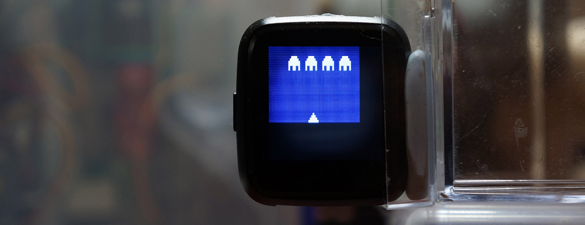
This colouring effect is most obvious in the Space Invaders title screen.
Space Invaders title screen in green
What about black pixels? Recall the code from vram_set...
//  color is true when emulator draws a white pixel, black otherwise
unsafe { SCREEN_BUFFER[i] =
    if color {                          //  If emulator draws a white pixel...
        ...
    }
    else {                              //  If emulator draws a black pixel...
        if self.is_interactive { 127 }  //  Fade to black
        else { 0 }                      //  Black for initial screen
    }
};
From https://github.com/lupyuen/pinetime-rust-mynewt/blob/master/rust/app/src/chip8.rs#L169-L198
Assuming that the game is actually running (after showing the Initial Loading Screen), is_interactive is flagged as true.
The above code sets the CHIP-8 Virtual Pixel to greyscale 127. Which is mapped by convert_color to a dark blue colour...
/// Convert the Virtual Colour (8-bit greyscale) to 16-bit Physical Pixel Colour
fn convert_color(grey: u8) -> u16 {
    match grey {
        250..=255 => Rgb565::from(( grey,       grey, grey )).0,        //  White
        128..250  => Rgb565::from(( grey - 100, grey, grey - 100 )).0,  //  Greenish
        0..128    => Rgb565::from(( 0,          0,    grey )).0,        //  Dark Blue
    }
}

/// Fade the Virtual Colour (8-bit greyscale) to black
fn update_color(grey: u8) -> u8 {
    match grey {
        200..=255 => grey - 2,    //  Initial white flash fade to normal white
        128..200  => grey,        //  Normal white stays the same
        0..128    => grey >> 1,   //  Dark fade to black
    }
}
From https://github.com/lupyuen/pinetime-rust-mynewt/blob/master/rust/app/src/chip8.rs#L494-L510
Note that the update_color function above is also called by get_color while rendering each pixel of the PineTime display.
update_color gradually diminishes greyscale 127 until it reaches 0, at every rendering of the pixel. (>>1 shifts the greyscale right by 1 bit, which is the same as dividing by 2)
The result: Black pixels appear as dark blue trails that fade to black.
This colouring effect is most obvious in the Pong game... Watch the trail of the bouncing ball.
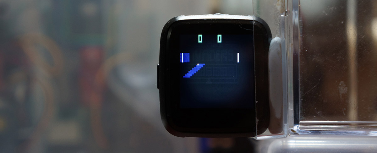
Pong ball trail in blue
CHIP-8 uses a keypad with 15 keys, marked 0 to 9, A to F.
For PineTime we'll emulate a simple keypad: Tapping the Left part of the touchscreen simulates the key 4, Centre part simulates 5, Right part simulates 6.
This is sufficient for playing Space Invaders, which uses 4 and 6 to move your spaceship Left and Right, and 5 to fire.
Function handle_touch is called by the PineTime Rust touch controller driver with the (x,y) coordinates of the touched point, from (0,0) to (239,239)...
/// Handle touch events to emulate buttons
pub fn handle_touch(x: u16, _y: u16) {
    //  We only handle 3 keys: 4, 5, 6, which correspond to Left, Centre, Right
    let key =                                                  //  PHYSICAL_WIDTH is 240
        if x < PHYSICAL_WIDTH as u16 / 3 { Some(4) }           //  Left = 4
        else if x < 2 * PHYSICAL_WIDTH as u16 / 3 { Some(5) }  //  Centre = 5
        else { Some(6) };                                      //  Right = 6
    unsafe { KEY_PRESSED = key };
}

/// Represents the key pressed: 0-9 for keys "0" to "9", 0xa-0xf to keys "A" to "F", None for nothing pressed
static mut KEY_PRESSED: Option<u8> = None;
From https://github.com/lupyuen/pinetime-rust-mynewt/blob/master/rust/app/src/chip8.rs#L133-L147
handle_touch stores the simulated keypress into KEY_PRESSED
Note that KEY_PRESSED has type Option<u8>, which is an optional unsigned byte. So KEY_PRESSED may contain a specified byte (like Some(4)), or nothing (None).
The CHIP-8 Emulator checks for keys pressed by calling the key function...
impl libchip8::Hardware for Hardware {
    /// Check if the key is pressed.
    fn key(&mut self, key: u8) -> bool {
        //  key is 0-9 for keys "0" to "9", 0xa-0xf to keys "A" to "F"
        if !self.is_interactive {
            self.is_interactive = true;
        }
        self.is_checking_input = true;
        //  Compare the key with the last touch event
        if unsafe { KEY_PRESSED == Some(key) } {
            unsafe { KEY_PRESSED = None };  //  Clear the touch event
            return true;
        }
        false
    }
From https://github.com/lupyuen/pinetime-rust-mynewt/blob/master/rust/app/src/chip8.rs#L492-L504
When the Emulator calls key(self, 4), we should return true if the key 4 has been pressed, i.e. KEY_PRESSED has value Some(4)
This doesn't found efficient for checking many keys... But it's probably OK for retro games.
Playing Space Invaders with 3 touch points: Left, Centre, Right
▶️ 抖音视频
The CHIP-8 Emulator blocks and doesn't return when we call its run function. PineTime needs multitasking to refresh the display (via SPI) and to accept touchscreen input, so we need to start a Background Task for the emulator...
/// Erase the PineTime display and start the CHIP-8 Emulator task
pub fn on_start() -> MynewtResult<()> {
    //  Create black background
    let background = Rectangle::<Rgb565>
        ::new( Coord::new( 0, 0 ), Coord::new( 239, 239 ) )   //  Rectangle coordinates
        .fill( Some( Rgb565::from(( 0x00, 0x00, 0x00 )) ) );  //  Black

    //  Render background to display
    druid::draw_to_display(background);

    //  Start the emulator in a background task
    os::task_init(                  //  Create a new task and start it...
        unsafe { &mut CHIP8_TASK }, //  Task object will be saved here
        &init_strn!( "chip8" ),     //  Name of task
        Some( task_func ),    //  Function to execute when task starts
        NULL,  //  Argument to be passed to above function
        20,    //  Task priority: highest is 0, lowest is 255 (main task is 127), SPI is 10
        os::OS_WAIT_FOREVER as u32,       //  Don't do sanity / watchdog checking
        unsafe { &mut CHIP8_TASK_STACK }, //  Stack space for the task
        CHIP8_TASK_STACK_SIZE as u16      //  Size of the stack (in 4-byte units)
    ) ? ;                                 //  `?` means check for error

    //  Return success to the caller
    Ok(())
}

/// CHIP8 Background Task
static mut CHIP8_TASK: os::os_task = fill_zero!(os::os_task);

/// Stack space for CHIP8 Task, initialised to 0.
static mut CHIP8_TASK_STACK: [os::os_stack_t; CHIP8_TASK_STACK_SIZE] =
    [0; CHIP8_TASK_STACK_SIZE];

/// Size of the stack (in 4-byte units). Previously `OS_STACK_ALIGN(256)`
const CHIP8_TASK_STACK_SIZE: usize = 4096;  //  Must be 4096 and above because CHIP8 Emulator requires substantial stack space
From https://github.com/lupyuen/pinetime-rust-mynewt/blob/master/rust/app/src/chip8.rs#L39-L66
Note that we're using Apache Mynewt OS to manage multitasking on PineTime, so we need to use the Mynewt functions (like task_init) for scheduling and synchronising our tasks.
To build the CHIP-8 Emulator for PineTime, edit the Rust configuration file rust/app/Cargo.toml.
Uncomment the feature chip8_app and comment out all other features, like this...
[features]
default =  [          # Select the conditional compiled features
    # "display_app",  # Disable graphics display app
    # "ui_app",       # Disable druid UI app
    # "visual_app",   # Disable Visual Rust app
    "chip8_app",      # Enable CHIP8 Emulator app
    # "chip8_curve",  # Uncomment to render CHIP8 Emulator as curved surface (requires chip8_app)
    # "use_float",    # Disable floating-point support e.g. GPS geolocation
]
From https://github.com/lupyuen/pinetime-rust-mynewt/blob/master/rust/app/Cargo.toml
If you're using the curved rendering feature (explained in the next section), uncomment both chip8_app and chip8_curve.
Edit the Mynewt configuration file apps/my_sensor_app/syscfg.yml.
Set OS_MAIN_STACK_SIZE to 2048...
syscfg.vals:
    # OS_MAIN_STACK_SIZE: 1024  #  Small stack size: 4 KB
    OS_MAIN_STACK_SIZE: 2048    #  Normal stack size: 8 KB
    # OS_MAIN_STACK_SIZE: 4096  #  Large stack size: 16 KB
From https://github.com/lupyuen/pinetime-rust-mynewt/blob/master/apps/my_sensor_app/syscfg.yml
This shrinks the default system stack size and allows us to allocate a larger stack that's needed for the emulator task.
Then build the PineTime firmware according to the instructions here.
Remember we said earlier that every Virtual Pixel on CHIP-8 is rendered as a rectangular chunk of 15 Physical Pixels on the PineTime display. (Because we need to stretch the pixel to fill the PineTime display)
Not super efficient... But since we're blasting out 15 pixels anyway... Can we be more creative? What if we blast the 15 pixels in a curvy way like this...
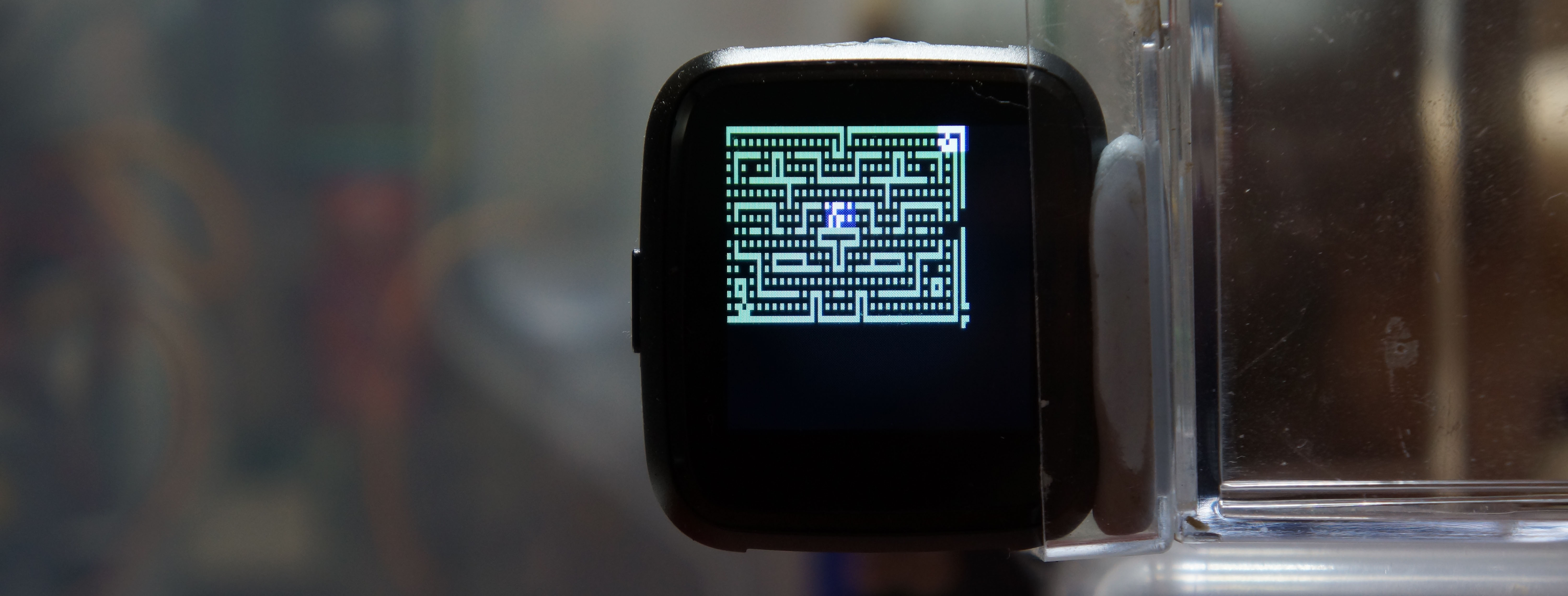
Blinky distorted on a curved surface
This looks interesting... Almost "Organic", like a CRT display protruding from the PineTime screen. So let's get adventurous!
How shall we distort the CHIP-8 Emulator in a curvy way based on this rectangular grid...
Blinky without distortion... See how the distorted version fills the entire display width nicely? That's the power of distortion!
Mathematically we are mapping a Square (the CHIP-8 output) to a Sphere (the curved rendering surface) like this...
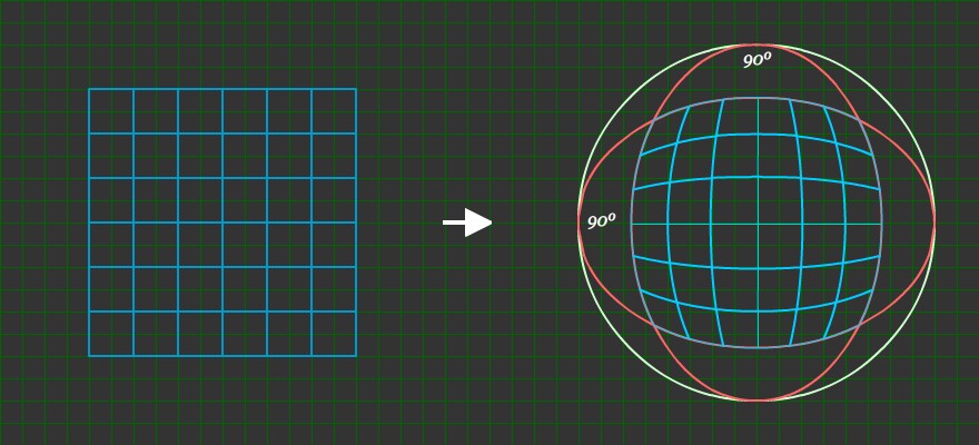
From https://stackoverflow.com/questions/18264703/mapping-a-2d-grid-onto-a-sphere
The obvious approach would be to crack open the Sine and Cosine Functions from our high school textbooks and work out the correct formula... But we shall do no such boring things here!
Let's look at 3D Interpolation instead. I have a strong hunch that...
Calling sin and cos at every pixel rendering would be too taxing on our nRF52 microcontroller
We have plenty of ROM on PineTime (512 KB). Perfect for our nRF52 microcontroller to look up simple Lookup Tables that will map Virtual Pixel to Physical Pixels and vice versa.
How will the Lookup Tables work? Given a Virtual Pixel on CHIP-8, we need to find out the corresponding Physical Pixels on the curvy PineTime display.
And the Lookup Tables will also tell us the Virtual Pixel that corresponds to each Physical Pixel. (This is a One Virtual Pixel to Multiple Physical Pixel mapping... Mathematically, 1:N)
The PineTime display is only 240x240... Precomputing and storing the Lookup Tables into ROM should be easy. Note that the mapping of Square to Sphere is Symmetric on the X and Y axes. So we only need to compute one quadrant of the mapping! (I chose the lower right quadrant)
To compute the Lookup Tables, we'll take a few points from the Square to Sphere mapping and interpolate them (i.e. run a Rust program to fill in the missing pixels between the points).
Interpolating the pixels is probably a good idea for the long term... It lets us tweak the mapping manually by shifting the points. (Instead of figuring out complicated math formulae)
How shall we get the Interpolation Points to map the rectangular Virtual Pixels on CHIP-8 to the curved Physical Pixels on PineTime display? Let's copy them literally from the Square to Sphere Interpolation Diagram!
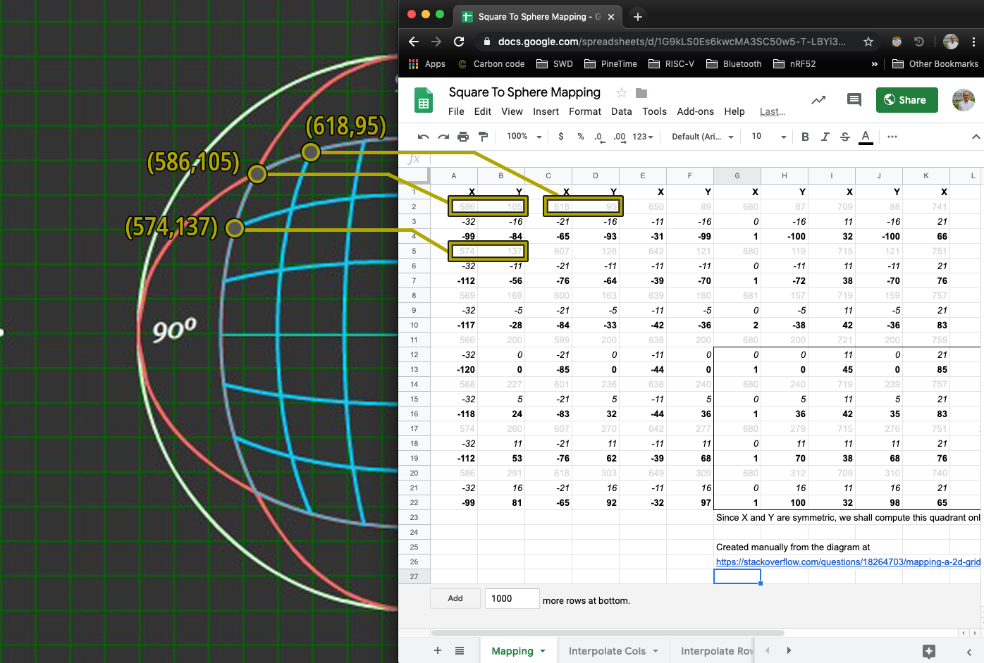
Interpolation Points copied from diagram into spreadsheet. From https://docs.google.com/spreadsheets/d/1G9kLS0Es6kwcMA3SC50w5-T-LBYi3NQeY98y7HOAovs/edit#gid=0
This produces 49 curved Intepolation Points (7 * 7) that we shall map into a rectangular grid for CHIP-8. As shown in the top left corner of the spreadsheet...
(586, 105) on the curved PineTime surface, normalised to (-99, -84), maps to normalised (-32, -16) on CHIP-8
(618, 95) on the curved PineTime surface, normalised to (-65, -93), maps to normalised (-21, -16) on CHIP-8
(574, 137) on the curved PineTime surface, normalised to (-112, -56), maps to normalised (-32, -11) on CHIP-8
We normalise Physical PineTime Pixels on the curved surface to fall within (-120, -100) to (120, 100)... And Virtual CHIP-8 Pixels within (-32, -16) to (32, 16)
But since X and Y are Symmetric in the mapping, we'll consider only the lower right quadrant of the spreadsheet...
Normalised (1, 0) on the curved PineTime surface maps to normalised (0, 0) on CHIP-8
Normalised (45, 0) on the curved PineTime surface maps to normalised (11, 0) on CHIP-8
Normalised (1, 36) on the curved PineTime surface maps to normalised (0, 5) on CHIP-8
We're now ready to interpolate the missing Physical and Virtual Pixels. We'll feed the above numbers to the [spade] crate for interpolation, in two steps.
We'll feed the numbers for PineTime Physical (X, Y) → CHIP-8 Virtual X first...
#[cfg(feature = "interpolate_x")]  //  If interpolating X values...
fn load_data() -> [Point3<f64>; 16] {
    [
        //  Generated by https://docs.google.com/spreadsheets/d/1G9kLS0Es6kwcMA3SC50w5-T-LBYi3NQeY98y7HOAovs/edit#gid=1875321785
        p( 1 as f64,  0 as f64,  0 as f64),  //  Physical ( 1,  0) → Virtual X =  0
        p(45 as f64,  0 as f64, 11 as f64),  //  Physical (45,  0) → Virtual X = 11
        p( 1 as f64, 36 as f64,  0 as f64),  //  Physical ( 1, 36) → Virtual X =  0
        ...
From https://github.com/lupyuen/interpolate-surface/blob/master/src/delaunay_creation.rs
Then PineTime Physical (X, Y) → CHIP-8 Virtual Y...
#[cfg(feature = "interpolate_y")]  //  If interpolating Y values...
fn load_data() -> [Point3<f64>; 16] {
    [
        //  Generated by https://docs.google.com/spreadsheets/d/1G9kLS0Es6kwcMA3SC50w5-T-LBYi3NQeY98y7HOAovs/edit#gid=1875321785
        p( 1 as f64,  0 as f64, 0 as f64),  //  Physical ( 1,  0) → Virtual Y = 0
        p(45 as f64,  0 as f64, 0 as f64),  //  Physical (45,  0) → Virtual Y = 0
        p( 1 as f64, 36 as f64, 5 as f64),  //  Physical ( 1, 36) → Virtual Y = 5
        ...
From https://github.com/lupyuen/interpolate-surface/blob/master/src/delaunay_creation.rs
We'll use Natural Neighbor 3D Interpolation from the [spade] crate to interpolate the missing Virtual (X, Y) pixels, in two steps (Virtual X then Virtual Y).
Why is this considered 3D Interpolation, not 2D Interpolation? Because we are mapping two numbers (Physical X = 1, Physical Y = 0) to a third number (Virtual X = 0)
It sounds like a miracle, but the [spade] 3D Interpolation Program will produce smoothly-interpolated CHIP-8 Virtual X values for every single PineTime pixel of Physical (X, Y) from (0, 0) to (120, 100)... (That's the lower right quadrant)
Physical ( 1,  0) -> Virtual X =  0  //  Provided value
Physical ( 2,  0) -> Virtual X =  0  //  Interpolated value
Physical ( 3,  0) -> Virtual X =  1  //  Interpolated value
...
Physical (45,  1) -> Virtual X = 11  //  Provided value
Physical (46,  1) -> Virtual X = 11  //  Interpolated value
Physical (47,  1) -> Virtual X = 11  //  Interpolated value
...
Physical ( 1, 36) -> Virtual X =  0  //  Provided value
Physical ( 2, 36) -> Virtual X =  0  //  Interpolated value
Physical ( 3, 36) -> Virtual X =  1  //  Interpolated value
...
Output of interpolate-surface program. From https://docs.google.com/spreadsheets/d/1G9kLS0Es6kwcMA3SC50w5-T-LBYi3NQeY98y7HOAovs/edit#gid=1436721555
The program will also produce smoothly-interpolated CHIP-8 Virtual Y values for every single PineTime pixel of Physical (X, Y) in the lower right quadrant. (Need to edit Cargo.toml and select the feature interpolate_y)
So mapping from every Physical Pixel on the curved PineTime display to Virtual Pixel on CHIP-8 is complete!
Now let's map every Virtual Pixel on CHIP-8 to Physical Pixels on the curved PineTime display.
Fortunately there's no need to use 3D Interpolation here... We'll simply search for all Physical Pixels that correspond to each Virtual Pixel, using the Physical → Virtual mapping that we have created earlier.
(Remember that Physical Pixels range from (0, 0) to (120, 100), so the search should be quite fast on a desktop computer)
Here's how we find all Physical Pixels that are mapped from each Virtual Pixel...
/// Given a grid of Physical (x,y) Coordinates and their interpolated Virtual (x,y) Coordinates,
/// find all Physical (x,y) Coordinates that interpolate to (x_virtual,y_virtual).
/// Return the (left, top, right, bottom) of the Bounding Box that encloses these found points.
/// x_virtual and y_virtual are truncated to integer during comparison.
/// Function returns `None` if (x_virtual,y_virtual) was not found.
fn get_bounding_box(
    x_virtual_grid: &[[f64; X_PHYSICAL_SUBDIVISIONS + 1]; Y_PHYSICAL_SUBDIVISIONS + 1],
    y_virtual_grid: &[[f64; X_PHYSICAL_SUBDIVISIONS + 1]; Y_PHYSICAL_SUBDIVISIONS + 1],
    x_virtual: f64,
    y_virtual: f64
) -> Option<(f64, f64, f64, f64)> {
    let mut left: f64 = f64::MAX;
    let mut top: f64 = f64::MAX;
    let mut right: f64 = f64::MIN;
    let mut bottom: f64 = f64::MIN;
    //  For all Physical (x,y) Coordinates...
    for y in 0..=Y_PHYSICAL_SUBDIVISIONS {
        for x in 0..=X_PHYSICAL_SUBDIVISIONS {
            //  Get the Physical (x,y) Coordinates
            let pos = transform_physical_point(cg::Point2::new(x as f64, y as f64));

            //  Get the interpolated Virtual (x,y) Coordinates
            let x_interpolated = x_virtual_grid[y][x].floor();
            let y_interpolated = y_virtual_grid[y][x].floor();

            //  Skip if not matching
            if x_interpolated as u8 != x_virtual as u8 ||
                y_interpolated as u8 != y_virtual as u8 { continue; }

            //  Find the Bounding Box of the Physical (x,y) Coordinates
            if pos.x < left   { left   = pos.x; }
            if pos.y < top    { top    = pos.y; }
            if pos.x > right  { right  = pos.x; }
            if pos.y > bottom { bottom = pos.y; }
        }
    };
    if left < f64::MAX && top < f64::MAX &&
        right > f64::MIN && bottom > f64::MIN {  //  (x_virtual,y_virtual) found
            Some((left.floor(), top.floor(), right.floor(), bottom.floor()))
    } else { None }  //  (x_virtual,y_virtual) not found
}
From https://github.com/lupyuen/interpolate-surface/blob/master/src/main.rs#L297-L337
Each CHIP-8 Virtual Pixel may map to one or more PineTime Physical Pixels. Instead of returning all matching Physical Pixels, we return the Physical Bounding Box instead... The Physical Bounding Box at Physical Coordinates (Left, Top) to (Right, Bottom) is the smallest box that contains all the matching Physical Pixels.
The above function get_bounding_box is called like this for every Virtual CHIP-8 Pixel...
/// For all Virtual (x,y) Coordinates, compute the Bounding Box that encloses the corresponding Physical (x,y) Coordinates.
/// Used by the CHIP-8 Emulator to decide which Physical Pixels to redraw when a Virtual Pixel is updated.
fn generate_virtual_to_physical_map() {
    println!("VIRTUAL_TO_PHYSICAL_MAP=");
    print!("[");
    for y in 0..Y_VIRTUAL_SUBDIVISIONS {
        print!("[");
        for x in 0..X_VIRTUAL_SUBDIVISIONS {
            //  Convert the normalised (x,y) into Virtual (x,y) Coordinates
            let pos = transform_virtual_point(cg::Point2::new(x as f64, y as f64));
            //  For all Physical (x,y) that interpolate to the Virtual (x,y), find the bounding box
            let bounding_box = get_bounding_box(
                data::X_VIRTUAL_GRID,
                data::Y_VIRTUAL_GRID,
                pos.x,
                pos.y);  //  Returns (left, top, right, bottom) for the Bounding Box
            if let Some((left, top, right, bottom)) = bounding_box {
                print!("({:.0},{:.0},{:.0},{:.0}),", left, top, right, bottom);
                /* if left as u8 == right as u8 && top as u8 == bottom as u8 {
                    print!("****");  //  Flag out Virtual Points that map to a single Physical Point
                } */
            } else {
                print!("(255,255,255,255),");
            }
            //  println!("XVirtual={:.0}, YVirtual={:.0}, BoundBox={:.?}", pos.x, pos.y, bounding_box);
        }
        println!("],");
    }
    println!("]\n");
}
From https://github.com/lupyuen/interpolate-surface/blob/master/src/main.rs#L266-L296
Thus the above function generate_virtual_to_physical_map computes the mapping: CHIP-8 Virtual Pixel → PineTime Physical Bounding Box. And produces the VIRTUAL_TO_PHYSICAL_MAP Lookup Table.
The other Lookup Table PHYSICAL_TO_VIRTUAL_MAP is produced by the function generate_physical_to_virtual_map...
/// For all Physical (x,y) Coordinates, return the corresponding Virtual (x,y) Coordinates.
/// Used by the CHIP-8 Emulator to decide which Virtual Pixel to fetch the colour value when rendering a Physical Pixel.
fn generate_physical_to_virtual_map() {
    println!("PHYSICAL_TO_VIRTUAL_MAP=");
    print!("[");
    for y in 0..Y_PHYSICAL_SUBDIVISIONS {
        print!("[");
        for x in 0..X_PHYSICAL_SUBDIVISIONS {
            //  Convert the normalised (x,y) into Physical (x,y) Coordinates
            //  let physical_point = transform_physical_point(cg::Point2::new(x as f64, y as f64));
            //  Construct the interpolated Virtual (x,y) Coordinates
            let virtual_point = cg::Point2::new(
                data::X_VIRTUAL_GRID[y][x] as f64,
                data::Y_VIRTUAL_GRID[y][x] as f64
            );
            print!("({:.0},{:.0}),", virtual_point.x, virtual_point.y);
        }
        println!("],");
    }
    println!("]\n");
}
From https://github.com/lupyuen/interpolate-surface/blob/master/src/main.rs#L244-L265
We'll peek at the contents of Lookup Tables PHYSICAL_TO_VIRTUAL_MAP and VIRTUAL_TO_PHYSICAL_MAP in a while.
Why did we choose Natural Neighbor Interpolation? (Even though I'm no expert at 3D Interpolation?)
Amazingly, the [spade] crate includes an awesome feature to visualise the 3D Interpolated points... in 3D! Run interpolate_surface, press and hold the Left Mouse Button to rotate the 3D view, press and hold the right Mouse Button to move the 3D view.
▶️ 抖音视频
The interpolate_surface program includes multiple 3D Interpolation methods. Press G to switch 3D Interpolation methods. Let's compare the first one that appears (Barycentic Interpolation at right) with the second one (Natural Neighbor Interpolation at left)...
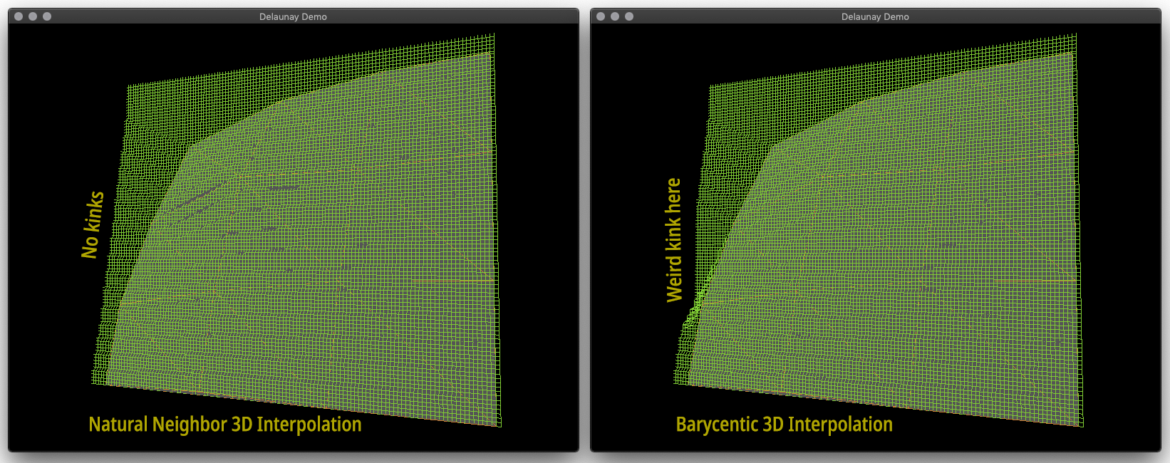
Natural Neighbor Interpolation (left) vs Barycentic Interpolation (right) in 3D perspective. Zoom in to see details. From https://github.com/lupyuen/interpolate-surface
Recall that we're using (X, Y) coordinates to interpolate a Z value. Which is shown above as the height of each point. (Like hilltops)
Barycentic Interpolation (right) has an unusual kink, so it doesn't look like a smooth interpolation.
Thus we picked Natural Neighbor Interpolation (left), which looks much smoother. This lets us verify visually that our pixels are indeed interpolated smoothly between the given points.
The smooth result of the 3D Interpolation is obvious... Straight lines are gently curved on the PineTime display. All this interpolated from only 16 points in the lower right quadrant!
Blinky distorted on a curved surface, interpolated from 16 points in the lower right quadrant
Now that we have precomputed the Lookup Tables PHYSICAL_TO_VIRTUAL_MAP and VIRTUAL_TO_PHYSICAL_MAP, let's embed them into PineTime's Flash ROM.
Here's how we embed PHYSICAL_TO_VIRTUAL_MAP, the array that maps every Physical Pixel to the corresponding Virtual Pixel...
/// For Physical (x,y) Coordinates, return the corresponding Virtual (x,y) Coordinates.
/// Used by the CHIP-8 Emulator to decide which Virtual Pixel to fetch the colour value when rendering a Physical Pixel.
/// (x,y) must belong to the X >= 0, Y >= 0 quadrant
fn map_physical_to_virtual_normalised(x: u8, y: u8) -> (u8, u8) {
    let x_index = x.min(PHYSICAL_TO_VIRTUAL_MAP_WIDTH as u8 - 1);
    let y_index = y.min(PHYSICAL_TO_VIRTUAL_MAP_HEIGHT as u8 - 1);
    let virtual_pixel = PHYSICAL_TO_VIRTUAL_MAP[y_index as usize][x_index as usize];  //  Returns (x,y)
    virtual_pixel
}

/// For each Physical (x,y) Coordinate, return the corresponding Virtual (x,y) Coordinates.
/// Used by the CHIP-8 Emulator to decide which Virtual Pixel to fetch the colour value when rendering a Physical Pixel.
/// Since X and Y are symmetric, this grid only covers one quadrant (X >= 0, Y >= 0)
static PHYSICAL_TO_VIRTUAL_MAP: &[[(u8,u8); PHYSICAL_TO_VIRTUAL_MAP_WIDTH]; PHYSICAL_TO_VIRTUAL_MAP_HEIGHT = &  //  Row=Y, Col=X
[               //  Copied from output of https://github.com/lupyuen/interpolate-surface
    [           //  Physical Row 0
        (0,0),  //  Physical Row 0, Col 0   => Virtual Col 0,  Row 0
        (0,0),  //  Physical Row 0, Col 1   => Virtual Col 0,  Row 0
        ...
        (32,0), //  Physical Row 0, Col 239 => Virtual Col 32, Row 0
    ],
    [           //  Physical Row 1
        (0,0),  //  Physical Row 1, Col 0   => Virtual Col 0,  Row 0
        (0,0),  //  Physical Row 1, Col 1   => Virtual Col 0,  Row 0
        ...
        (32,0), //  Physical Row 1, Col 239 => Virtual Col 32, Row 0
    ],
...
From https://github.com/lupyuen/pinetime-rust-mynewt/blob/master/rust/app/src/chip8.rs#L645-L673
PHYSICAL_TO_VIRTUAL_MAP is the Lookup Table precomputed by the generate_physical_to_virtual_map function that we have seen earlier. This is a 2D array with 100 rows and 120 columns, covering the Physical Pixels in the lower right quadrant of the PineTime display.
Each element of PHYSICAL_TO_VIRTUAL_MAP (indexed by Physical Row and Physical Column) is a tuple (Virtual X, Virtual Y), the coordinates of the mapped Virtual Pixel on CHIP-8.
map_physical_to_virtual_normalised is the function used to look up the PHYSICAL_TO_VIRTUAL_MAP table by Normalised Physical (X, Y) Coordinates.
/// For Physical (x,y) Coordinates, return the corresponding Virtual (x,y) Coordinates.
/// Used by the CHIP-8 Emulator to decide which Virtual Pixel to fetch the colour value when rendering a Physical Pixel.
fn map_physical_to_virtual(x: u8, y: u8) -> (u8, u8) {
    //  Check which quadrant (x,y) belongs to and flip accordingly
    let flip =  //  (flip for X, flip for Y)
        if x < PHYSICAL_WIDTH as u8 / 2 && y < PHYSICAL_HEIGHT as u8 / 2 {
            (true, true)  //  Top left quadrant: Flip horizontally and vertically
        } else if x >= PHYSICAL_WIDTH as u8 / 2 && y < PHYSICAL_HEIGHT as u8 / 2 {
            (false, true)   //  Top right quadrant: Flip vertically
        } else if x < PHYSICAL_WIDTH as u8 / 2 && y >= PHYSICAL_HEIGHT as u8 / 2 {
            (true, false)   //  Bottom left quadrant: Flip horizontally
        } else {
            (false, false)    //  Bottom right quadrant: Don't flip
        };
    let x_normalised =
        if flip.0 { PHYSICAL_WIDTH as u8 / 2 - x }
        else      { x - PHYSICAL_WIDTH as u8 / 2 };
    let y_normalised =
        if flip.1 { PHYSICAL_HEIGHT as u8 / 2 - y }
        else      { y - PHYSICAL_HEIGHT as u8 / 2 };
    let p = map_physical_to_virtual_normalised(x_normalised, y_normalised);  //  Returns (x,y)
    let p2 = (
        if flip.0 { SCREEN_WIDTH as u8 / 2 - p.0 }
        else      { p.0 + SCREEN_WIDTH as u8 / 2 }
        ,
        if flip.1 { SCREEN_HEIGHT as u8 / 2 - p.1 }
        else      { p.1 + SCREEN_HEIGHT as u8 / 2 }
    );
    //  Crop to screen size
    (
        p2.0.min(SCREEN_WIDTH as u8 - 1),
        p2.1.min(SCREEN_HEIGHT as u8 - 1),
    )
}
From https://github.com/lupyuen/pinetime-rust-mynewt/blob/master/rust/app/src/chip8.rs#L556-L590
map_physical_to_virtual is the function that maps the Actual (Unnormalised) Physical (X, Y) Coordinates to the Virtual (X, Y) Coordinates.
This function normalises the coordinates from the four quadrants of the screen into the lower right quadrant. Hence it flips and unflips the coordinates before and after calling map_physical_to_virtual_normalised. (Just like roti prata)
Here's how we embed VIRTUAL_TO_PHYSICAL_MAP, the array that maps every Virtual Pixel to the corresponding Physical Bounding Box... (The box that contains all Physical Pixels that map to the same Virtual Pixel)
/// For each Virtual (x,y) Coordinate, return the Bounding Box (left, top, right, bottom) that encloses the corresponding Physical (x,y) Coordinates.
/// Used by the CHIP-8 Emulator to decide which Physical Pixels to redraw when a Virtual Pixel is updated.
/// (x,y) must belong to the X >= 0, Y >= 0 quadrant
fn map_virtual_to_physical_normalised(x: u8, y: u8) -> (u8, u8, u8, u8) {
    let x_index = x.min(VIRTUAL_TO_PHYSICAL_MAP_WIDTH as u8 - 1);
    let y_index = y.min(VIRTUAL_TO_PHYSICAL_MAP_HEIGHT as u8 - 1);
    let physical_box = VIRTUAL_TO_PHYSICAL_MAP[y_index as usize][x_index as usize];  //  Returns (left,top,right,bottom)
    physical_box
}

/// For each Virtual (x,y) Coordinate, return the Bounding Box (left, top, right, bottom) that encloses the corresponding Physical (x,y) Coordinates.
/// Used by the CHIP-8 Emulator to decide which Physical Pixels to redraw when a Virtual Pixel is updated.
/// Since X and Y are symmetric, this grid only covers one quadrant (X >= 0, Y >= 0)
static VIRTUAL_TO_PHYSICAL_MAP: &[[(u8,u8,u8,u8); VIRTUAL_TO_PHYSICAL_MAP_WIDTH]; VIRTUAL_TO_PHYSICAL_MAP_HEIGHT] = &  //  Row=Y, Col=X
[                      //  Copied from output of https://github.com/lupyuen/interpolate-surface
    [                  //  Virtual Row 0
        (0,0,4,6),     //  Virtual Row 0, Col 0    => Physical Left Col 0,   Top Row 0, Right Col 4,  Bottom Row 6
        (5,0,8,6),     //  Virtual Row 0, Col 1    => Physical Left Col 5,   Top Row 0, Right Col 8,  Bottom Row 6
        ...
        (116,0,119,4), //  Virtual Row 0, Col 31   => Physical Left Col 116, Top Row 0, Right Col 119, Bottom Row 4
    ],
    [                  //  Virtual Row 1
        (0,7,4,12),    //  Virtual Row 1, Col 0    => Physical Left Col 0,   Top Row 7, Right Col 4,  Bottom Row 12
        (5,7,8,12),    //  Virtual Row 1, Col 1    => Physical Left Col 5,   Top Row 7, Right Col 8,  Bottom Row 12
        ...
        (116,5,119,9), //  Virtual Row 1, Col 31   => Physical Left Col 116, Top Row 5, Right Col 119, Bottom Row 9
    ],
...
From https://github.com/lupyuen/pinetime-rust-mynewt/blob/master/rust/app/src/chip8.rs#L654-L782
VIRTUAL_TO_PHYSICAL_MAP is the Lookup Table precomputed by the generate_virtual_to_physical_map function that we have seen earlier. This is a 2D array with 16 rows and 32 columns, covering the Virtual Pixels in the lower right quadrant of the CHIP-8 Emulator.
Each element of VIRTUAL_TO_PHYSICAL_MAP (indexed by Virtual Row and Virtual Column) is a tuple (Physical Left, Physical Top, Physical Right, Physical Bottom), the coordinates of the mapped Physical Bounding Box on the PineTime display.
map_virtual_to_physical_normalised is the function used to look up the VIRTUAL_TO_PHYSICAL_MAP table by Normalised Virtual (X, Y) Coordinates.
/// For each Virtual (x,y) Coordinate, return the Bounding Box (left, top, right, bottom) that encloses the corresponding Physical (x,y) Coordinates.
/// Used by the CHIP-8 Emulator to decide which Physical Pixels to redraw when a Virtual Pixel is updated.
#[cfg(feature = "chip8_curve")]  //  If we are rendering CHIP8 Emulator as curved surface...
fn map_virtual_to_physical(x: u8, y: u8) -> (u8, u8, u8, u8) {
    //  Check which quadrant (x,y) belongs to and flip accordingly
    let flip =  //  (flip for X, flip for Y)
        if x < SCREEN_WIDTH as u8 / 2 && y < SCREEN_HEIGHT as u8 / 2 {
            (true, true)  //  Top left quadrant: Flip horizontally and vertically
        } else if x >= SCREEN_WIDTH as u8 / 2 && y < SCREEN_HEIGHT as u8 / 2 {
            (false, true)   //  Top right quadrant: Flip vertically
        } else if x < SCREEN_WIDTH as u8 / 2 && y >= SCREEN_HEIGHT as u8 / 2 {
            (true, false)   //  Bottom left quadrant: Flip horizontally
        } else {
            (false, false)    //  Bottom right quadrant: Don't flip
        };
    let x_normalised =
        if flip.0 { SCREEN_WIDTH as u8 / 2 - x }
        else      { x - SCREEN_WIDTH as u8 / 2 };
    let y_normalised =
        if flip.1 { SCREEN_HEIGHT as u8 / 2 - y }
        else      { y - SCREEN_HEIGHT as u8 / 2 };
    let b = map_virtual_to_physical_normalised(x_normalised, y_normalised);  //  Returns (left,top,right,bottom)
    let b2 = (
        if flip.0 { PHYSICAL_WIDTH as u8 / 2 - b.0 }
        else      { b.0 + PHYSICAL_WIDTH as u8 / 2 }
        ,
        if flip.1 { PHYSICAL_HEIGHT as u8 / 2 - b.1 }
        else      { b.1 + PHYSICAL_HEIGHT as u8 / 2 }
        ,
        if flip.0 { PHYSICAL_WIDTH as u8 / 2 - b.2 }
        else      { b.2 + PHYSICAL_WIDTH as u8 / 2 }
        ,
        if flip.1 { PHYSICAL_HEIGHT as u8 / 2 - b.3 }
        else      { b.3 + PHYSICAL_HEIGHT as u8 / 2 }
    );
    //  Crop to screen size
    let crop = (
        b2.0.min(PHYSICAL_WIDTH as u8 - 1),   //  Left
        b2.1.min(PHYSICAL_HEIGHT as u8 - 1),  //  Top
        b2.2.min(PHYSICAL_WIDTH as u8 - 1),   //  Right
        b2.3.min(PHYSICAL_HEIGHT as u8 - 1),  //  Bottom
    );
    //  Flip left and right, top and bottom if necessary
    let result = (
        crop.0.min(crop.2),  //  Left
        crop.1.min(crop.3),  //  Top
        crop.0.max(crop.2),  //  Right
        crop.1.max(crop.3),  //  Bottom
    );
    assert!(result.0 <= result.2 && result.1 <= result.3, "flip error");  //  Left <= Right and Top <= Bottom
    result
}
From https://github.com/lupyuen/pinetime-rust-mynewt/blob/master/rust/app/src/chip8.rs#L592-L643
map_virtual_to_physical is the function that maps the Actual (Unnormalised) Virtual (X, Y) Coordinates to the Physical (Left, Top, Right, Bottom) Bounding Box.
This function normalises the coordinates from the four quadrants of the screen into the lower right quadrant. Hence it flips and unflips the coordinates before and after calling map_virtual_to_physical_normalised. (Just like pizza)
How shall we use the two Lookup Tables and their access functions map_physical_to_virtual, map_virtual_to_physical?
Remember PixelIterator, our Rust Iterator that returns a sequence of Physical Pixel Colours (16-bit) that will be rendered for a Physical Block of PineTime pixels?
Here's the updated PixelIterator for rendering pixels on a curved surface...
/// Implement the Iterator for Virtual Pixels in a Virtual Block
impl Iterator for PixelIterator {
    /// This Iterator returns Physical Pixel colour words (16-bit)
    type Item = u16;
    ...
    /// Return the next Physical Pixel colour
    #[cfg(feature = "chip8_curve")]  //  If we are rendering CHIP8 Emulator as curved surface...
    fn next(&mut self) -> Option<Self::Item> {
        if self.y_physical > self.physical_bottom { return None; }  //  No more Physical Pixels
        assert!(self.x_physical < PHYSICAL_WIDTH as u8, "x overflow");
        assert!(self.y_physical < PHYSICAL_HEIGHT as u8, "y overflow");

        //  Map the Physical Pixel to the Virtual Pixel
        let virtual_pixel = map_physical_to_virtual(self.x_physical, self.y_physical);

        if self.x == virtual_pixel.0 && self.y == virtual_pixel.1 {
            //  If rendering the same Virtual Pixel, increment the offset
            self.x_offset += 1;
        } else {
            //  If rendering a different Virtual Pixel, reset the offset
            self.x = virtual_pixel.0;
            self.y = virtual_pixel.1;
            self.x_offset = 0;
            self.y_offset = 0;
        }

        //  Get the colour from the Virtual Screen Buffer
        let color = self.get_color();

        //  Loop over x_physical from physical_left to physical_right
        self.x_physical += 1;
        if self.x_physical > self.physical_right {
            self.x_physical = self.physical_left;
            //  Loop over y_physical from physical_top to physical_bottom
            self.y_physical += 1;
        }

        //  Return the Physical Pixel color
        return Some(color);
    }
From https://github.com/lupyuen/pinetime-rust-mynewt/blob/master/rust/app/src/chip8.rs#L457-L491
The new PixelIterator steps through each Physical PineTime Pixel in a block and calls map_physical_to_virtual to find the corresponding Virtual CHIP-8 Pixel and its colour.
With curved distortion, a Virtual CHIP-8 Pixel no longer maps to a rectangular block of Physical PineTime Pixels... It actually maps to a curved block of Physical Pixels.
To simplify the rendering, we'll just consider the Bounding Box of the Physical Pixels. Which may overlap partially with other Virtual Pixels... But the extra rendering should be fine.
Here's how we get the Bounding Box of Physical Pixels for a Virtual Pixel...
/// Return Bounding Box of Physical Pixels (left, top, right, bottom) that correspond to the Virtual Pixels
#[cfg(feature = "chip8_curve")]  //  If we are rendering CHIP8 Emulator as curved surface...
fn get_bounding_box(virtual_left: u8, virtual_top: u8, virtual_right: u8, virtual_bottom: u8) -> (u8, u8, u8, u8) {
    //  One Virtual Pixel may map to multiple Physical Pixels, so we lookup the Physical Bounding Box.
    //  TODO: Handle wide and tall Bounding Boxes
    let physical_left_top = map_virtual_to_physical(virtual_left, virtual_top);  //  Returns (left,top,right,bottom)
    let physical_right_bottom = map_virtual_to_physical(virtual_right, virtual_bottom);

    let left: u8 = physical_left_top.0;
    let top: u8 = physical_left_top.1;
    let right: u8 = physical_right_bottom.2.min(PHYSICAL_WIDTH as u8 - 1);
    let bottom: u8 = physical_right_bottom.3.min(PHYSICAL_HEIGHT as u8 - 1);
    assert!(left < PHYSICAL_WIDTH as u8 && top < PHYSICAL_HEIGHT as u8 && right < PHYSICAL_WIDTH as u8 && bottom < PHYSICAL_HEIGHT as u8, "overflow");
    ( left, top, right, bottom )  //  Return the Physical Bounding Box
}
From https://github.com/lupyuen/pinetime-rust-mynewt/blob/master/rust/app/src/chip8.rs#L523-L538
The above curved version of get_bounding_box is called by render_region to determine which Physical Pixels need to be redrawn whenever the CHIP-8 screen is updated.
Will this curved distortion for CHIP-8 bloat the PineTime firmware size? Will the Lookup Tables for the curved mapping fit comfortably into PineTime's Flash ROM (512 KB)?
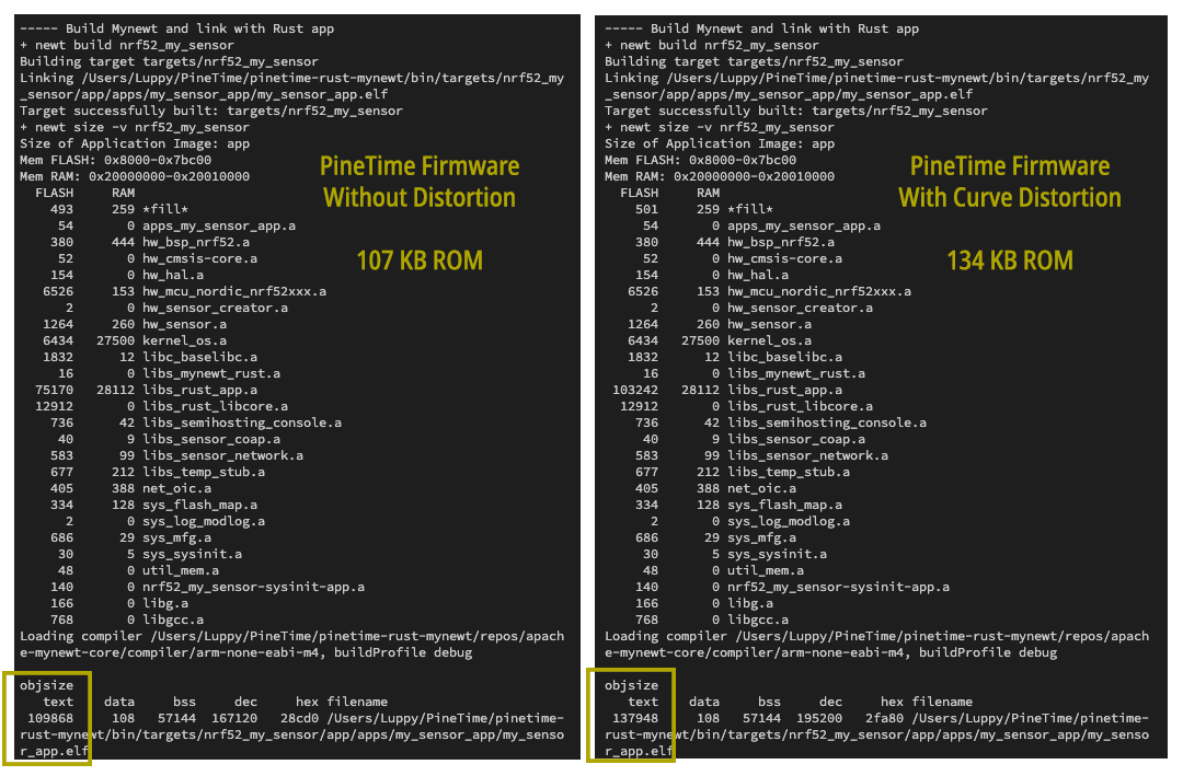
PineTime Firmware Size without distortion (left) and with curved distortion (right)
Amazingly... NO not much bloat, and YES the tables fit into ROM! Only 27 KB of Flash ROM was needed to store the Lookup Tables! (No extra RAM needed)
Take a look at the demo video... Rendering CHIP-8 on a curved surface doesn't seem to affect the game performance. Lookup Tables in ROM work really well for curved rendering!
▶️ 抖音视频