📝 22 May 2022
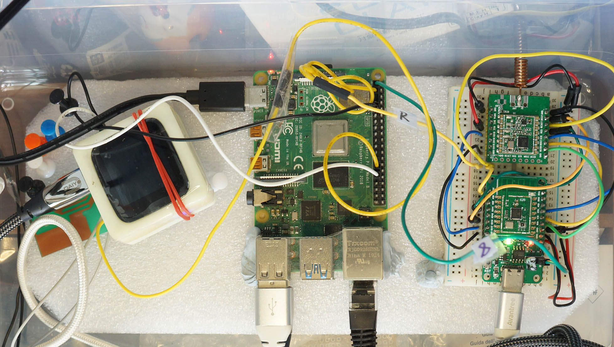
PineDio Stack BL604 (left, with unglam rubber band) and PineCone BL602 (right) connected to Single-Board Computer for Automated Testing
Pine64 is about to launch their most exciting RISC-V IoT gadget: PineDio Stack BL604 RISC-V Board with Touch Screen, LoRa and many other features.
This is a cautionary tale concerning Alice, Bob and Chow, the (Hypothetical) Embedded Devs collaborating remotely on the newly-released PineDio Stack…
Alice: Hi All! I’m building an I2C Driver for PineDio Stack’s Accelerometer. Where can I get the latest build of Apache NuttX RTOS for PineDio Stack?
Bob: You’ll have to compile it yourself from the source code here. But beware… Some folks reported (unconfirmed) that it might run differently depending on the RISC-V Compiler Toolchain.
Chow: OH CR*P! PineDio Stack’s I2C Touch Panel is no longer responding to touch! What changed?!
Alice: Is it because of the I2C Accelerometer Driver that I just committed to the repo?
Bob: Uhhh I think it might be the BL602 Updates from NuttX Mainline that I merged last night. I forgot to test the changes. I think SPI and LoRaWAN are broken too. Sorry!
Sounds like a nightmare, but this story could be real. Robert Lipe and I are already facing similar challenges today.
Let’s intervene and rewrite the narrative…
Alice: Hi All! I’m building an I2C Driver for PineDio Stack’s Accelerometer. Where can I get the latest build of Apache NuttX RTOS for PineDio Stack?
Bob: Just download the Compiled Firmware from the GitHub Releases here. It was built automatically by GitHub Actions with the same RISC-V Compiler Toolchain that we’re all using.
Chow: Hmmm PineDio Stack’s I2C Touch Panel works a little wonky today. What changed?
Alice: It can’t be caused by my new I2C Accelerometer Driver. My changes to the repo are still awaiting Automated Testing.
Bob: I merged the BL602 Updates from NuttX Mainline last night. The I2C Touch Panel worked perfectly OK during Automated Testing, here’s the evidence: Automated Testing Log. Maybe we do some static discharge? Switch off the AC, open the windows, remove all metal objects, …
Automated Testing Log for PineDio Stack
This article explains how we accomplished all that with PineDio Stack…
Fully Automated Testing of all NuttX Releases for PineDio Stack: GPIO, SPI, Timers, Multithreading, LoRaWAN
Includes Automated Testing of NuttX Mainline Updates
Mostly Automated Testing of I2C Touch Panel
(Needs one Human Touch, in lieu of a Robot Finger)
Firmware Builds are auto-downloaded from GitHub Releases for testing
(Auto-published by GitHub Actions)
Testing Logs are auto-uploaded to GitHub Releases as Release Notes
Let’s dive into the Auto Flash and Test Script for PineDio Stack…
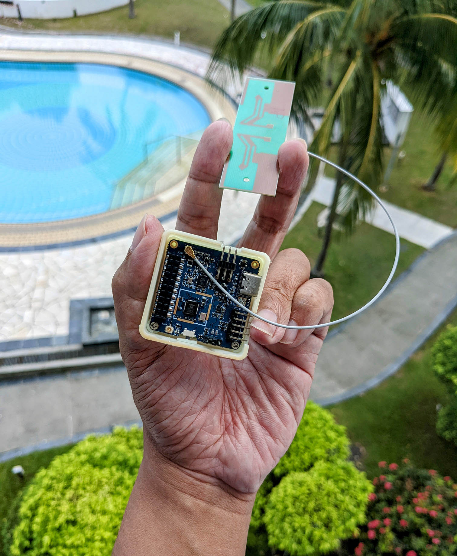
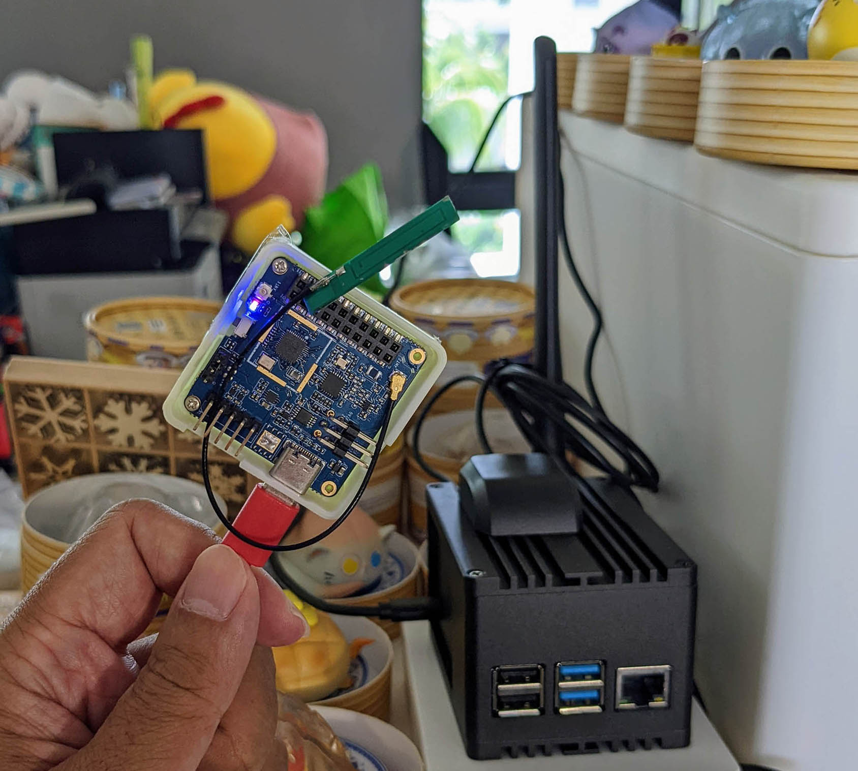
PineDio Stack BL604 connected to LoRa Antenna (swiped from the IoT Course I used to teach)
Before we study the script, let’s break down the Automated Testing into a series of Testing Checkpoints.
These are our success criteria for NuttX on PineDio Stack…
NuttX must boot on PineDio Stack, with NuttX Drivers loaded (Checkpoint Alpha)
NuttX must not crash on PineDio Stack (Checkpoint Bravo)
(If NuttX crashes, our script runs a Crash Analysis)
SPI Transmit and Receive must work (Checkpoint Charlie)
GPIO Input, Output and Interrupt must work (Checkpoint Delta)
(Also Timers and Multithreading with SX1262 LoRa Transceiver)
I2C Transmit and Receive must work (Checkpoint Echo)
(With CST816S Touch Panel)
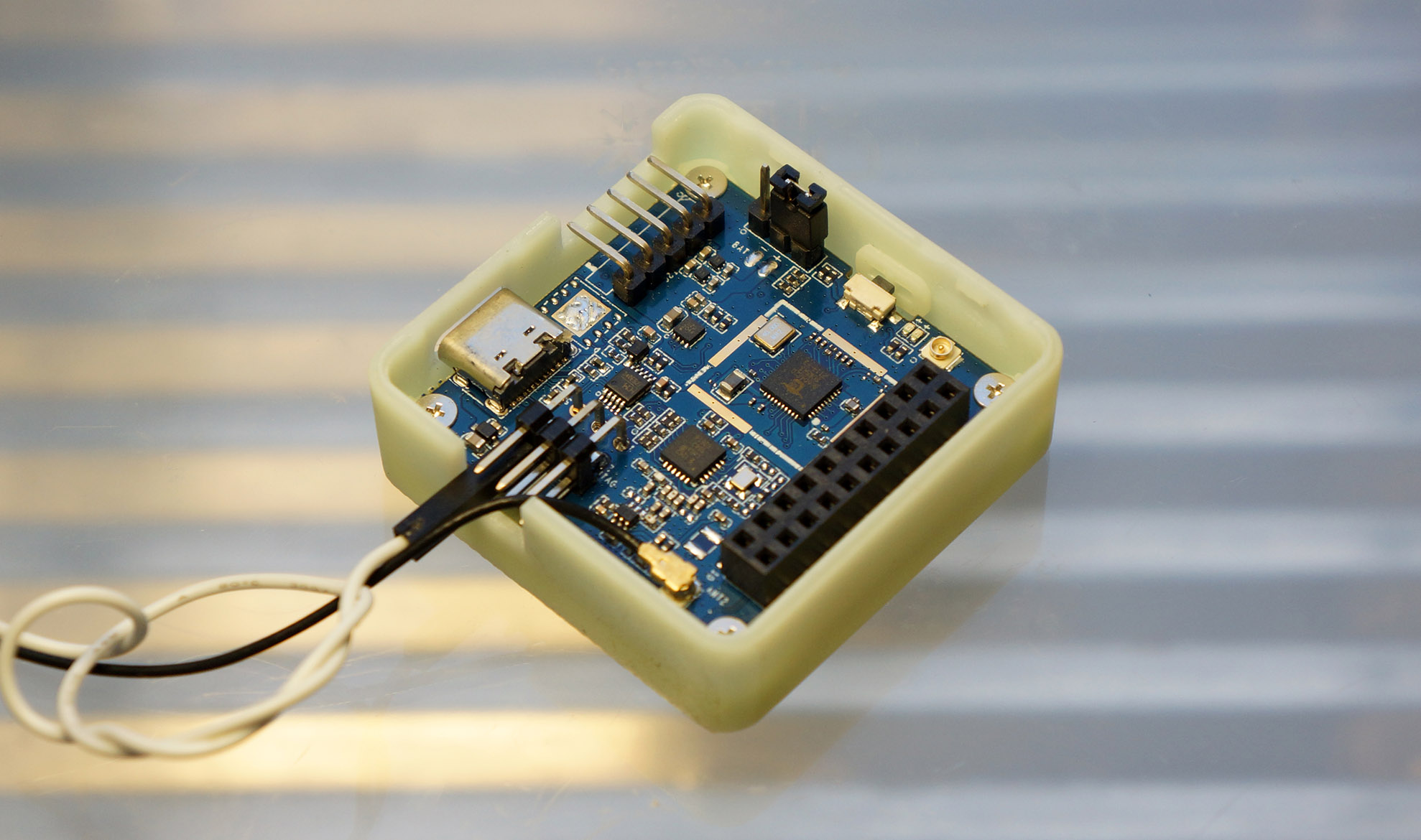
To run the above tests automatically, let’s connect PineDio Stack to a Single-Board Computer.
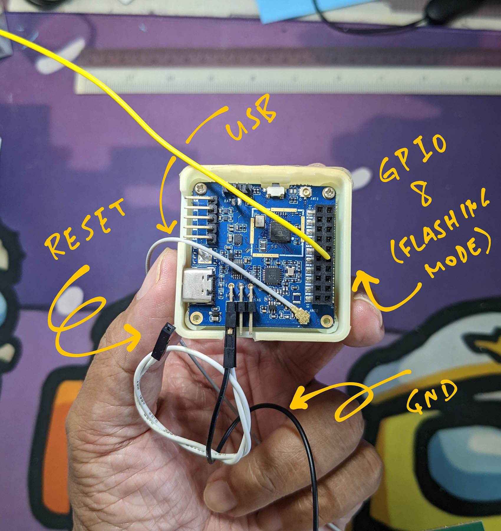
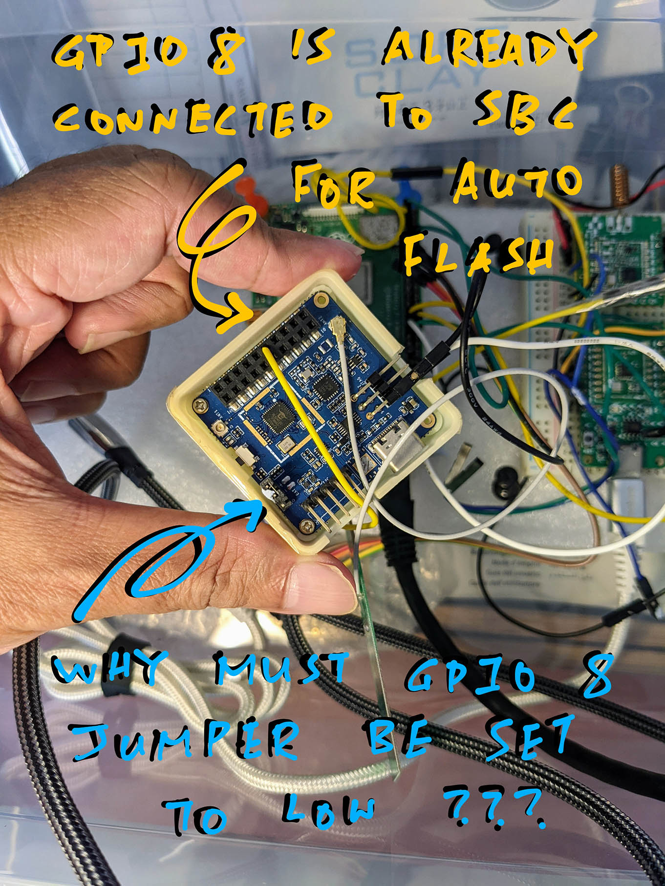
GPIO 8, Reset and Ground on PineDio Stack BL604
Our Automated Testing Script runs on a Single-Board Computer (SBC) to…
Control the Flashing and Testing of PineDio Stack
(Via USB, GPIO 8 and Reset)
Capture the Test Log and upload to the GitHub Release
(Over USB)
We connect PineDio Stack to our SBC like so…
| SBC | BL604 | Function |
|---|---|---|
| GPIO 5 | GPIO 8 (GPIO Port) | Flashing Mode |
| GPIO 6 | RST (JTAG Port) | Reset |
| GND | GND (JTAG Port) | Ground |
| USB | USB Port | USB UART |
GPIO 8 is exposed on the GPIO Port (inside PineDio Stack). Reset and Ground are exposed on the JTAG Port (outside PineDio Stack).
(See the pic above)
The GPIO 8 Jumper must be set to Low (Non-Flashing Mode)…
(Or the LoRaWAN Test will fail because the timers get triggered too quickly, not sure why)
Remember to connect a LoRa Antenna! (See this)
Close the Back Cover of PineDio Stack, without the GPS Base Board.
We’ll see something similar to the pic below. We’re ready to run our Automated Testing Script!
So PineDio Stack will be permanently connected to our SBC?
Yep I have a Spare PineDio Stack permanently connected to my SBC.
This PineDio Stack has a faulty ST7789 Display (hence it’s a spare), so we can’t auto-test the ST7789 Display.
(But since ST7789 Display and SX1262 LoRa Transceiver are connected to the same SPI Bus, it should be OK to test only the SX1262 Transceiver)
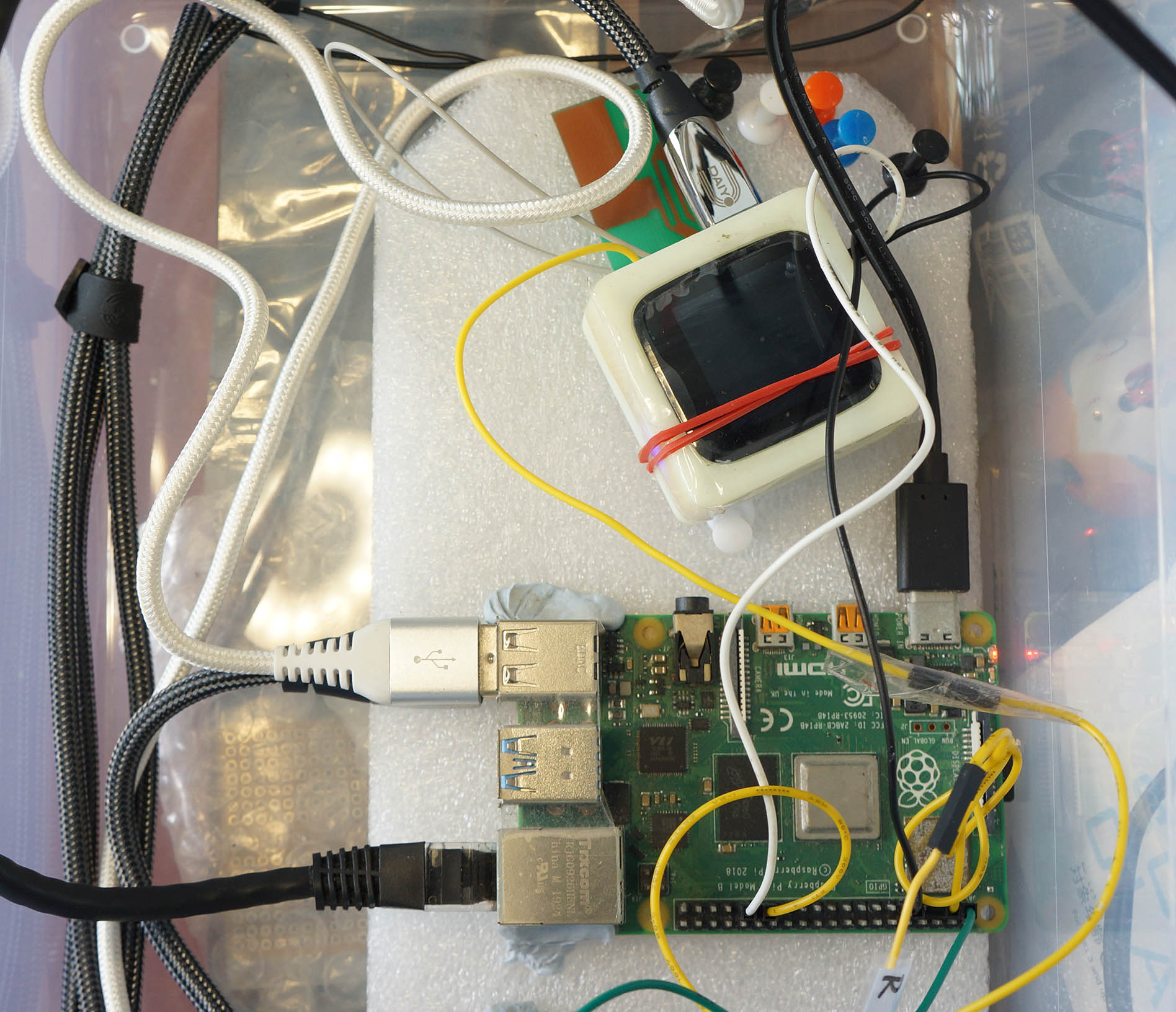
PineDio Stack BL604 connected to SBC
To run the Automated Testing Script on our Single-Board Computer…
##  Allow the user to access the GPIO and UART ports
sudo usermod -a -G gpio    $USER
sudo usermod -a -G dialout $USER

##  Logout and login to refresh the permissions
logout

##  TODO: Install rustup, select default option.
##  See https://rustup.rs

##  Install blflash for flashing PineDio Stack
##  https://github.com/spacemeowx2/blflash
cargo install blflash

##  Download the flash and test script
git clone --recursive https://github.com/lupyuen/remote-bl602/

##  Always sync the clock before running the script
sudo apt install ntpdate
sudo ntpdate -u time.nist.gov
date

##  Run the script for Auto Flash and Test for PineDio Stack BL604.
##  Capture the Test Log in /tmp/release.log
script -c remote-bl602/scripts/pinedio.sh /tmp/release.log

##  TODO: Install the GitHub CLI for uploading Release Notes: https://cli.github.com
##  Log in a GitHub Token that has "repo" and "read:org" permissions

##  Optional: Upload the Test Log to the GitHub Release Notes
remote-bl602/scripts/upload.sh
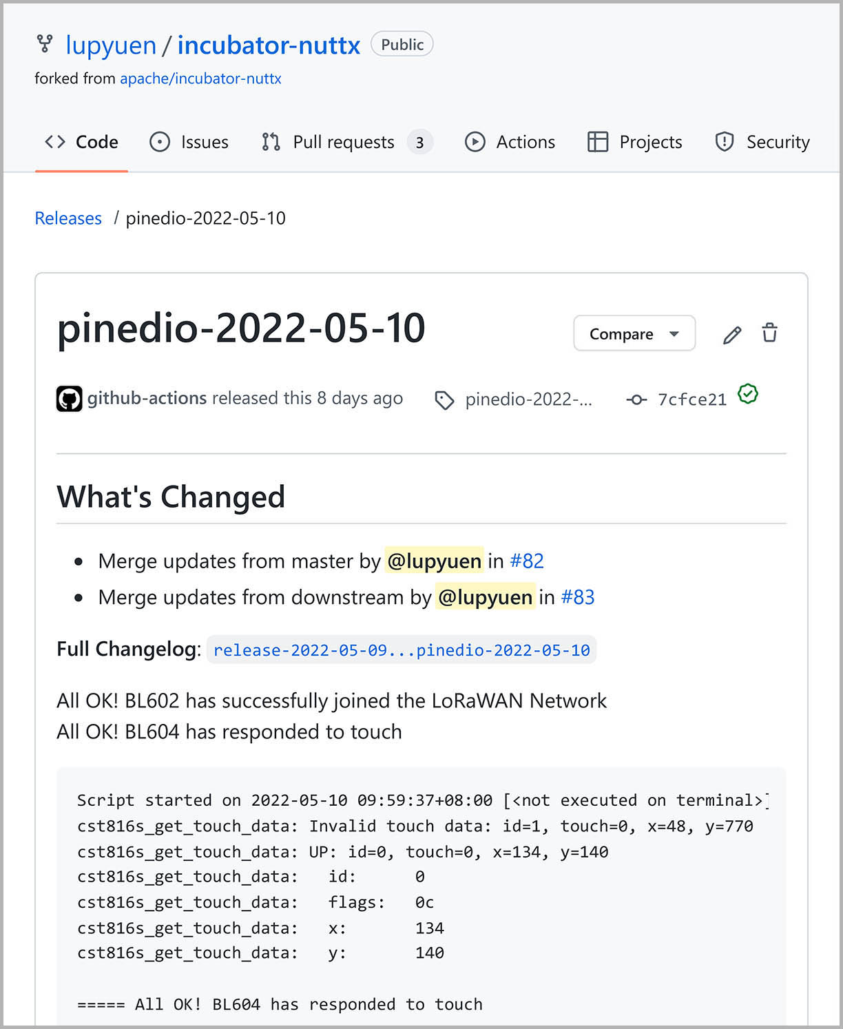
This will download and test Today’s Build of NuttX for PineDio Stack (published on GitHub Releases).
(Here’s the build for 2022-05-10)
If the Automated Test succeeds, we’ll see…
Download the latest pinedio NuttX build for 2022-05-10
Flash BL602 over USB UART with blflash
...
All OK! BL602 has successfully joined the LoRaWAN Network
All OK! BL604 has responded to touch
Beware: The script fails silently if there’s no NuttX Build for today. (Sorry!)
Can we pick a different NuttX Build?
We pick a NuttX Build from this list…
Then we set BUILD_DATE like so…
##  Tell the script to download the build for 2022-05-10
export BUILD_DATE=2022-05-10

##  Run the script for Auto Flash and Test for PineDio Stack BL604.
##  Capture the Test Log in /tmp/release.log
script -c remote-bl602/scripts/pinedio.sh /tmp/release.log
Will this work over SSH?
Yep we may run the Automated Test remotely over SSH…
ssh my-sbc remote-bl602/scripts/pinedio.sh
How is NuttX for PineDio Stack built and published to GitHub Releases?
Whenever we commit changes to the NuttX Repo for PineDio Stack, GitHub Actions will trigger a new NuttX Build and publish the built firmware to GitHub Releases…
Our script downloads the NuttX Firmware from GitHub Releases for Automated Testing: pinedio.sh
##  BUILD_PREFIX is "pinedio"
##  BUILD_DATE defaults to today's date, like "2022-05-10"

##  Download the NuttX Firmware from GitHub Releases
wget -q https://github.com/lupyuen/nuttx/releases/download/$BUILD_PREFIX-$BUILD_DATE/nuttx.zip -O /tmp/nuttx.zip
pushd /tmp
unzip -o nuttx.zip
popd

##  Write the Release Tag for uploading the Test Log later:
##  "pinedio-2022-05-10"
echo "$BUILD_PREFIX-$BUILD_DATE" >/tmp/release.tag
We’ll see release.tag later when we upload the Test Log to the GitHub Release.
Let’s walk through the Automated Testing Script and find out how it implements each Testing Checkpoint.
NuttX booting on PineDio Stack
(Checkpoint Alpha)
Earlier we saw our Automated Testing Script downloading the NuttX Firmware from GitHub Releases.
At the first checkpoint, our script flashes the NuttX Firmware to PineDio Stack…
Set GPIO 5 to High (BL602 Flashing Mode)
Toggle GPIO 6 High-Low-High (Reset BL602)
BL602 is now in Flashing Mode
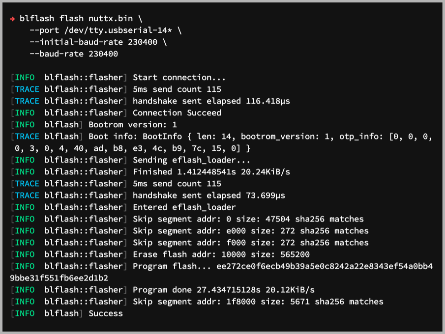
Flash BL602 over USB UART with blflash
+ blflash flash /tmp/nuttx.bin --port /dev/ttyUSB0
Sending eflash_loader...
Program flash...
Success
Our script restarts PineDio Stack in Flashing Mode and calls blflash to flash the NuttX Firmware.
Next our script restarts PineDio Stack in Normal Mode to start the NuttX Firmware…
Set GPIO 5 to Low (BL602 Normal Mode)
Toggle GPIO 6 High-Low-High (Reset BL602)
BL602 is now in Normal Mode

NuttShell (NSH) NuttX-10.3.0-RC0
nsh>
The NuttX Shell appears. Our script sends this command to reveal the NuttX Commit ID and Build Timestamp…
nsh> uname -a
NuttX 10.3.0-RC0 3e60d2211d May 10 2022 01:55:54 risc-v bl602evb
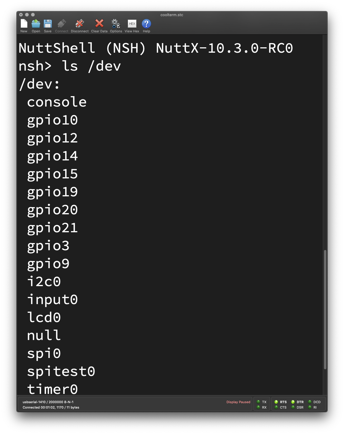
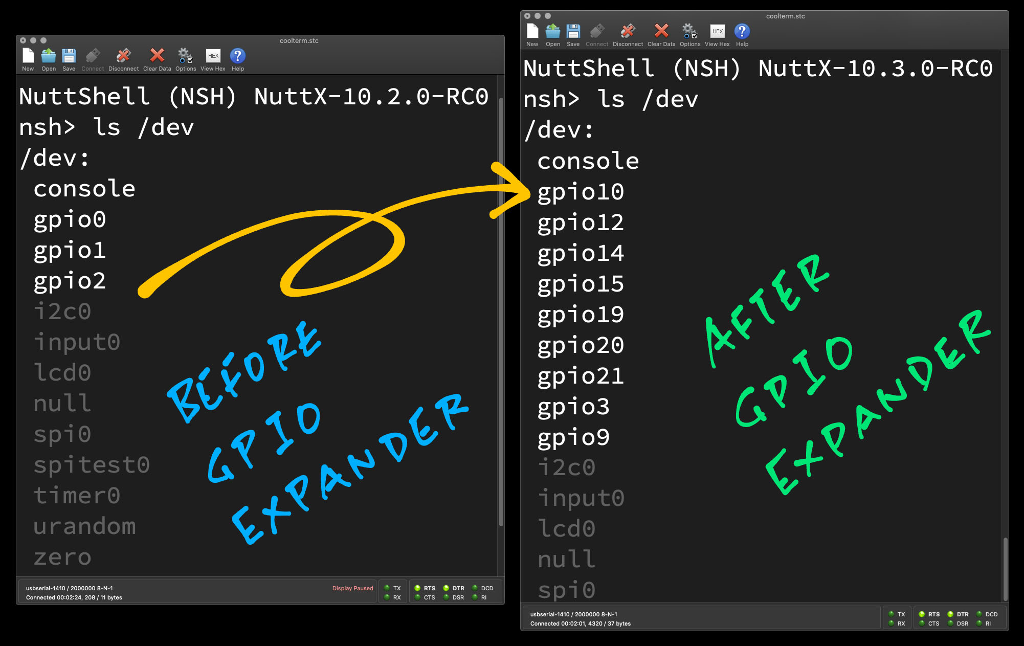
Then it lists the Device Drivers loaded on NuttX…
nsh> ls /dev
/dev:
 console  i2c0
 gpio10   input0
 gpio12   lcd0
 gpio14   null
 gpio15   spi0
 gpio19   spitest0
 gpio20   timer0
 gpio21   urandom
 gpio3    zero
 gpio9
Shown above are these NuttX Device Drivers: GPIO Expander, I2C, Touch Input, LCD Display, SPI Test, Timer and Random Number Generator.
Yep NuttX has successfully booted on PineDio Stack! Let’s dive into our Automated Testing Script and see the implementation of the operations above.
Flashing NuttX to PineDio Stack
Our script controls PineDio Stack through GPIO 5 and 6 on our SBC…
SBC GPIO 5: Selects Flashing Mode or Normal Mode on PineDio Stack
(Connected to PineDio Stack GPIO 8)
SBC GPIO 6: Restarts PineDio Stack
(Connected to PineDio Stack Reset Pin)
This is how our script configures GPIO 5 and 6 on our SBC: pinedio.sh
##  Enable GPIO 5 and 6
if [ ! -d /sys/class/gpio/gpio5 ]; then
  echo 5 >/sys/class/gpio/export ; sleep 1  ##  Must sleep or next GPIO command will fail with "Permission Denied"
fi
if [ ! -d /sys/class/gpio/gpio6 ]; then
  echo 6 >/sys/class/gpio/export ; sleep 1  ##  Must sleep or next GPIO command will fail with "Permission Denied"
fi

##  Set GPIO 5 and 6 as output
echo out >/sys/class/gpio/gpio5/direction
echo out >/sys/class/gpio/gpio6/direction
To switch PineDio Stack to Flashing Mode, we set GPIO 5 to High and restart PineDio Stack…
##  Set GPIO 5 to High (BL602 Flashing Mode)
echo 1 >/sys/class/gpio/gpio5/value ; sleep 1

##  Toggle GPIO 6 High-Low-High (Reset BL602)
echo 1 >/sys/class/gpio/gpio6/value ; sleep 1
echo 0 >/sys/class/gpio/gpio6/value ; sleep 1
echo 1 >/sys/class/gpio/gpio6/value ; sleep 1
We run the blflash command to flash the NuttX Firmware…
##  BL602 is now in Flashing Mode
##  Flash BL602 over USB UART with blflash
set -x  ##  Enable echo
blflash flash /tmp/nuttx.bin --port /dev/ttyUSB0
set +x  ##  Disable echo
sleep 1
After flashing NuttX, we switch PineDio Stack back to Normal Mode…
##  Set GPIO 5 to Low (BL602 Normal Mode)
echo 0 >/sys/class/gpio/gpio5/value ; sleep 1

##  Toggle GPIO 6 High-Low-High (Reset BL602)
echo 1 >/sys/class/gpio/gpio6/value ; sleep 1
echo 0 >/sys/class/gpio/gpio6/value ; sleep 1
echo 1 >/sys/class/gpio/gpio6/value ; sleep 1
We configure the USB Port for 2 Mbps and capture the Console Output from PineDio Stack…
##  Set USB UART to 2 Mbps
stty -F /dev/ttyUSB0 raw 2000000

##  Show the BL602 output and capture to /tmp/test.log.
##  Run this in the background so we can kill it later.
cat /dev/ttyUSB0 | tee /tmp/test.log &
Finally we send the uname and ls commands, to show the NuttX Build Details and the loaded Device Drivers…
##  If BL602 has not crashed, send the test command to BL602
echo "uname -a" >/dev/ttyUSB0 ; sleep 1
echo "ls /dev"  >/dev/ttyUSB0 ; sleep 1
Let’s move on to the second checkpoint.
(Checkpoint Bravo)
What happens when NuttX crashes during testing?
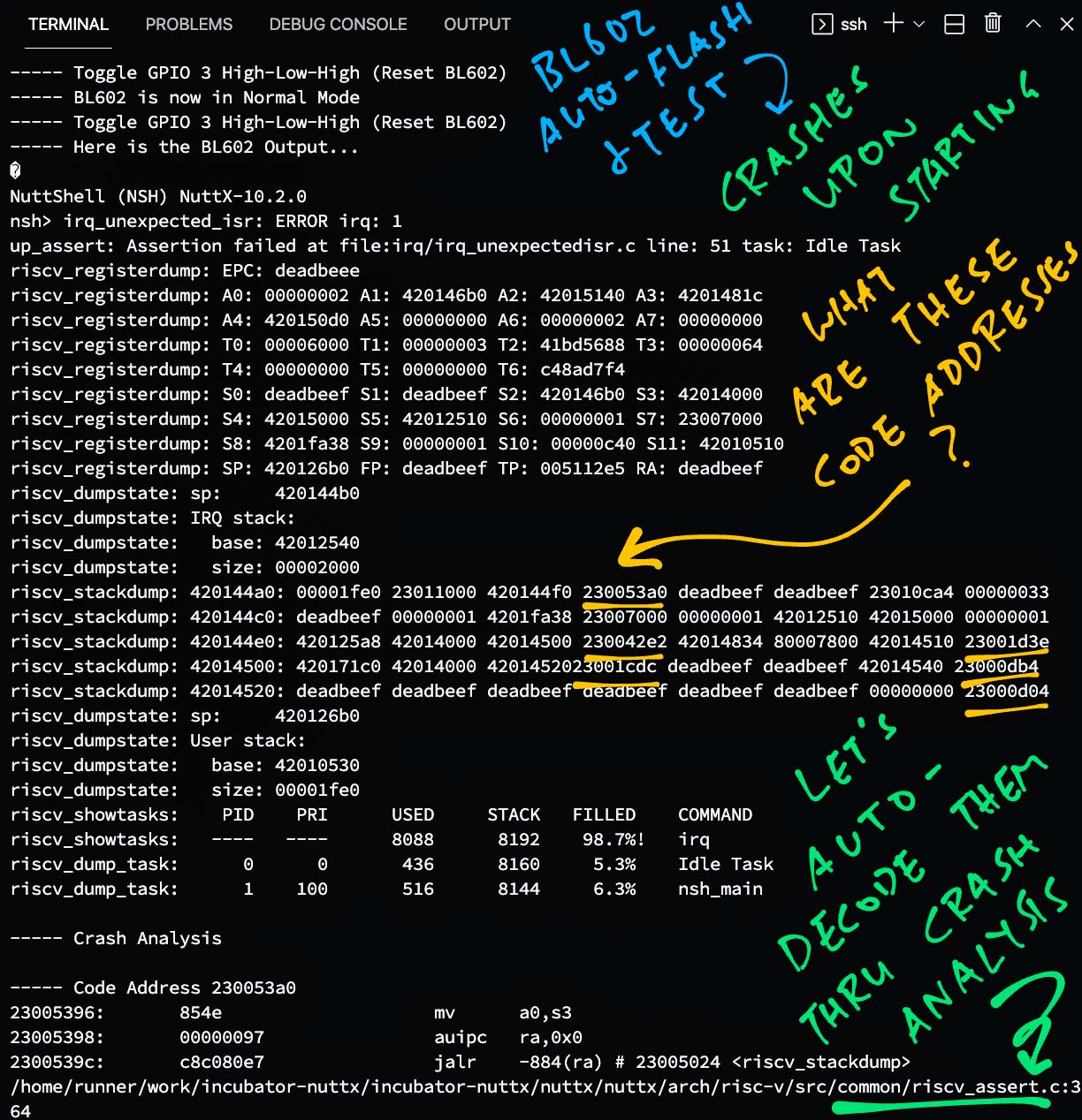
NuttX shows a Register and Stack Dump, like the pic above…
irq_unexpected_isr: ERROR irq: 1
up_assert: Assertion failed at file:irq/irq_unexpectedisr.c line: 51 task: Idle Task
riscv_registerdump: EPC: deadbeee
riscv_registerdump: A0: 00000002 A1: 420146b0 A2: 42015140 A3: 420141c
...
riscv_stackdump: 420144a0: 00001fe0 23011000 420144f0 230053a0 deadbeef deadbeef 23010ca4 00000033
riscv_stackdump: 420144c0: deadbeef 00000001 4201fa38 23007000 00000001 42012510 42015000 00000001
Our script can’t proceed with the Automated Testing, but it can help us make sense of these numbers to understand why NuttX crashed.
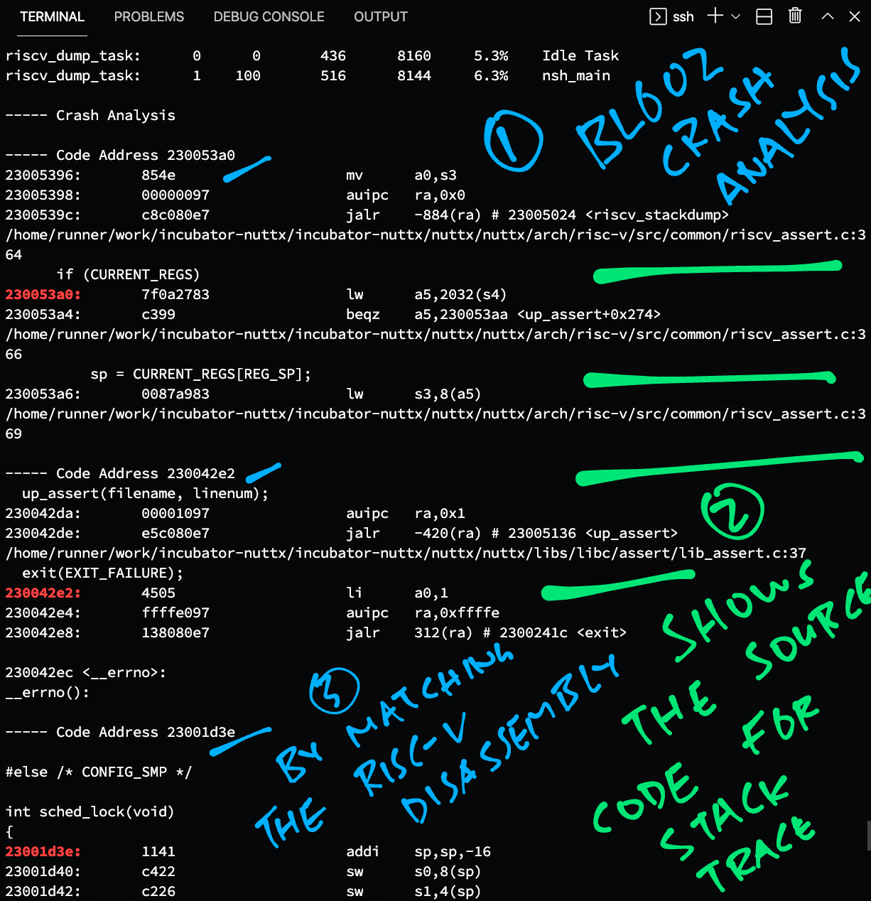
Our script detects the crash and does a Crash Analysis (pic below)…
----- Crash Analysis
Code Address 230053a0:
arch/risc-v/src/common/riscv_assert.c:364
  if (CURRENT_REGS)
    sp = CURRENT_REGS[REG_SP];

Code Address 230042e2:
libs/libc/assert/lib_assert.c:37
  exit(EXIT_FAILURE);
Through this Crash Analysis, we get some idea which lines of code caused the crash.
And hopefully we can heal NuttX on PineDio Stack!
Over to the implementation. Our script detects that NuttX has crashed when it sees the registerdump keyword: pinedio.sh
##  Check whether BL602 has crashed
set +e  ##  Don't exit when any command fails
match=$(grep "registerdump" /tmp/test.log)
set -e  ##  Exit when any command fails

##  If NuttX has booted properly, run the LoRaWAN Test
if [ "$match" != "" ]; then
  ...
else
  ##  If NuttX has crashed, do the Crash Analysis
  ...
Then it proceeds to decode the Stack Dump by matching the addresses with the RISC-V Disassembly: pinedio.sh
##  If NuttX has crashed, do the Crash Analysis.
##  Find all code addresses 23?????? in the Output Log, remove duplicates, skip 23007000.
##  Returns a newline-delimited list of addresses: "23011000\n230053a0\n..."
grep --extended-regexp \
  --only-matching \
  "23[0-9a-f]{6}" \
  /tmp/test.log \
  | grep -v "23007000" \
  | uniq \
  >/tmp/test.addr

##  For every address, show the corresponding line in the disassembly
for addr in $(cat /tmp/test.addr); do
  ##  Skip addresses that don't match
  match=$(grep "$addr:" /tmp/nuttx.S)
  if [ "$match" != "" ]; then
    echo "----- Code Address $addr"
    grep \
      --context=5 \
      --color=auto \
      "$addr:" \
      /tmp/nuttx.S
    echo
  fi
done
The Crash Analysis is explained here…
There’s a Design Flaw in our script that needs fixing… It doesn’t detect crashes while running the SPI, LoRaWAN and Touch Panel Tests. (See this)
(We should probably use a State Machine instead of a long chain of hacky “if-else” statements)
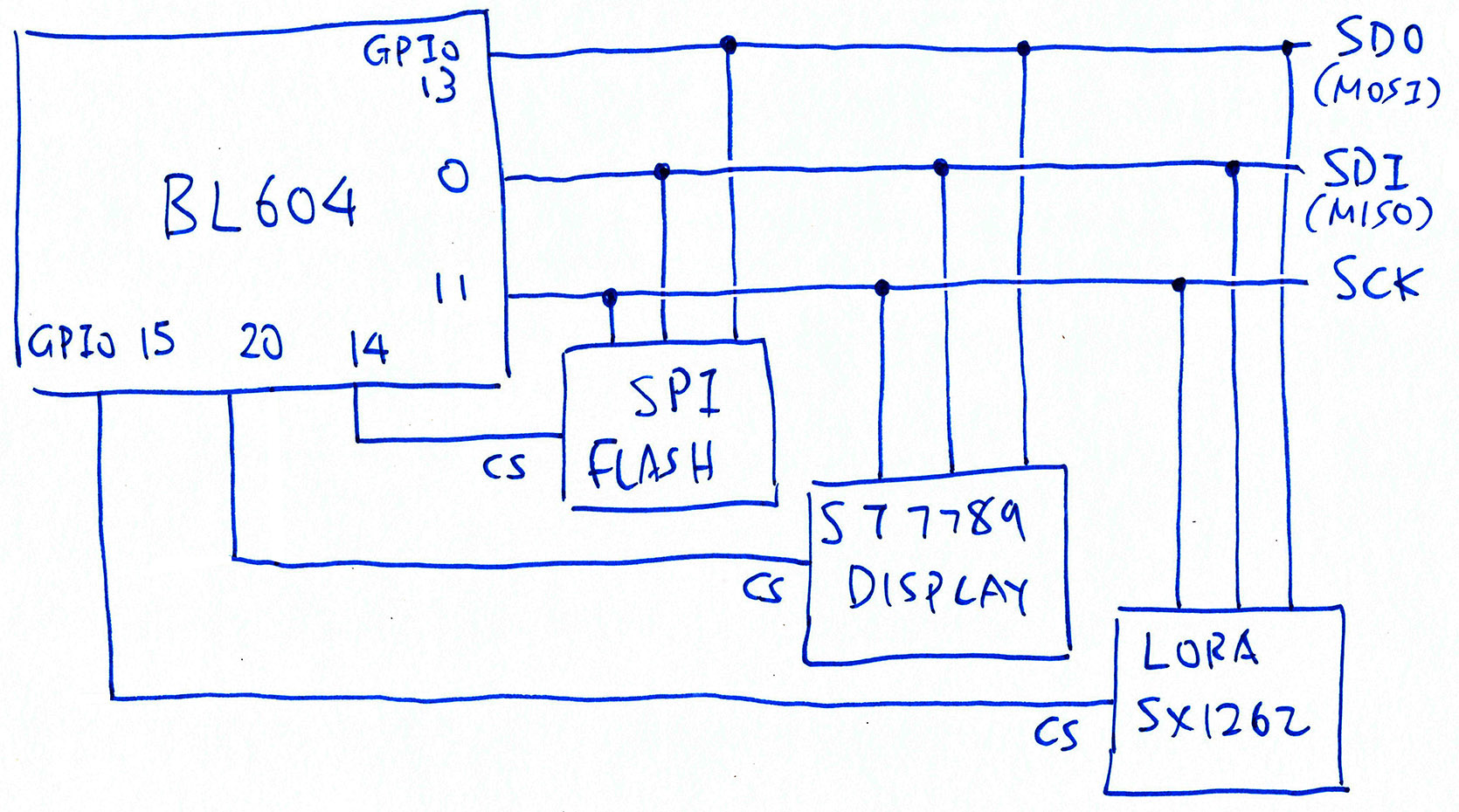
Shared SPI Bus on PineDio Stack
(Checkpoint Charlie)
PineDio Stack has a complex SPI Bus that’s shared by 3 SPI Devices (pic above)…
SPI Flash
SX1262 LoRa Transceiver
ST7789 Display
That’s why we created an SPI Device Table to manage the SPI Devices.
How do we test the SPI Bus and the SPI Device Table?
Our script sends an SPI Command to the SX1262 LoRa Transceiver to read an SX1262 Register…
nsh> spi_test2
Get Status: received
  a2 22
SX1262 Status is 2
Read Register 8: received
  a2 a2 a2 a2 80
SX1262 Register 8 is 0x80
SX1262 is OK
spi_test2 says that SX1262 Register 8 has value 0x80, which is correct.
If we receive any other value for SX1262 Register 8…
SX1262 Register 8 is 0x00
Error: SX1262 is NOT OK. Check the SPI connection
Then our script halts with an error.
Let’s look at the implementation of the checkpoint.
Our script executes the SPI Test by sending the spi_test2 command to PineDio Stack: pinedio.sh
echo "spi_test2" >/dev/ttyUSB0 ; sleep 2
And verifies that the result is correct: pinedio.sh
##  Check whether SX1262 is OK
set +e  ##  Don't exit when any command fails
match=$(grep "SX1262 Register 8 is 0x80" /tmp/test.log)
set +e  ##  Don't exit when any command fails

##  If SX1262 is not OK, quit
if [ "$match" == "" ]; then
  echo; echo "===== Error: SX1262 is NOT OK. Check the SPI connection"
  test_status=unknown
Source code for spi_test2 is located here…
Note that spi_test2 calls the SPI Test Driver “/dev/spitest0” which is explained here…
Why doesn’t it call the standard SPI Driver “/dev/spi0” instead?
That’s because the SPI Test Driver presents a simpler interface when we access the SPI Port from our NuttX App (in User Space).
At the next checkpoint, the LoRaWAN Test App will call the SPI Test Driver to talk to the SX1262 LoRa Transceiver.
(We might switch to “/dev/spitest1” to fix an SPI Race Condition)
What about testing the SPI Flash and ST7789 Display?
In future we might test the SPI Flash by reading the JEDEC ID.
Testing the ST7789 Display will be more tricky because it needs visual inspection. If you have any ideas, lemme know!
PineDio Stack talking LoRaWAN to RAKwireless WisGate LoRaWAN Gateway
(Checkpoint Delta)
Now comes the most complicated checkpoint: LoRaWAN Test.
For this test our script shall do some wireless comms…
Send a Join LoRaWAN Network Request
(To our ChirpStack LoRaWAN Gateway)
Wait for the Join Network Response from gateway
Then send a LoRaWAN Data Packet to the gateway
How will we know if LoRa and LoRaWAN are working OK on PineDio Stack?
Step 3 will succeed only if…
PineDio Stack correctly transmits the Join Network Request over LoRa and LoRaWAN
(Step 1)
And PineDio Stack correctly receives the Join Network Response over LoRa and LoRaWAN
(Step 2)
Thus our script works well for verifying that both LoRa and LoRaWAN work OK on PineDio Stack.
Which NuttX features will be tested in the LoRaWAN Test?
Plenty! We’ll test these features in the LoRaWAN Test…
GPIO Input: Read the Busy Status from SX1262 via GPIO Expander (See this)
GPIO Output: Enable Chip Select for SX1262 via GPIO Expander (See this)
GPIO Interrupt: Triggered when SX1262 transmits or receives a LoRa Packet (See this)
SPI: Transfer data and commands to SX1262 via SPI Test Driver (See this)
ADC and Internal Temperature Sensor: Seed the Strong Random Number Generator (See this)
Timers: Detect timeouts for transmit and receive (See this)
Multithreading: Background thread handles received LoRa Packets (See this)
Message Queue: Handles received LoRa Packets (See this)
Strong Random Number Generator: Generate the LoRaWAN Nonce (See this)
Alright let’s run the LoRaWAN Test already!
Our script starts the LoRaWAN Test by sending the lorawan_test command to PineDio Stack…
nsh> lorawan_test
init_entropy_pool
temperature = 25.667484 Celsius
The test begins by reading BL604’s Internal Temperature Sensor and using the temperature value to seed the Strong Random Number Generator.
Then we send the Join LoRaWAN Network Request to our LoRaWAN Gateway (ChirpStack)…
=========== MLME-Request ============
              MLME_JOIN
=====================================
STATUS      : OK
We receive the correct Join Network Response from our LoRaWAN Gateway…
=========== MLME-Confirm ============
STATUS      : OK
===========   JOINED     ============
OTAA
DevAddr     : 00F76FBF
DATA RATE   : DR_2
PineDio Stack has successfully joined the LoRaWAN Network!
We proceed to send a LoRaWAN Data Packet (“Hi NuttX”) to our LoRaWAN Gateway…
=========== MCPS-Confirm ============
STATUS      : OK
=====   UPLINK FRAME        1   =====
CLASS       : A
TX PORT     : 1
TX DATA     : UNCONFIRMED
48 69 20 4E 75 74 74 58 00
DATA RATE   : DR_3
U/L FREQ    : 923400000
TX POWER    : 0
CHANNEL MASK: 0003
Finally our script reports that the LoRaWAN Test has succeeded…
All OK! BL602 has successfully joined the LoRaWAN Network
Which means that GPIO Input / Ouput / Interrupt, SPI, ADC, Timers, Multithreading, Message Queues and Strong Random Number Generator are all working OK!
To run the LoRaWAN Test, our script sends the lorawan_test command to PineDio Stack: pinedio.sh
##  Send the LoRaWAN Test Command
echo "lorawan_test" >/dev/ttyUSB0

##  Wait 20 seconds to join the LoRaWAN Network
sleep 20
And checks whether PineDio Stack has successfully joined the LoRaWAN Network: pinedio.sh
##  Check whether BL602 has joined the LoRaWAN Network
set +e  ##  Don't exit when any command fails
match=$(grep "JOINED" /tmp/test.log)
set -e  ##  Exit when any command fails

##  If BL602 has joined the LoRaWAN Network, then everything is super hunky dory!
if [ "$match" != "" ]; then
  echo; echo "===== All OK! BL602 has successfully joined the LoRaWAN Network"
What happens if PineDio Stack fails to join the LoRaWAN Network?
PineDio Stack will retry repeatedly until it hits the timeout after 20 seconds.
Be sure that the LoRaWAN Gateway Settings are correct! The gateway will silently drop invalid requests without notifying our device.
(More about this in a while)
What’s inside lorawan_test?
lorawan_test is the LoRaWAN Test App that’s described in this article…
The app was ported from Semtech’s LoRaWAN Stack to NuttX and calls these NuttX Libraries…
LoRaWAN Library (ported from Semtech)
SX1262 Library (also ported from Semtech)
NimBLE Porting Layer (for Timers, Multithreading and Message Queues)
The Device Drivers called by the app are…
SPI Test Driver: /dev/spitest0
(Which calls the SPI Driver and SPI Device Table)
What about the ChirpStack LoRaWAN Gateway? What needs to be configured?
For the LoRaWAN Test to succeed, we must configure the Device EUI, Join EUI and App Key from the ChirpStack LoRaWAN Gateway…
Also verify that the LoRaWAN Frequency is correct…
Isn’t the LoRaWAN Test testing way too much? GPIO, SPI, ADC, Timers, Multithreading, …
Yeah someday we ought to build smaller tests for specific features like GPIO, ADC, Timers, Multithreading, … Similar to our SPI Test.
But for now we’ll have to live with the inconvenience of identifying which specific feature could have caused the LoRaWAN Test to fail.
LVGL Test App for testing the Touch Panel
(Checkpoint Echo)
For our final checkpoint we shall test…
I2C Driver “/dev/i2c0” from NuttX
CST816S Touch Panel “/dev/input0” connected to the I2C Bus
Why not test the I2C Accelerometer instead?
PineDio Stack’s Accelerometer is connected to the same I2C Bus as the Touch Panel.
But we’re not testing the Accelerometer because…
We don’t have a NuttX Driver for the Accelerometer
Touch Panel is probably more important than the Accelerometer for most devs
How do we test the Touch Panel and I2C Bus?
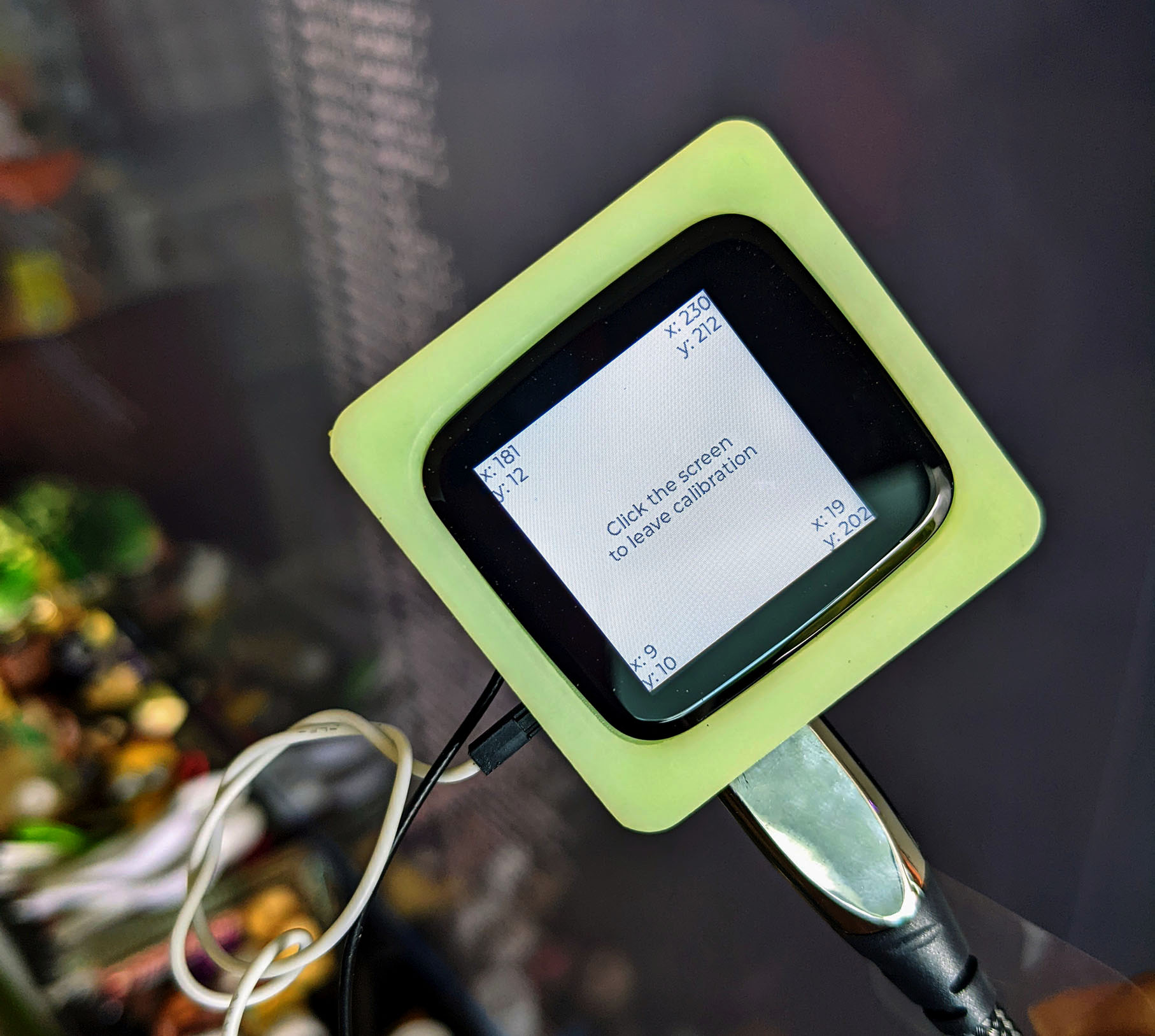
Our LVGL Test App includes a Touchscreen Calibration step that records the points touched on the Touch Panel.
We’ll run the app, tap the screen and verify that the Touch Panel generates valid Touch Data over I2C when touched.
So this isn’t automated?
Well our script starts the app automatically, but we need to run over and tap the screen when prompted. Here’s how it works…
Our script sends the lvgltest command to start the LVGL Test App…
nsh> lvgltest
tp_init: Opening /dev/input0
cst816s_open:
HELLO HUMAN: TOUCH PINEDIO STACK NOW
The script prompts us to touch the screen.
When we touch the screen, the CST816S Touch Panel Driver shows a Touch Down Event with the coordinates of the touched point (read over I2C)…
DOWN: id=0, touch=0, x=83, y=106
As we lift our finger off the screen, the driver shows a Touch Up Event…
Invalid touch data: id=9, touch=2, x=639, y=1688
UP: id=0, touch=2, x=83, y=106
(Why the Touch Data is invalid)
Our script detects the Touch Up Event and reports that the test has succeeded…
All OK! BL604 has responded to touch
Yep PineDio Stack’s Touch Panel and I2C Bus are working OK!
The Touch Panel Test lives in a separate script: pinedio2.sh
We launch the second script after completing the LoRaWAN Test: pinedio.sh
##  Start the second script: pinedio2.sh
SCRIPT_PATH="${BASH_SOURCE}"
SCRIPT_DIR="$(cd -P "$(dirname -- "${SCRIPT_PATH}")" >/dev/null 2>&1 && pwd)"
$SCRIPT_DIR/pinedio2.sh
The second script sends the lvgltest command to start the LVGL Test App: pinedio2.sh
##  Send command to PineDio Stack: lvgltest
echo "lvgltest" >/dev/ttyUSB0 ; sleep 1
echo ; echo "----- HELLO HUMAN: TOUCH PINEDIO STACK NOW" ; sleep 2

##  Wait 30 seconds for the screen to be tapped
sleep 30
And prompts us to tap the screen.
30 seconds later our script searches for a Touch Up Event: pinedio2.sh
##  Check whether BL604 has responded to touch
set +e  ##  Don't exit when any command fails
match=$(grep "cst816s_get_touch_data: UP: id=0, touch=" /tmp/test.log)
set -e  ##  Exit when any command fails

##  If BL604 has responded to touch, then everything is super hunky dory!
if [ "$match" != "" ]; then
  echo; echo "===== All OK! BL604 has responded to touch"
And reports that the test has succeeded.
What’s inside lvgltest?
lvgltest is our Test App for the LVGL Graphics Library…
When the app starts, it runs a Touchscreen Calibration…
Which we’re using to test PineDio Stack’s Touch Panel.
But the Touchreen Calibration needs us to tap the 4 corners. Our script only watches for one tap?
Yeah remember that my Spare PineDio Stack has a defective ST7789 Display. So we can’t see the 4 corners anyway.
Hopefully tapping the screen once in the centre will be sufficient for testing the Touch Panel.
(Our script should probably validate that the reported coordinates are close to the centre of the screen)
Can we fully automate the Touch Panel Test? And do away with the Manual Tapping?
Yep we need some kind of Robot Finger to tap the screen.
The finger thingy needs to apply sufficient pressure to the screen (but not too much) in order to wake up the Touch Panel. (See this)
We could use a Motorised Controller with an attached Stylus.
Or a Servo Motor wrapped with an Electrostatic Discharge Bag.
Hope it fits inside our Automated Testing Enclosure: IKEA 365+ 5.2L Food Container…
The lesson we learnt from Alice, Bob and Chow: It’s super helpful to preserve the Automated Test Logs for every NuttX Release!
(Especially when collaborating across time zones)
This how we upload the Automated Test Log to GitHub Release Notes…
##  Run the script for Auto Flash and Test for PineDio Stack BL604.
##  Capture the Test Log in /tmp/release.log
script -c remote-bl602/scripts/pinedio.sh /tmp/release.log

##  TODO: Install the GitHub CLI for uploading Release Notes: https://cli.github.com
##  Log in a GitHub Token that has "repo" and "read:org" permissions

##  Optional: Upload the Test Log to the GitHub Release Notes
remote-bl602/scripts/upload.sh
The script command runs our Automated Testing Script and captures the Automated Test Log into /tmp/release.log.
Our Upload Script upload.sh reads the Automated Test Log and uploads to GitHub Release Notes.
So the Upload Script needs write access to GitHub Release Notes?
Yes our Upload Script calls the GitHub CLI to upload the Automated Test Log to GitHub Release Notes…
We need to install the GitHub CLI and log in with a GitHub Token that has permission to update the Release Notes…
##  TODO: Create a new GitHub Token at
##  https://github.com/settings/tokens/new
##  Token must have "repo" and "read:org" permissions

##  Log in with the GitHub Token
gh auth login --with-token

##  Verify that GitHub CLI can access GitHub Releases
gh release list --repo lupyuen/nuttx
What’s inside our Upload Script?
Our Upload Script assumes that the GitHub Actions Workflow has published a GitHub Release with Auto-Generated Release Notes.
The script begins by calling the GitHub CLI to download the Auto-Generated Release Notes: upload.sh
##  Assumes the following files are present...
##  /tmp/release.log: Test Log
##  /tmp/release.tag: Release Tag (like pinedio-2022-05-10)

##  Preserve the Auto-Generated GitHub Release Notes.
##  Fetch the current GitHub Release Notes and extract the body text, like:
##  "Merge updates from master by @lupyuen in https://github.com/lupyuen/nuttx/pull/82"
gh release view \
  `cat /tmp/release.tag` \
  --json body \
  --jq '.body' \
  --repo lupyuen/nuttx \
  >/tmp/release.old
(“gh release view” is explained here)
In case the script is run twice, we search for the Previous Automated Test Log…
##  Find the position of the Previous Test Log, starting with "```"
cat /tmp/release.old \
  | grep '```' --max-count=1 --byte-offset \
  | sed 's/:.*//g' \
  >/tmp/previous-log.txt
prev=`cat /tmp/previous-log.txt`
And we remove the Previous Test Log, while retaining the Auto-Generated Release Notes…
##  If Previous Test Log exists, discard it
if [ "$prev" != '' ]; then
  cat /tmp/release.old \
    | head --bytes=$prev \
    >>/tmp/release2.log
else
  ##  Else copy the entire Release Notes
  cat /tmp/release.old \
    >>/tmp/release2.log
  echo "" >>/tmp/release2.log
fi
Just before adding the Automated Test Log, we insert the Test Status…
##  Show the Test Status, like "All OK! BL602 has successfully joined the LoRaWAN Network"
grep "^===== " /tmp/release.log \
  | colrm 1 6 \
  >>/tmp/release2.log
Then we embed the Automated Test Log, taking care of the Special Characters…
##  Enquote the Test Log without Carriage Return and Terminal Control Characters
##  https://stackoverflow.com/questions/17998978/removing-colors-from-output
echo '```text' >>/tmp/release2.log
cat /tmp/release.log \
  | tr -d '\r' \
  | sed 's/\x1B[@A-Z\\\]^_]\|\x1B\[[0-9:;<=>?]*[-!"#$%&'"'"'()*+,.\/]*[][\\@A-Z^_`a-z{|}~]//g' \
  >>/tmp/release2.log
echo '```' >>/tmp/release2.log
Finally we call the GitHub CLI to upload the Auto-Generated Release Notes appended with the Automated Test Log…
##  Upload the Test Log to the GitHub Release Notes
gh release edit \
  `cat /tmp/release.tag` \
  --notes-file /tmp/release2.log \
  --repo lupyuen/nuttx
(“gh release edit” is explained here)
That’s it for uploading the Automated Test Log to GitHub!
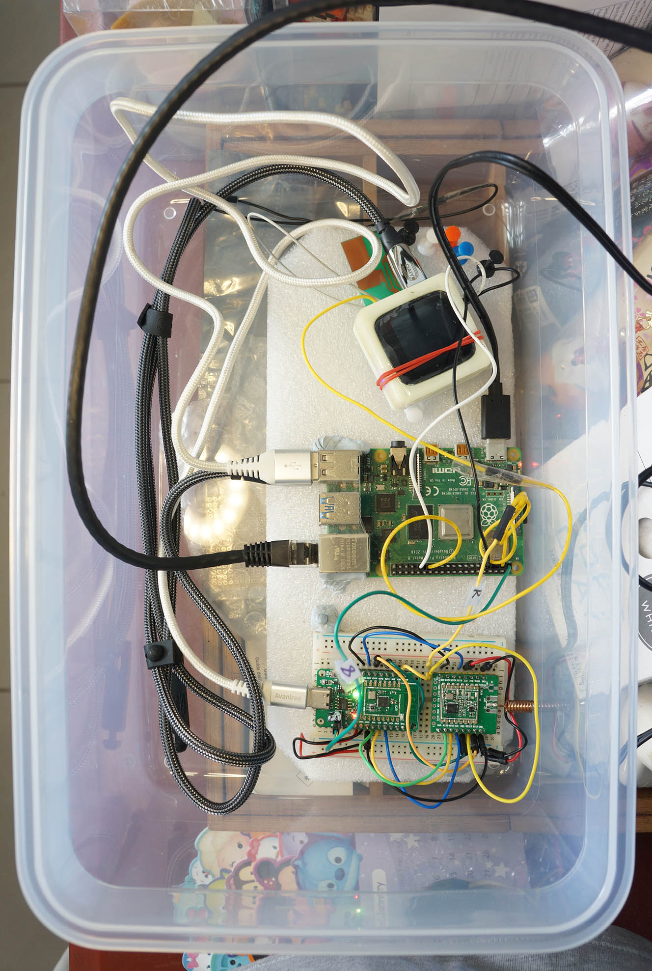
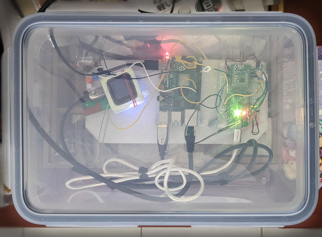
PineDio Stack BL604 (top) and PineCone BL602 (bottom) connected to Single-Board Computer for Automated Testing
Is PineDio Stack fully supported by NuttX Mainline?
Not yet. Our fork of NuttX for PineDio Stack has Experimental Features that aren’t ready to be upstreamed into NuttX Mainline…
Thus the onus is on us to pull the updates regularly from NuttX Mainline and make sure they work on PineDio Stack.
So PineDio Stack might not have the latest features from NuttX Mainline?
We’re merging updates from NuttX Mainline into the PineDio Stack repo roughly every 2 weeks. (Depends on my writing mood)
All NuttX Updates are tested on PineCone BL602 first, then merged and tested on PineDio Stack BL604. (Because PineCone is way more popular than PineDio Stack right now)
That’s why we need the complicated setup for Automated Testing with PineCone and PineDio Stack. (Pic above)
(More about the USB Ports for PineCone and PineDio Stack)
Which means we have 2 branches of NuttX: BL602 and BL604?
Yep. We’re now testing and maintaining two Stable Branches of NuttX for public consumption on BL602 and BL604…
PineCone (Release) Branch for PineCone BL602
PineDio Branch for PineDio Stack BL604
(Same for NuttX Apps)
How do we keep NuttX Mainline in sync with PineCone and PineDio Stack?
Very carefully! And with lots of Automation. (GitHub Actions and Automated Testing)
Let’s watch how the updates from NuttX Mainline get merged into PineCone and PineDio Stack…
And how updates from PineDio Stack get merged back into PineCone…
Ultimately the PineCone and PineDio Branches will have the exact same code, tested OK on PineCone and PineDio Stack. (With different build settings)
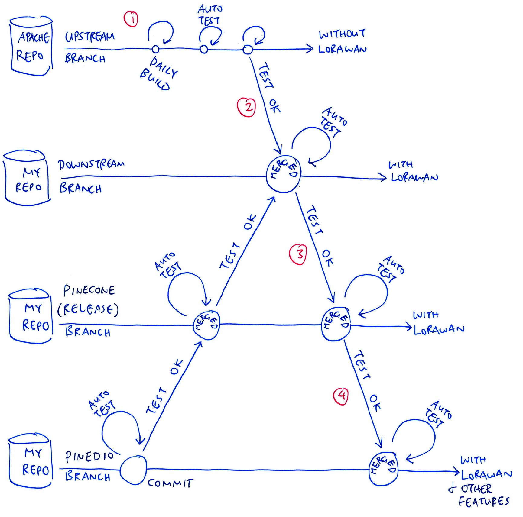
The pic above shows how we merge the updates from NuttX Mainline into the PineCone and PineDio Branches…
Every day we build Mainline NuttX (Upstream) every day with GitHub Actions. (See this)
Also daily we run our Automated Testing to verify that the Upstream Build boots OK on PineCone BL602. (Like this)
(Upstream Build doesn’t include the LoRaWAN Stack)
Every 2 weeks (roughly), we merge Upstream NuttX into our Downstream Branch. (Like this)
GitHub Actions triggers a build for the Downstream Branch. (See this)
Our Automated Testing verifies the Downstream Build with LoRaWAN on PineCone BL602. (Like this)
If the Downstream Branch has tested OK, we merge the Downstream Branch to the PineCone (Release) Branch. (Like this)
GitHub Actions triggers a build for the PineCone Branch. (See this)
Our Automated Testing verifies the PineCone (Release) Build with LoRaWAN on PineCone BL602. (Like this)
If the PineCone Branch has tested OK, we merge the PineCone (Release) Branch to the PineDio Branch. (Like this)
GitHub Actions triggers a build for the PineDio Branch. (See this)
We run our Automated Testing on PineDio Stack to verify that the PineDio Build works OK with LoRaWAN and Touch Panel. (Like this)
That’s what we do today to keep PineCone and PineDio Branches in sync with NuttX Mainline.
(We do the same for NuttX Apps, just before every merge of NuttX OS)
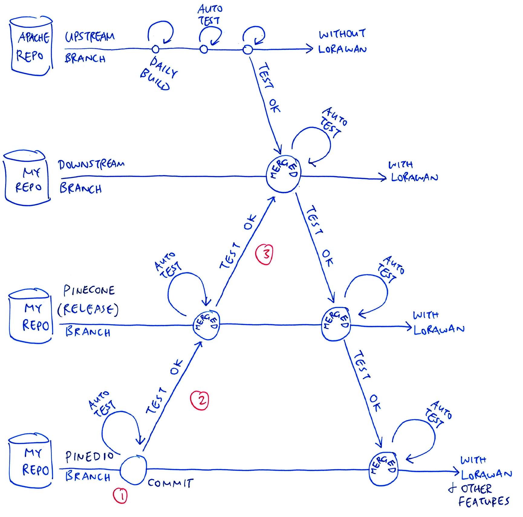
Now Reverse Uno: The pic above shows how we merge the updates from PineDio Branch back to PineCone Branch (like when we add a new feature for PineDio Stack)…
When we commit a change to the PineDio Branch, GitHub Actions triggers a build of the branch. (See this)
We run our Automated Testing on PineDio Stack to verify that the build works OK with LoRaWAN and Touch Panel. (Like this)
If the PineDio Branch has tested OK, we merge the PineDio Branch to the PineCone (Release) Branch. (Like this)
GitHub Actions triggers a build for the PineCone Branch. (See this)
Our Automated Testing verifies the PineCone (Release) Build with LoRaWAN on PineCone BL602. (Like this)
If the PineCone Branch has tested OK, we merge the PineCone (Release) Branch to the Downstream Branch. (Like this)
GitHub Actions triggers a build for the Downstream Branch. (See this)
For one last time, we run our Automated Testing on PineCone BL602 to verify that the Downstream Build works OK with LoRaWAN. (Like this)
Downstream Branch is now ready to accept new updates from NuttX Mainline. (Within the next 2 weeks)
That’s what we do today to sync the PineDio and PineCone Branches.
(We do the same for NuttX Apps, just before every merge of NuttX OS)
GPIO Expander for PineDio Stack
Hol’ up… PineCone Branch merges updates from NuttX Mainline AND PineDio Branch? Won’t they clash?
Yep maintaining the PineCone (Release) Branch is a delicate process…
We need to assure peaceful coexistence of the features from both NuttX Mainline and PineDio Stack.
Suppose NuttX Mainline implements a new feature: SPI DMA for BL602…
We need to merge the SPI DMA changes into SPI Driver for the PineCone Branch: bl602_spi.c
But recall that the SPI Driver for the PineCone Branch also includes the SPI Device Table for PineDio Stack: bl602_spi.c
Thus we need to merge the SPI DMA changes very carefully into the SPI Driver. (Possibly changing the SPI Device Table too)
To make the merging easier, we have demarcated the SPI Device Table with the PINEDIO_STACK_BL604 macro: bl602_spi.c
//  If this is PineDio Stack...
#ifdef PINEDIO_STACK_BL604
//  Code for SPI Device Table goes here...
#endif  //  PINEDIO_STACK_BL604
PINEDIO_STACK_BL604 is defined below, should probably be improved: board.h
//  Identify as PineDio Stack if both ST7789 and CST816S are present
#if defined(CONFIG_LCD_ST7789) && defined(CONFIG_INPUT_CST816S)
#define PINEDIO_STACK_BL604
#endif  //  CONFIG_LCD_ST7789 && CONFIG_INPUT_CST816S
Is there a cleaner way to merge updates from NuttX Mainline?
The cleaner way to merge updates from NuttX Mainline might be to split the NuttX Drivers for PineCone and PineDio Stack.
We did this for the NuttX GPIO Driver…
PineCone BL602 uses the BL602 EVB GPIO Driver
PineDio Stack BL604 uses the GPIO Expander Driver
We select the GPIO Driver through Kconfig and Menuconfig. Or through the NuttX Build Configuration…
## Configure build for PineCone BL602
./tools/configure.sh bl602evb:pinecone

## Configure build for PineDio Stack BL604
./tools/configure.sh bl602evb:pinedio
(See the PineDio Stack config)
(How we resolve Merge Conflicts between NuttX Mainline and our Downstream Branch)
Wow looks like we’re doing Everything Everywhere All at Once / Daily / Fortnightly for NuttX on PineDio Stack! Why are we doing all this?
PineDio Stack is the most complex IoT gadget I’ve seen… All 23 GPIOs in use, some multiplexed!
Thus we need a Common Framework to manage the complexity. And the framework shall be easily adopted by Alice, Bob, Chow and other devs worldwide to create Apps and Drivers for PineDio Stack.
The Common Framework that we have selected is Apache NuttX RTOS!
NuttX looks like Linux (shrunk to a tiny footprint), so hopefully it appeals to coders familiar with Linux.
Isn’t it difficult to coordinate our devs everywhere?
That’s why we have automated everything as much as possible, from Automated Builds (GitHub Actions) to Automated Testing.
Updates are synced from NuttX Mainline every 2 weeks, so PineDio Stack Devs will experience the same features as other NuttX Devs worldwide.
With our grand plan, no dev gets left behind across the time zones!
Are there other options?
NuttX is the only Community-Supported RTOS for BL602 and BL604.
If community support is not required, we could consider these alternatives…
(Supports WiFi and is based on FreeRTOS)
(Doesn’t support WiFi, also based on FreeRTOS)
But we might face serious challenges creating complex firmware for PineDio Stack.
I hope Alice, Bob and Chow will have a great time creating NuttX Drivers and Apps on PineDio Stack… And you too!
Lemme know what you’re building with PineDio Stack!
Many Thanks to my GitHub Sponsors for supporting my work! This article wouldn’t have been possible without your support.
Got a question, comment or suggestion? Create an Issue or submit a Pull Request here…
lupyuen.github.io/src/auto2.md
This article is the expanded version of this Twitter Thread
Automated Testing of PineCone BL602 is explained here…
The ST7789 Display on our Spare PineDio Stack for Automated Testing is faulty. How will we know if the ST7789 Driver is working?
Right now I’m manually running the LVGL Test App on my Main PineDio Stack (with a functioning display), to check if the ST7789 Driver is OK.
The test results are manually recorded in the Pull Request. (See this)
What if the Kconfig files in NuttX Mainline get updated? How do we sync the updates to the PineDio Stack Build Config?
Here’s how we sync the updates to the PineDio Stack Build Config, right after merging NuttX Mainline with PineDio Stack…
## Configure build for PineDio Stack BL604
./tools/configure.sh bl602evb:pinedio

## Copy the updated Build Config to our repo
cp .config boards/risc-v/bl602/bl602evb/configs/pinedio/defconfig

## So the next time we configure the build,
## we will use the updated Build Config...
## ./tools/configure.sh bl602evb:pinedio
PineDio Stack BL604 (top) and PineCone BL602 (bottom) connected to Single-Board Computer for Automated Testing
When we connect both PineDio Stack BL604 and PineCone BL602 to our Single-Board Computer (pic above), we’ll see two USB Devices: /dev/ttyUSB0 and /dev/ttyUSB1
How will we know which USB Device is for PineDio Stack and PineCone?
Do this…
## Show /dev/ttyUSB0
lsusb -v -s 1:3 2>&1 | grep bcdDevice | colrm 1 23

## Show /dev/ttyUSB1
lsusb -v -s 1:4 2>&1 | grep bcdDevice | colrm 1 23

## Output for Pinedio Stack BL604:
## 2.64
## See https://gist.github.com/lupyuen/dc8c482f2b31b25d329cd93dc44f0044

## Output for PineCone BL602:
## 2.63
## See https://gist.github.com/lupyuen/3ba0dc0789fd282bbfcf9dd5c3ff8908
Here’s how we override the Default USB Device for PineDio Stack…
##  Tell the script to use /dev/ttyUSB1
##  (Default is /dev/ttyUSB0)
export USB_DEVICE=/dev/ttyUSB1

##  Auto flash and test PineDio Stack BL604 at /dev/ttyUSB1
remote-bl602/scripts/pinedio.sh
TODO: We should automate this selection of USB Device in our Automated Testing Script.